EP0144171A1 - Montage d'aimants - Google Patents
Montage d'aimants Download PDFInfo
- Publication number
- EP0144171A1 EP0144171A1 EP84307735A EP84307735A EP0144171A1 EP 0144171 A1 EP0144171 A1 EP 0144171A1 EP 84307735 A EP84307735 A EP 84307735A EP 84307735 A EP84307735 A EP 84307735A EP 0144171 A1 EP0144171 A1 EP 0144171A1
- Authority
- EP
- European Patent Office
- Prior art keywords
- coils
- assembly
- superconducting coil
- magnetic field
- magnet
- Prior art date
- Legal status (The legal status is an assumption and is not a legal conclusion. Google has not performed a legal analysis and makes no representation as to the accuracy of the status listed.)
- Granted
Links
- XEEYBQQBJWHFJM-UHFFFAOYSA-N Iron Chemical compound [Fe] XEEYBQQBJWHFJM-UHFFFAOYSA-N 0.000 claims description 28
- 238000000429 assembly Methods 0.000 claims description 27
- 230000000712 assembly Effects 0.000 claims description 27
- 229910052742 iron Inorganic materials 0.000 claims description 14
- 238000003384 imaging method Methods 0.000 claims description 11
- 239000000696 magnetic material Substances 0.000 claims description 2
- 230000003213 activating effect Effects 0.000 claims 1
- 230000001419 dependent effect Effects 0.000 claims 1
- 238000005481 NMR spectroscopy Methods 0.000 description 18
- 239000001307 helium Substances 0.000 description 17
- 229910052734 helium Inorganic materials 0.000 description 17
- SWQJXJOGLNCZEY-UHFFFAOYSA-N helium atom Chemical compound [He] SWQJXJOGLNCZEY-UHFFFAOYSA-N 0.000 description 17
- 239000007788 liquid Substances 0.000 description 7
- 238000004804 winding Methods 0.000 description 7
- IJGRMHOSHXDMSA-UHFFFAOYSA-N Atomic nitrogen Chemical compound N#N IJGRMHOSHXDMSA-UHFFFAOYSA-N 0.000 description 6
- 239000004411 aluminium Substances 0.000 description 5
- XAGFODPZIPBFFR-UHFFFAOYSA-N aluminium Chemical compound [Al] XAGFODPZIPBFFR-UHFFFAOYSA-N 0.000 description 5
- 229910052782 aluminium Inorganic materials 0.000 description 5
- 238000001816 cooling Methods 0.000 description 4
- 238000000034 method Methods 0.000 description 4
- 239000004020 conductor Substances 0.000 description 3
- 238000010586 diagram Methods 0.000 description 3
- 229910052757 nitrogen Inorganic materials 0.000 description 3
- 230000005855 radiation Effects 0.000 description 3
- 239000002887 superconductor Substances 0.000 description 3
- 238000009835 boiling Methods 0.000 description 2
- 230000000694 effects Effects 0.000 description 2
- 238000002474 experimental method Methods 0.000 description 2
- 239000007789 gas Substances 0.000 description 2
- 239000000203 mixture Substances 0.000 description 2
- 239000010935 stainless steel Substances 0.000 description 2
- 229910001220 stainless steel Inorganic materials 0.000 description 2
- 239000004593 Epoxy Substances 0.000 description 1
- 239000000956 alloy Substances 0.000 description 1
- 229910045601 alloy Inorganic materials 0.000 description 1
- 238000003491 array Methods 0.000 description 1
- 230000015556 catabolic process Effects 0.000 description 1
- 239000002131 composite material Substances 0.000 description 1
- 238000010276 construction Methods 0.000 description 1
- 238000013461 design Methods 0.000 description 1
- 238000010292 electrical insulation Methods 0.000 description 1
- 239000000284 extract Substances 0.000 description 1
- 239000011521 glass Substances 0.000 description 1
- 239000003365 glass fiber Substances 0.000 description 1
- 231100001261 hazardous Toxicity 0.000 description 1
- 238000009434 installation Methods 0.000 description 1
- 239000011159 matrix material Substances 0.000 description 1
- 238000005259 measurement Methods 0.000 description 1
- 238000012986 modification Methods 0.000 description 1
- 230000004048 modification Effects 0.000 description 1
- 230000002085 persistent effect Effects 0.000 description 1
- 238000012545 processing Methods 0.000 description 1
- 238000010791 quenching Methods 0.000 description 1
- 230000000171 quenching effect Effects 0.000 description 1
Images



Classifications
-
- G—PHYSICS
- G01—MEASURING; TESTING
- G01R—MEASURING ELECTRIC VARIABLES; MEASURING MAGNETIC VARIABLES
- G01R33/00—Arrangements or instruments for measuring magnetic variables
- G01R33/20—Arrangements or instruments for measuring magnetic variables involving magnetic resonance
- G01R33/28—Details of apparatus provided for in groups G01R33/44 - G01R33/64
- G01R33/42—Screening
- G01R33/421—Screening of main or gradient magnetic field
-
- G—PHYSICS
- G01—MEASURING; TESTING
- G01R—MEASURING ELECTRIC VARIABLES; MEASURING MAGNETIC VARIABLES
- G01R33/00—Arrangements or instruments for measuring magnetic variables
- G01R33/20—Arrangements or instruments for measuring magnetic variables involving magnetic resonance
- G01R33/28—Details of apparatus provided for in groups G01R33/44 - G01R33/64
- G01R33/38—Systems for generation, homogenisation or stabilisation of the main or gradient magnetic field
- G01R33/381—Systems for generation, homogenisation or stabilisation of the main or gradient magnetic field using electromagnets
- G01R33/3815—Systems for generation, homogenisation or stabilisation of the main or gradient magnetic field using electromagnets with superconducting coils, e.g. power supply therefor
-
- G—PHYSICS
- G01—MEASURING; TESTING
- G01R—MEASURING ELECTRIC VARIABLES; MEASURING MAGNETIC VARIABLES
- G01R33/00—Arrangements or instruments for measuring magnetic variables
- G01R33/20—Arrangements or instruments for measuring magnetic variables involving magnetic resonance
- G01R33/28—Details of apparatus provided for in groups G01R33/44 - G01R33/64
- G01R33/38—Systems for generation, homogenisation or stabilisation of the main or gradient magnetic field
- G01R33/387—Compensation of inhomogeneities
- G01R33/3875—Compensation of inhomogeneities using correction coil assemblies, e.g. active shimming
-
- Y—GENERAL TAGGING OF NEW TECHNOLOGICAL DEVELOPMENTS; GENERAL TAGGING OF CROSS-SECTIONAL TECHNOLOGIES SPANNING OVER SEVERAL SECTIONS OF THE IPC; TECHNICAL SUBJECTS COVERED BY FORMER USPC CROSS-REFERENCE ART COLLECTIONS [XRACs] AND DIGESTS
- Y10—TECHNICAL SUBJECTS COVERED BY FORMER USPC
- Y10S—TECHNICAL SUBJECTS COVERED BY FORMER USPC CROSS-REFERENCE ART COLLECTIONS [XRACs] AND DIGESTS
- Y10S505/00—Superconductor technology: apparatus, material, process
- Y10S505/825—Apparatus per se, device per se, or process of making or operating same
- Y10S505/879—Magnet or electromagnet
Definitions
- the invention relates to a magnet assembly and particularly to a magnet assembly suitable for use in nuclear magnetic resonance (NMR) imaging.
- NMR nuclear magnetic resonance
- NMR nuclear magnetic resonance
- Iron shielding is cumbersome and expensive. For example, in order to prevent the external magnetic field exceeding 5.0 Gauss beyond a radius of 5 metres requires 3 tonnes of iron for a magnet assembly generating a 1.5 kG bore field, while up to 40 tonnes of iron is required to shield a magnet assembly generating a 20 kG bore field. Clearly, the engineering required to support such large amounts of iron is expensive and furthermore the nearer the iron is to the magnet assembly, the more the bore field itself can be distorted. This is particularly undesirable in the case of magnet assemblies used for NMR imaging where a closely controlled uniform bore field is essential.
- US-A-3333162 also discloses a small scale shielding arrangement. This arrangement provides no further assistance to someone trying to solve the problems outlined above for a number of reasons. Firstly, this arrangement of coils could never be used for NMR work because of rotation of the principal field vector in the bore, therefore the device as described could not be copied or scaled up directly. Secondly the device is dealing with magnetic fields very much less than those necessary for NMR. We estimate that the bore field of the largest coil in the Hz component would be about 460 Gauss while at distances of between 20 and 30 cms the fringe field would in any case be less than the earths field. We require a magnet assembly where preferably the fringe field very close to the surface of the assembly is reduced to something of the order of magnitude of the earths field and a device which is open at the ends for patient access.
- a magnet assembly comprising a first superconducting coil assembly for generating a first magnetic field; and a second superconducting coil assembly for generating a second magnetic field, the second superconducting coil assembly being electrically connected in series with the first superconducting coil assembly, wherein the first and second superconducting coil assemblies each generate, in use, magnetic fields whose corresponding components are of substantially the same order of magnitude, the assemblies being arranged such that a resultant, uniform magnetic field is generated in a working volume, and the second magnetic field opposes the first magnetic field externally of the magnet assembly.
- This invention provides a self-contained magnet assembly which does not require additional external shielding devices and in addition can generate a useful (ie. high strength), uniform magnetic field in the working volume.
- a useful (ie. high strength), uniform magnetic field in the working volume As explained above, in the past, although shielding using coils has been proposed, these coils have produced small external magnetic fields whereas with the invention the second superconducting coil assembly not only provides a shielding field but also contributes significantly to the resultant magnetic field in the working volume.
- the uniformity arises by virtue of balancing to zero the higher order field terms of both coil assemblies. In principle, it is possible to balance the first and second coil assemblies separately so that each provides a uniform field and when these two are superpositioned the result is also uniform. The resultant magnetic field in the working volume is thus due to the difference in zero order terms between the fields generated by the two coil assemblies. This leads to a considerable increase in control of the uniformity of the bore magnetic field.
- a further important advantage of the invention is that the two superconducting coil assemblies are electrically connected in series. This means that when the strength of the bore magnetic field is changed by changing the current flowing through the first superconducting coil assembly the second magnetic field will automatically change by an amount sufficient so that the same degree of shielding is achieved. In other words, the shielding system is linear.
- Superconducting coil assemblies are used in order to achieve the strength and the high degree of precision of magnetic field which is required for NMR imaging.
- the superconductive condition of the coils is achieved by cooling the coils to very low temperatures of the order of 4.2 K using conventional cryogenic or refridgeration techniques.
- the coils are preferably operated in persistent mode in or to avoid field noise.
- the self-shielded or self-contained magnet assembly is particularly advantageous in enabling substantial site arrangement and installation costs to be avoided. Furthermore, the shield constituted by the second superconducting coil assembly can be designed and constructed with great accuracy and will not reduce the uniformity of the magnetic field in the working volume. Indeed, the shield field contributes to the control of magnetic field in the working volume. In addition, more shielding is possible than would be practicable with the conventional iron containment methods.
- the direction of electrical current through the second superconducting coil assembly will be opposite to the current direction in the first superconducting coil assembly.
- the first and second coil assemblies each comprise a single coil, the two coils being electrically connected in series.
- one or both of the first and second coil assemblies comprises a plurality of coaxial coils arranged symmetrically about a mid-plane of the magnet assembly normal to the coil axis.
- both the first and second assemblies comprise pluralities of coils
- the two axes and the two mid-planes will be coincident. This makes it particularly straight forward to obtain uniformity of the resultant magnetic field in the working volume (ie. the bore of the assembly).
- the coils of the second superconducting coil assembly will have a larger internal radius than the external radius of the coils of the first superconducting coil assembly.
- a special feature of using concentric coils is that it is possible to balance orders between the first coil assembly (magnet) and the second coil assembly (shield) so that, if considered independently, the magnet and the shield would not provide uniform fields and the uniformity is only achieved when the two are operated together.
- the first and second superconducting coil assemblies each comprise six superconducting coils, the coils constituting the first superconducting coil assembly being arranged radially inwardly of the coils constituting the second superconducting coil assembly, and all the coils being arranged coaxially and symmetrically about a common mid-plane normal to the coil axis.
- the degree of shielding particularly in the axial direction achieved by the magnet assembly described will normally be sufficient for normal practical purposes. In some cases, however, it may be convenient additionally to provide a further shield of magnetic material arranged around at least the first superconducting coil assembly. In particular this will reduce further the radial fringe field.
- this further shield could be positioned around the second superconducting coil assembly or preferably between the first and second coil assemblies.
- the further shield is provided adjacent to the coil or coils of the second superconducting coil assembly. This may most conveniently be achieved by constructing a former supporting the second superconducting coil assembly as the further shield.
- the further shield is made of iron. This can enable the amount of expensive superconductor in the second coil assembly to be reduced. We believe that a significant reduction can be achieved by using only 6000 kgof iron for a 1.5 T bore field.
- Further shielding may be achieved, if necessary, by providing additional coil assemblies positioned adjacent to each end of the working volume, the further coil assemblies being arranged to oppose the resultant magnetic field generated by the first and second superconducting coil assemblies at these positions.
- These further coil assemblies will normally be resistive coils since the field required is relatively small. This also allows the diameters of the coils to be made large without requiring a large cryostat.
- the further coils could, however, be superconducting and in this case they could be electrically connected in series with the first and second superconducting coil assemblies.
- Figure 1 illustrates in exploded and partly cut away form a magnet assembly 1.
- the magnet assembly 1 comprises an inner, cylindrical former 2 made of a glass fibre epoxy composite defining the working volume of the magnet assembly constituted by a bore 3 having an axis 4. Positioned radially outwardly of the former 2 is a cylindrical, aluminium former 5 coaxial with the axis 4.
- the former 5 carries three pairs of coils A,A' -C,C' arranged symmetrically about a mid-plane 6 of the assembly normal to the axis 4 ( Figure 2).
- Each of the coils A-C is formed from a superconductive conducting material which typically comprises fine strands of alloy Type II superconductor, a matrix of good normal conductor in which the superconductor strands are embedded in the form of a regular array, and a surface electrical insulation to cope with energisation and fault mode voltages. The position and number of turns of each coil will be described later.
- Each of the pairs of coils A,A' -C,C' is wound separately, one being positioned radially inwardly of the other. The coils are embedded in a wax composition and then surrounded by a clamping ring (not shown). In addition each pair of coils is positioned between respective pairs of annular ribs 5A, 5B etc of the former 5.
- the purpose of the wax composition and the ribs is to prevent significant movement of the windings of the coil in use since any small movement will be accompanied by the generation of a small amount of heat leading to breakdown of the superconductive condition (known as quenching).
- quenching a small amount of heat leading to breakdown of the superconductive condition
- the former 5 In view of the close spacing of the coils A-C, the former 5 must be constructed to accommodate large forces between adjacent coils which, in the axial direction, can amount to some 200,000 Kg. In addition, the former 5 must be as light as possible to reduce the overall weight of the magnet assembly and be as near to a right cylinder as possible.
- a second, aluminium former 7 is mounted radially outwardly of the former 5.
- the former 7 carries 6 shielding coils D-F ( Figure 2) arranged symmetrically about the mid-plane 6 of the magnet assembly in a manner to be described below.
- the coils D-F are mounted between respective pairs of ribs 7F 7E of the former 7 in a way similar to the coils A,A' -C,C'.
- Clamping rings (not shown) and wax are also used to reduce movement of the coil windings. The clamping rings are particularly important because counter-running currents in the two sets of coils cause very large radial forces to develop.
- a helium can defined by an outer cylindrical wall 8 and an inner wall having a central cylindrical portion 9 and a pair of radially outer, cylindrical portions 10 (only one of which is visible in Figure 1).
- the portions 9, 10 are integrally connected by annular web portions 11.
- the helium can is closed by a pair of ring members 12.
- the wall 8, portions 9, 10, 11 and ring members 12 are all made of stainless steel. Liquid helium is supplied to the helium can via an inlet 13 mounted in a turret 14.
- Cylindrical, aluminium radiation shields 15, 15' are mounted coaxially, radially outwardly and inwardly respectively about the helium can to define an evacuated space 16 between the shields 15,15' and the helium can.
- the shields 15,15' are cooled by contact with helium through the agency of a heat exchanger (not shown) in the turret 14 which extracts heat from the radiation shields 15, 15' and passes it to the cold helium gas that has been boiled from the helium can.
- the various shields are supported by a system of glass rods (not shown) mounted in corresponding attachment plates. These rods when configured as a three dimensional array of struts will support a 4000 kilogram magnet at the expense of a heat leak of no more than 0.04 watts.
- the helium can is filled with liquid helium which will be at 4.2 K.
- liquid helium which will be at 4.2 K.
- the gas produced will pass into the heat exchanger in the turret 14 which will cool the shields 15,15' to a temperature of about 40°K.
- the boiling of the liquid helium maintains the wall of the helium can at 42°K.
- Liquid nitrogen being present in the cooling tubes (not shown) maintains the shields 17,17' at a temperature of about 77 K. This jacket of liquid nitrogen together with the vacuum contained within the spaces 16, 18, 21 help to maintain the temperature of the helium can at 4.2 K.
- the spaces 16, 18 21 are connected through valves (not shown) within the turret 14 to the atmosphere to enable the spaces to be evacuated.
- the arrangement of the coils A-F may best be understood by considering the field at the centre of a set of circular, coplanar coils arranged on the surface of a cylinder. This field is proportional to the radius for each ampere of current through the coils. If the bore field is B and the field of a point outside the magnet assembly is B f" then for the magnet (M) constituted by the inner coils A,A' -C,C' and the antimagnet (A) constituted by the coils D-F we have:-
- each coil A-F can be characterised by four measurements. These are indicated in Figure 2. These comprise the inner radius a 1 , the outer radius a2, the distance parallel to the axis 4 of the nearest part of the coil from the mid-plane 6 (b l ) and the furthest distance from the mid-plane 6 (b 2 ). It will be appreciated from Figure 2 that the coils A-F all have a rectangular cross-section.
- Table 1 below illustrates how for coils of different diameter the bore field and fringe field changes.
- the coil is assumed to have 1,432,664 amp turns with a radius of a cms.
- the bore field is B 0 while the fringe field at a radius of 400 cms in the mid-plane of the coil is designated B r while the fringe field at a distance of 400 cms from the centre of the coil along the axis of the coil is designated B z .
- the fringe fields are represented by their z components ie. the components parallel with the axis of the coils.
- An inner coil is now chosen, for example a coil with a radius of .60 cms, and an outer coil is then selected which is as close as possible radially to the inner coil but which has a slightly reduced strength so that the fringe fields match.
- the main magnet is taken to have a radius of 60 cms it will produce a bore field of 15000 Gauss and a mean fringe field of 40.1 Gauss (see Table 1).
- a shield coil having a radius of 80 cms will by itself produce a bore field of 11250 Gauss and a mean fringe field of 73.1 Gauss. The shield coil will be run in the opposite sense to the main coil.
- the shield coil In order to balance the fringe fields so that they cancel it is necessary to reduce the number of amp turns in the shield coil by 40.1/73.1 ie. to 786,560 amp turns.
- the shield coil will thus then produce a bore field of 6176 Gauss and a mean fringe field of 40.1 Gauss.
- This particular arrangement can produce a 2.0T bore field having a very high homogeneity and a field stability of ⁇ 0.1 ppm per hour.
- a field of 2.0 T is obtained using a current of 429 Amperes.
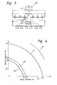
- a power supply 26 is connected via a switch 27 and a protection resistor 28 of 0.5 ohms in parallel with the coils D-F.
- Each set of coils D-F is connected in series with the coils A, A'- C, C'.
- Additional 0.5 ohm protection resistors 29, 30 are positioned in parallel with all the coils A, A' - C, C' and the coils B, B' - C, C' respectively.
- FIG. 4 The effectiveness of the outer set of coils D-F on shielding the magnet assembly can be seen from Figure 4.
- an unshielded magnet producing a bore field of 15 kG
- an external field having a strength of 10G will be experienced at a distance of 10 metres from the mid-plane 6 of the magnet assembly and up to 7.5 metres from the axis 4 of the magnet assembly as is illustrated by a line 31 in Figure 4.
- a dashed line 32 indicates the position where the external field strength has dropped to 5G.
- lines 33, 34 illustrate the positions where the external field strength has dropped to 10G and 5G respectively with the magnet assembly shown in Figures 1 and 2.
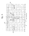
- Figure 5 illustrates an alternative coil geometry in which the inner coils A, A' - C, C' have been replaced by two pairs of coils 35, 36.
- Each coil 35 has 4098 turns and each coil 36 has 2000 turns.
- the coils D-F have been replaced by a single solenoid 37 having 4400 turns positioned 100 cms from the axis 4 and extending to 64 cms on either side of the mid-plane 6.
- the assembly shown in the previous figures is sufficiently shielded but in some cases it may be desirable to provide some extra shielding.
- One way in which this may be achieved is illustrated in Figures 6A and 6B.
- the magnet assembly 1 which is the same as that shown in Figure 1, is surrounded by four rectangular iron plates 38 positioned parallel with the axis 4.
- a pair of resistive coils 39 are positioned transversely to the axis 4 at positions spaced from the ends of the bore 3.
- each coil 39 will have a diameter of three metres, have 50 turns and be powered from separate power supplies (not shown) by a current of between 100 and 150 A.
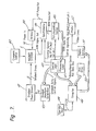
- Figure 7 illustrates in block diagram form such apparatus which is otherwise of a conventional form.
- the apparatus comprises the magnet system 1 incorporating a power supply (not shown).
- the inlets to the helium can and the space 18 are connected to suitable supplies whose operation is controlled by a cryogenic control system 40 of a conventional type.
- the former 2 carries a number of gradient coils so that different gradients of magnetic field can be set up through the bore 3 to enable NMR imaging experiments to be carried out.
- These gradient coils are not superconducting coils and are also of a conventional form. They are driven by respective power drivers 41 controlled from control logic 42 via a waveform generator 43. Coils (not shown) for generating and receiving RF energy are also mounted on the former 2, the RF transmitter being connected to an amplifier 44 which is connected to a spectrometer 45. The RF receiver which detects the NMR signal is also connected to the spectrometer 45. The generation of RF pulses is controlled by the control logic 42 which is connected to the spectrometer 45. NMR data from the spectrometer 45 passes to a data acquisition system 46 which is controlled by the control logic 42. Data from the system 46 then passes to processing logic logic 47.
- the overall control of the system is provided by a computer 48 which is connected via a conventional RS 232 interface to an operator input station 49.
- Information for the computer is stored in a disc drive 50 while the results of the imaging experiments are passed by the computer to a display system 51 which can display "slices" through the patient's body on a monitor 52.
- a patient lies inside the bore 3 extending along the axis 4 of the assembly which is conventionally termed the Z direction.
- Table 3 illustrates typical dimensions of a conventional unshielded magnet assembly and the magnet assembly shown in Figure 1 for comparison. The figures relate to a 1.5 T bore field with a 1 metre diameter bore.
Landscapes
- Physics & Mathematics (AREA)
- Condensed Matter Physics & Semiconductors (AREA)
- General Physics & Mathematics (AREA)
- Health & Medical Sciences (AREA)
- Epidemiology (AREA)
- Electromagnetism (AREA)
- Magnetic Resonance Imaging Apparatus (AREA)
Priority Applications (1)
| Application Number | Priority Date | Filing Date | Title |
|---|---|---|---|
| AT84307735T ATE50082T1 (de) | 1983-11-11 | 1984-11-09 | Magnetanordnung. |
Applications Claiming Priority (4)
| Application Number | Priority Date | Filing Date | Title |
|---|---|---|---|
| GB838330198A GB8330198D0 (en) | 1983-11-11 | 1983-11-11 | Magnet assembly |
| GB8330198 | 1983-11-11 | ||
| GB848400684A GB8400684D0 (en) | 1984-01-11 | 1984-01-11 | Shielded magnet system |
| GB8400684 | 1984-01-11 |
Related Child Applications (2)
| Application Number | Title | Priority Date | Filing Date |
|---|---|---|---|
| EP87111469A Division EP0251342A3 (fr) | 1983-11-11 | 1984-11-09 | Montage d'aimants |
| EP87111469.0 Division-Into | 1987-08-07 |
Publications (2)
| Publication Number | Publication Date |
|---|---|
| EP0144171A1 true EP0144171A1 (fr) | 1985-06-12 |
| EP0144171B1 EP0144171B1 (fr) | 1990-01-31 |
Family
ID=26286998
Family Applications (2)
| Application Number | Title | Priority Date | Filing Date |
|---|---|---|---|
| EP87111469A Withdrawn EP0251342A3 (fr) | 1983-11-11 | 1984-11-09 | Montage d'aimants |
| EP84307735A Expired EP0144171B1 (fr) | 1983-11-11 | 1984-11-09 | Montage d'aimants |
Family Applications Before (1)
| Application Number | Title | Priority Date | Filing Date |
|---|---|---|---|
| EP87111469A Withdrawn EP0251342A3 (fr) | 1983-11-11 | 1984-11-09 | Montage d'aimants |
Country Status (4)
| Country | Link |
|---|---|
| US (1) | US4587504A (fr) |
| EP (2) | EP0251342A3 (fr) |
| JP (1) | JPH0564634A (fr) |
| DE (1) | DE3481247D1 (fr) |
Cited By (29)
| Publication number | Priority date | Publication date | Assignee | Title |
|---|---|---|---|---|
| GB2158248A (en) * | 1984-04-26 | 1985-11-06 | Yokogawa Hokushin Electric | Magnetic coil assembly for nuclear magnetic resonance imaging apparatus |
| EP0167243A3 (en) * | 1984-07-06 | 1987-05-27 | The Board Of Trustees Of The Leland Stanford Junior University | Magnetic structure |
| EP0238909A1 (fr) * | 1986-03-19 | 1987-09-30 | Siemens Aktiengesellschaft | Aimant de champ principal dans un arrangement pour la production d'images par la technique à résonance magnétique nucléaire |
| EP0231879A3 (fr) * | 1986-02-06 | 1987-10-21 | General Electric Company | Bobines blindées de gradient pour la formation d'images de résonance magnétique nucléaire |
| EP0160350B1 (fr) * | 1984-04-30 | 1989-03-29 | Oxford Magnet Technology Limited | Assemblage magnétique |
| GB2209223A (en) * | 1987-08-29 | 1989-05-04 | Fuji Electric Co Ltd | Coil assembly for generating a homogeneous magnetic field |
| GB2162641B (en) * | 1984-07-11 | 1989-05-17 | Magnex Scient Limited | Nuclear magnetic resonance |
| EP0317853A1 (fr) * | 1987-11-24 | 1989-05-31 | Siemens Aktiengesellschaft | Montage d'aimants pour un appareil de tomographie à spin nucléaire à bobines supraconductrices de champ principal et bobines de gradient normalement conductrices |
| GB2215471A (en) * | 1988-02-03 | 1989-09-20 | Fuji Electric Co Ltd | Superconducting magnet |
| US4876510A (en) * | 1987-06-04 | 1989-10-24 | Siemens Aktiengesellschaft | Apparatus for nuclear spin tomography having superconducting base field magnetic coils and a radiation shield |
| EP0350262A1 (fr) * | 1988-07-05 | 1990-01-10 | General Electric Company | Support d'un écran de radiation dans un aimant à résonance magnétique |
| DE3924579A1 (de) * | 1988-07-27 | 1990-02-01 | Mitsubishi Electric Corp | Supraleitende magnetanordnung |
| GB2221540A (en) * | 1985-09-20 | 1990-02-07 | Nat Res Dev | Magnetic field screens |
| EP0310212A3 (fr) * | 1987-09-28 | 1990-04-25 | Ga Technologies Inc. | Système de production d'images par résonance magnétique et son procédé de fabrication |
| DE3891385T1 (de) * | 1988-09-08 | 1990-08-30 | Mitsubishi Electric Corp | Supraleitende magnetvorrichtung |
| WO1990013824A1 (fr) * | 1989-04-29 | 1990-11-15 | Bruker Analytische Messtechnik Gmbh | Systeme magnetique a bobines inductrices supraconductrices |
| GB2232771A (en) * | 1989-04-23 | 1990-12-19 | Elscint Ltd | Actively and passively shielded MR magnet |
| GB2247355A (en) * | 1990-08-24 | 1992-02-26 | Mitsubishi Electric Corp | Superconducting magnet apparatus |
| US5210512A (en) * | 1990-07-24 | 1993-05-11 | Oxford Magnet Technology Ltd. | Magnet assembly |
| US5329266A (en) * | 1990-07-24 | 1994-07-12 | Oxford Magnet Technology Ltd. | Magnet assembly |
| DE4344287C1 (de) * | 1993-12-23 | 1995-06-14 | Siemens Ag | Supraleitender Magnet mit aktiver Schirmung für Kernspintomographieanlagen |
| EP0727672A1 (fr) * | 1995-02-14 | 1996-08-21 | Kabushiki Kaisha Toshiba | Aimant générant le champ magnétique statique d'un système d'IRM comprenant un écran magnétique actif |
| EP0317775B1 (fr) * | 1987-11-25 | 1996-08-28 | General Electric Company | Bobines de gradients équilibrées et auto-blindées |
| US6265960B1 (en) | 1999-08-27 | 2001-07-24 | Bruker Ag | Actively shielded magnet system with Z2 shim |
| WO2003023433A1 (fr) * | 2001-09-06 | 2003-03-20 | Oxford Instruments Superconductivity Limited | Dispositif s'utilisant dans un systeme d'irm |
| WO2004029644A1 (fr) * | 2002-09-30 | 2004-04-08 | Oxford Instruments Plc | Assemblage d'aimant |
| WO2004029645A1 (fr) * | 2002-09-30 | 2004-04-08 | Oxford Instruments Plc | Ensemble de production de champ magnetique et procede associe |
| US7330341B2 (en) | 2005-10-06 | 2008-02-12 | Bruker Biospin Gmbh | Superconducting magnet coil system with quench protection |
| DE102009004899A1 (de) | 2009-01-16 | 2010-09-16 | Siemens Aktiengesellschaft | Supraleitender aktiv geschirmter Magnet |
Families Citing this family (46)
| Publication number | Priority date | Publication date | Assignee | Title |
|---|---|---|---|---|
| US4853588A (en) * | 1986-09-05 | 1989-08-01 | Denki Onkyo Co., Ltd. | Deflection yoke apparatus with means for reducing unwanted radiation |
| US4924186A (en) * | 1986-09-29 | 1990-05-08 | Kabushiki Kaisha Toshiba | Magnetic resonance imaging system with auxiliary compensation coil |
| FR2606624A1 (fr) * | 1986-11-14 | 1988-05-20 | Thomson Cgr | Installation d'imagerie par resonance magnetique nucleaire |
| GB8701363D0 (en) * | 1987-01-22 | 1987-02-25 | Oxford Instr Ltd | Magnetic field generating assembly |
| USD306577S (en) | 1987-03-27 | 1990-03-13 | Kabushiki Kaisha Toshiba | Superconducting magnet for magnetic resonance imaging apparatuses |
| US4771256A (en) * | 1987-04-02 | 1988-09-13 | General Electric Company | Integral shield for mr magnet |
| US4837541A (en) * | 1987-04-02 | 1989-06-06 | General Electric Company | Shield suspension system for a magnetic resonance cryostat |
| US4800354A (en) * | 1987-04-02 | 1989-01-24 | General Electric Company | Superconducting magnetic resonance magnet and method of making same |
| JPS63284805A (ja) * | 1987-05-18 | 1988-11-22 | Mitsubishi Electric Corp | 超電導電磁石装置 |
| IL82950A (en) * | 1987-06-22 | 1990-12-23 | Elscint Ltd | Superconducting magnet with separate support system |
| JPS64715A (en) * | 1987-06-23 | 1989-01-05 | Mitsubishi Electric Corp | Superconducting electromagnet device |
| US4768008A (en) * | 1987-07-31 | 1988-08-30 | General Atomics | MRI magnet system with vessel having composite first wall |
| JPS6454714A (en) * | 1987-08-26 | 1989-03-02 | Hitachi Ltd | Active shield type superconducting magnet device |
| JPH01227407A (ja) * | 1988-03-08 | 1989-09-11 | Toshiba Corp | 磁気共鳴イメージング装置用磁石 |
| US5136273A (en) * | 1988-10-17 | 1992-08-04 | Kabushiki Kaisha Toshiba | Magnet apparatus for use in a magnetic resonance imaging system |
| US5289128A (en) * | 1992-03-27 | 1994-02-22 | Picker International, Inc. | Superconducting gradient shield coils |
| EP0459268B1 (fr) * | 1990-05-31 | 1996-10-30 | Siemens Aktiengesellschaft | Aimant activement blindé |
| NL9001300A (nl) * | 1990-06-08 | 1992-01-02 | Koninkl Philips Electronics Nv | Magneetstelsel voor magnetische resonantie. |
| NL9002621A (nl) * | 1990-11-30 | 1992-06-16 | Koninkl Philips Electronics Nv | Magnetisch resonantie apparaat met afschermende magneet. |
| JPH04240440A (ja) * | 1991-01-23 | 1992-08-27 | Toshiba Corp | Mri装置用マグネット |
| US5123679A (en) * | 1991-03-01 | 1992-06-23 | Westinghouse Electric Corp. | Connection together of pipes by breakable welded joint |
| JPH0669027A (ja) * | 1991-10-24 | 1994-03-11 | Hitachi Ltd | 磁場発生装置 |
| US5406204A (en) * | 1992-03-27 | 1995-04-11 | Picker International, Inc. | Integrated MRI gradient coil and RF screen |
| US5349297A (en) * | 1992-03-27 | 1994-09-20 | Picker International Inc. | Combined self shielded gradient coil and shimset |
| US5382904A (en) * | 1992-04-15 | 1995-01-17 | Houston Advanced Research Center | Structured coil electromagnets for magnetic resonance imaging and method for fabricating the same |
| US5426366A (en) * | 1992-12-11 | 1995-06-20 | U.S. Philips Corporation | Magnetic resonance apparatus comprising a superconducting magnet |
| US5532597A (en) * | 1994-11-04 | 1996-07-02 | Picker International, Inc. | Passive shimming technique for MRI magnets |
| US5635839A (en) * | 1994-11-04 | 1997-06-03 | Picker International, Inc. | High order passive shimming assembly for MRI magnets |
| GB2295672B (en) * | 1994-11-29 | 1999-05-12 | Oxford Magnet Tech | Improvements in or relating to cryogenic MRI magnets |
| US5550472A (en) * | 1995-04-13 | 1996-08-27 | Picker International, Inc. | Combined radio frequency coil with integral magnetic field shim set |
| US5818319A (en) * | 1995-12-21 | 1998-10-06 | The University Of Queensland | Magnets for magnetic resonance systems |
| ATE419789T1 (de) | 1997-05-23 | 2009-01-15 | Prorhythm Inc | Wegwerfbarer fokussierender ultraschallapplikator hoher intensität |
| US6255822B1 (en) * | 1998-10-09 | 2001-07-03 | U.S. Philips Corporation | MRI apparatus having a short uniform field magnet with an internal space |
| US6208142B1 (en) | 1998-12-07 | 2001-03-27 | Transurgical, Inc. | Magnetic resonance apparatus and methods with shim adjustment |
| DE10046182C2 (de) | 2000-09-19 | 2002-08-01 | Bruker Ag Faellanden | Magnetanordnung mit einem supraleitenden Magnetspulensystem und einer magnetischen Feldform-Vorrichtung sowie Verfahren zur Dimensionierung |
| DE10354677B4 (de) | 2003-11-22 | 2006-09-21 | Bruker Biospin Gmbh | Zusätzliche Streufeldabschirmung eines supraleitenden Magnetspulensystem |
| US7019525B2 (en) | 2004-01-06 | 2006-03-28 | Ge Medical Systems Glogal Technology Company, Llc | Method and apparatus for magnetic resonance imaging |
| GB0403186D0 (en) * | 2004-02-12 | 2004-03-17 | Oxford Instr Plc | Magnetic resonance apparatus and method |
| US20070063801A1 (en) * | 2005-09-16 | 2007-03-22 | Laskaris Evangelos T | System and method for magnetic resonance imaging |
| DE102006040687A1 (de) * | 2006-08-30 | 2008-03-13 | Bruker Biospin Ag | Split Coil Magnetanordnung mit verbessertem mechanischem Aufbau |
| US8729899B2 (en) * | 2011-07-08 | 2014-05-20 | Kabushiki Kaisha Toshiba | MRI magnet and MRI system with optimized fringe fields, attractive forces and spatial constraints |
| US10018692B2 (en) | 2013-11-20 | 2018-07-10 | Aspect Imaging Ltd. | Shutting assembly for closing an entrance of an MRI device |
| US10386432B2 (en) | 2013-12-18 | 2019-08-20 | Aspect Imaging Ltd. | Radiofrequency shielding conduit in a door or a doorframe of a magnetic resonance imaging room |
| JP6613466B2 (ja) * | 2014-10-28 | 2019-12-04 | 国立研究開発法人量子科学技術研究開発機構 | 荷電粒子ビーム照射装置 |
| US11029378B2 (en) | 2016-12-14 | 2021-06-08 | Aspect Imaging Ltd. | Extendable radiofrequency shield for magnetic resonance imaging device |
| US10401452B2 (en) | 2017-04-28 | 2019-09-03 | Aspect Imaging Ltd. | System for reduction of a magnetic fringe field of a magnetic resonance imaging device |
Citations (8)
| Publication number | Priority date | Publication date | Assignee | Title |
|---|---|---|---|---|
| FR1416691A (fr) * | 1964-11-19 | 1965-11-05 | Westinghouse Electric Corp | Dispositif de solénoïde supra-conducteur |
| US3265939A (en) * | 1963-09-20 | 1966-08-09 | Nat Res Corp | Superconductive coil having a ferromagnetic layer thereon |
| US3287630A (en) * | 1964-03-02 | 1966-11-22 | Varian Associates | Apparatus for improving the uniformity of magnetic fields |
| US3671902A (en) * | 1971-05-25 | 1972-06-20 | Gen Electric | Shielded inductive device |
| GB1285694A (en) * | 1968-09-10 | 1972-08-16 | Perkin Elmer Ltd | Flux stabilized magnets |
| DE2646467A1 (de) * | 1976-10-14 | 1978-04-20 | Siemens Ag | Supraleitende spulenanordnung fuer messzwecke |
| GB2070254A (en) * | 1980-01-21 | 1981-09-03 | Oxford Instr Group Ltd | Nuclear magnetic resonance apparatus and methods |
| DE3123493A1 (de) * | 1981-06-13 | 1982-12-30 | Bruker Analytische Meßtechnik GmbH, 7512 Rheinstetten | Elektromagnet fuer die nmr-tomographie |
Family Cites Families (7)
| Publication number | Priority date | Publication date | Assignee | Title |
|---|---|---|---|---|
| US3566255A (en) * | 1959-03-06 | 1971-02-23 | Varian Associates | Apparatus for improving the homogeneity of magnetic fields |
| DE2755357A1 (de) * | 1977-12-12 | 1979-06-13 | Euratom | Spule zur erzeugung von magnetfeldern hoher und extrem hoher homogenitaet |
| US4362993A (en) * | 1979-08-10 | 1982-12-07 | Picker International Limited | Imaging systems |
| JPS57180947A (en) * | 1981-04-30 | 1982-11-08 | Tokyo Shibaura Electric Co | Diagnostic nuclear magnetic resonance apparatus |
| JPS58207608A (ja) * | 1982-05-28 | 1983-12-03 | Mitsubishi Electric Corp | 超電導マグネツト |
| US4409579A (en) * | 1982-07-09 | 1983-10-11 | Clem John R | Superconducting magnetic shielding apparatus and method |
| NL8303533A (nl) * | 1983-10-14 | 1985-05-01 | Koninkl Philips Electronics Nv | Kernspinresonantie apparaat. |
-
1984
- 1984-11-07 US US06/669,311 patent/US4587504A/en not_active Ceased
- 1984-11-09 EP EP87111469A patent/EP0251342A3/fr not_active Withdrawn
- 1984-11-09 DE DE8484307735T patent/DE3481247D1/de not_active Expired - Lifetime
- 1984-11-09 EP EP84307735A patent/EP0144171B1/fr not_active Expired
-
1991
- 1991-09-26 JP JP3318742A patent/JPH0564634A/ja active Pending
Patent Citations (8)
| Publication number | Priority date | Publication date | Assignee | Title |
|---|---|---|---|---|
| US3265939A (en) * | 1963-09-20 | 1966-08-09 | Nat Res Corp | Superconductive coil having a ferromagnetic layer thereon |
| US3287630A (en) * | 1964-03-02 | 1966-11-22 | Varian Associates | Apparatus for improving the uniformity of magnetic fields |
| FR1416691A (fr) * | 1964-11-19 | 1965-11-05 | Westinghouse Electric Corp | Dispositif de solénoïde supra-conducteur |
| GB1285694A (en) * | 1968-09-10 | 1972-08-16 | Perkin Elmer Ltd | Flux stabilized magnets |
| US3671902A (en) * | 1971-05-25 | 1972-06-20 | Gen Electric | Shielded inductive device |
| DE2646467A1 (de) * | 1976-10-14 | 1978-04-20 | Siemens Ag | Supraleitende spulenanordnung fuer messzwecke |
| GB2070254A (en) * | 1980-01-21 | 1981-09-03 | Oxford Instr Group Ltd | Nuclear magnetic resonance apparatus and methods |
| DE3123493A1 (de) * | 1981-06-13 | 1982-12-30 | Bruker Analytische Meßtechnik GmbH, 7512 Rheinstetten | Elektromagnet fuer die nmr-tomographie |
Non-Patent Citations (2)
| Title |
|---|
| CRYOGENICS, vol. 19, no. 2, February 1979, pages 73-76, IPC Business Press; K.J. BEST et al.: "A multiple purpose 7TNbTi split coil superconducting magnet system for Mössbauer spectroscopy and susceptibility measurements at various temperatures" * |
| NUCLEAR INSTRUMENTS & METHODS, vol. 150, no. 3, April 1978, pages 377-385; D. COFFEY et al.: "The 11.7T solenoid of the hyperon bubble chamber" * |
Cited By (47)
| Publication number | Priority date | Publication date | Assignee | Title |
|---|---|---|---|---|
| GB2158248A (en) * | 1984-04-26 | 1985-11-06 | Yokogawa Hokushin Electric | Magnetic coil assembly for nuclear magnetic resonance imaging apparatus |
| EP0160350B1 (fr) * | 1984-04-30 | 1989-03-29 | Oxford Magnet Technology Limited | Assemblage magnétique |
| EP0167243A3 (en) * | 1984-07-06 | 1987-05-27 | The Board Of Trustees Of The Leland Stanford Junior University | Magnetic structure |
| GB2162641B (en) * | 1984-07-11 | 1989-05-17 | Magnex Scient Limited | Nuclear magnetic resonance |
| GB2221540A (en) * | 1985-09-20 | 1990-02-07 | Nat Res Dev | Magnetic field screens |
| GB2180943B (en) * | 1985-09-20 | 1990-07-04 | Nat Res Dev | Magnetic field screens |
| EP0231879A3 (fr) * | 1986-02-06 | 1987-10-21 | General Electric Company | Bobines blindées de gradient pour la formation d'images de résonance magnétique nucléaire |
| EP0749017A1 (fr) * | 1986-02-06 | 1996-12-18 | General Electric Company | Bobines de gradients auto-blindées pour l'imagerie par résonance magnétique nucléaire |
| EP0238909A1 (fr) * | 1986-03-19 | 1987-09-30 | Siemens Aktiengesellschaft | Aimant de champ principal dans un arrangement pour la production d'images par la technique à résonance magnétique nucléaire |
| US4876510A (en) * | 1987-06-04 | 1989-10-24 | Siemens Aktiengesellschaft | Apparatus for nuclear spin tomography having superconducting base field magnetic coils and a radiation shield |
| GB2209223B (en) * | 1987-08-29 | 1991-10-02 | Fuji Electric Co Ltd | Coil for generating a homogeneous magnetic field |
| GB2209223A (en) * | 1987-08-29 | 1989-05-04 | Fuji Electric Co Ltd | Coil assembly for generating a homogeneous magnetic field |
| US4890082A (en) * | 1987-08-29 | 1989-12-26 | Fuji Electric Co., Ltd. | Coil for generating a homogeneous magnetic field |
| EP0310212A3 (fr) * | 1987-09-28 | 1990-04-25 | Ga Technologies Inc. | Système de production d'images par résonance magnétique et son procédé de fabrication |
| US4881035A (en) * | 1987-11-24 | 1989-11-14 | Siemens Aktiengesellschaft | Magnetic structural arrangement of an installation for nuclear magnetic resonance tomography with superconducting background field coils and normal-conducting gradient coils |
| EP0317853A1 (fr) * | 1987-11-24 | 1989-05-31 | Siemens Aktiengesellschaft | Montage d'aimants pour un appareil de tomographie à spin nucléaire à bobines supraconductrices de champ principal et bobines de gradient normalement conductrices |
| EP0317775B1 (fr) * | 1987-11-25 | 1996-08-28 | General Electric Company | Bobines de gradients équilibrées et auto-blindées |
| GB2215471B (en) * | 1988-02-03 | 1991-10-02 | Fuji Electric Co Ltd | Superconducting magnet |
| GB2215471A (en) * | 1988-02-03 | 1989-09-20 | Fuji Electric Co Ltd | Superconducting magnet |
| EP0350262A1 (fr) * | 1988-07-05 | 1990-01-10 | General Electric Company | Support d'un écran de radiation dans un aimant à résonance magnétique |
| DE3924579A1 (de) * | 1988-07-27 | 1990-02-01 | Mitsubishi Electric Corp | Supraleitende magnetanordnung |
| GB2229862B (en) * | 1988-09-08 | 1993-04-14 | Mitsubishi Electric Corp | Superconducting magnet device |
| DE3891385T1 (de) * | 1988-09-08 | 1990-08-30 | Mitsubishi Electric Corp | Supraleitende magnetvorrichtung |
| GB2229862A (en) * | 1988-09-08 | 1990-10-03 | Mitsubishi Electric Corp | Superconductive magnet device |
| US5216568A (en) * | 1988-09-08 | 1993-06-01 | Mitsubishi Denki Kabushiki Kaisha | Superconducting magnet device |
| GB2232771B (en) * | 1989-04-23 | 1994-01-05 | Elscint Ltd | Integrated active shielded magnet system |
| GB2232771A (en) * | 1989-04-23 | 1990-12-19 | Elscint Ltd | Actively and passively shielded MR magnet |
| US5276399A (en) * | 1989-04-29 | 1994-01-04 | Bruker Analytische Messtechnik Gmbh | Magnet system with superconducting field coils |
| WO1990013824A1 (fr) * | 1989-04-29 | 1990-11-15 | Bruker Analytische Messtechnik Gmbh | Systeme magnetique a bobines inductrices supraconductrices |
| EP0468415B1 (fr) * | 1990-07-24 | 1998-10-07 | Oxford Magnet Technology Limited | Système d'aimants |
| US5210512A (en) * | 1990-07-24 | 1993-05-11 | Oxford Magnet Technology Ltd. | Magnet assembly |
| US5329266A (en) * | 1990-07-24 | 1994-07-12 | Oxford Magnet Technology Ltd. | Magnet assembly |
| GB2247355B (en) * | 1990-08-24 | 1994-05-18 | Mitsubishi Electric Corp | Superconducting magnet apparatus with a magnetic shield |
| US5333087A (en) * | 1990-08-24 | 1994-07-26 | Mitsubishi Denki Kabushiki Kaisha | Superconducting magnet apparatus with a magnetic shield |
| GB2247355A (en) * | 1990-08-24 | 1992-02-26 | Mitsubishi Electric Corp | Superconducting magnet apparatus |
| DE4344287C1 (de) * | 1993-12-23 | 1995-06-14 | Siemens Ag | Supraleitender Magnet mit aktiver Schirmung für Kernspintomographieanlagen |
| EP0727672A1 (fr) * | 1995-02-14 | 1996-08-21 | Kabushiki Kaisha Toshiba | Aimant générant le champ magnétique statique d'un système d'IRM comprenant un écran magnétique actif |
| US5633587A (en) * | 1995-02-14 | 1997-05-27 | Kabushiki Kaisha Toshiba | Magnetostatic field generating magnet for use in an MRI system having an active magnetic shield |
| DE19940694C1 (de) * | 1999-08-27 | 2001-07-26 | Bruker Ag Faellanden | Aktiv abgeschirmte supraleitende Magnetanordnung mit Z·2·-Shim |
| US6265960B1 (en) | 1999-08-27 | 2001-07-24 | Bruker Ag | Actively shielded magnet system with Z2 shim |
| WO2003023433A1 (fr) * | 2001-09-06 | 2003-03-20 | Oxford Instruments Superconductivity Limited | Dispositif s'utilisant dans un systeme d'irm |
| WO2004029644A1 (fr) * | 2002-09-30 | 2004-04-08 | Oxford Instruments Plc | Assemblage d'aimant |
| WO2004029645A1 (fr) * | 2002-09-30 | 2004-04-08 | Oxford Instruments Plc | Ensemble de production de champ magnetique et procede associe |
| US7479860B2 (en) | 2002-09-30 | 2009-01-20 | Oxford Instruments Plc | Magnetic field generating assembly and method |
| US7330341B2 (en) | 2005-10-06 | 2008-02-12 | Bruker Biospin Gmbh | Superconducting magnet coil system with quench protection |
| DE102009004899A1 (de) | 2009-01-16 | 2010-09-16 | Siemens Aktiengesellschaft | Supraleitender aktiv geschirmter Magnet |
| DE102009004899B4 (de) * | 2009-01-16 | 2015-09-24 | Siemens Aktiengesellschaft | Supraleitender aktiv geschirmter Magnet |
Also Published As
| Publication number | Publication date |
|---|---|
| EP0251342A3 (fr) | 1988-11-17 |
| DE3481247D1 (de) | 1990-03-08 |
| US4587504A (en) | 1986-05-06 |
| EP0251342A2 (fr) | 1988-01-07 |
| JPH0564634A (ja) | 1993-03-19 |
| EP0144171B1 (fr) | 1990-01-31 |
Similar Documents
| Publication | Publication Date | Title |
|---|---|---|
| EP0144171B1 (fr) | Montage d'aimants | |
| EP0187691B1 (fr) | Aimants | |
| JP2581536B2 (ja) | 磁石装置およびその使用方法 | |
| EP0139308B1 (fr) | Appareil à résonance magnétique nucléaire | |
| EP0468425B1 (fr) | Système d'aimants | |
| EP0817211B1 (fr) | Dispositif magnetique supraconducteur et dispositif d'imagerie rmn l'utilisant | |
| US5999075A (en) | Open magnet with shielding | |
| EP0562708B1 (fr) | Systèmes d'aimants superconducteurs | |
| US5677630A (en) | Planar superconducting MRI magnet | |
| EP0138270B1 (fr) | Appareil à résonance magnétique nucléaire | |
| EP0676647A1 (fr) | Aimant ouvert pour IRM | |
| US5721523A (en) | Compact MRI superconducting magnet | |
| USRE36782E (en) | Magnet assembly for use in NMR apparatus | |
| US5210512A (en) | Magnet assembly | |
| US5084677A (en) | Magnetic field generating apparatus | |
| EP0307981A1 (fr) | Appareil à résonance magnétique comportant des bobines à gradient et haute fréquence en montage intégré | |
| US5426366A (en) | Magnetic resonance apparatus comprising a superconducting magnet | |
| US5396208A (en) | Magnet system for magnetic resonance imaging | |
| EP1004887B1 (fr) | Aimant ouvert avec blindage | |
| EP0488464B1 (fr) | Appareil à résonance magnétique muni d'un aimant supraconducteur de blindage | |
| EP0332176B1 (fr) | Appareil magnétique utilisé dans un système d'imagerie par résonance magnétique | |
| US5942898A (en) | Thrust balanced bi-planar gradient set for MRI scanners | |
| US4748429A (en) | Solenoidal magnet with homogeneous magnetic field | |
| JPH0219430B2 (fr) | ||
| US6218923B1 (en) | Magnet having shielding |
Legal Events
| Date | Code | Title | Description |
|---|---|---|---|
| PUAI | Public reference made under article 153(3) epc to a published international application that has entered the european phase |
Free format text: ORIGINAL CODE: 0009012 |
|
| AK | Designated contracting states |
Designated state(s): AT BE CH DE FR GB IT LI LU NL SE |
|
| 17P | Request for examination filed |
Effective date: 19851205 |
|
| RAP1 | Party data changed (applicant data changed or rights of an application transferred) |
Owner name: OXFORD MAGNET TECHNOLOGY LIMITED |
|
| 17Q | First examination report despatched |
Effective date: 19870203 |
|
| RAP1 | Party data changed (applicant data changed or rights of an application transferred) |
Owner name: OXFORD ADVANCED TECHNOLOGY LIMITED |
|
| GRAA | (expected) grant |
Free format text: ORIGINAL CODE: 0009210 |
|
| AK | Designated contracting states |
Kind code of ref document: B1 Designated state(s): AT BE CH DE FR GB IT LI LU NL SE |
|
| REF | Corresponds to: |
Ref document number: 50082 Country of ref document: AT Date of ref document: 19900215 Kind code of ref document: T |
|
| REF | Corresponds to: |
Ref document number: 3481247 Country of ref document: DE Date of ref document: 19900308 |
|
| ET | Fr: translation filed | ||
| ITF | It: translation for a ep patent filed | ||
| PLBE | No opposition filed within time limit |
Free format text: ORIGINAL CODE: 0009261 |
|
| STAA | Information on the status of an ep patent application or granted ep patent |
Free format text: STATUS: NO OPPOSITION FILED WITHIN TIME LIMIT |
|
| 26N | No opposition filed | ||
| ITTA | It: last paid annual fee | ||
| REG | Reference to a national code |
Ref country code: GB Ref legal event code: 775 |
|
| EPTA | Lu: last paid annual fee | ||
| EAL | Se: european patent in force in sweden |
Ref document number: 84307735.5 |
|
| REG | Reference to a national code |
Ref country code: GB Ref legal event code: IF02 |
|
| PGFP | Annual fee paid to national office [announced via postgrant information from national office to epo] |
Ref country code: SE Payment date: 20031105 Year of fee payment: 20 Ref country code: NL Payment date: 20031105 Year of fee payment: 20 Ref country code: GB Payment date: 20031105 Year of fee payment: 20 |
|
| PGFP | Annual fee paid to national office [announced via postgrant information from national office to epo] |
Ref country code: FR Payment date: 20031110 Year of fee payment: 20 |
|
| PGFP | Annual fee paid to national office [announced via postgrant information from national office to epo] |
Ref country code: LU Payment date: 20031112 Year of fee payment: 20 Ref country code: AT Payment date: 20031112 Year of fee payment: 20 |
|
| PGFP | Annual fee paid to national office [announced via postgrant information from national office to epo] |
Ref country code: CH Payment date: 20031118 Year of fee payment: 20 |
|
| PGFP | Annual fee paid to national office [announced via postgrant information from national office to epo] |
Ref country code: DE Payment date: 20031120 Year of fee payment: 20 |
|
| PGFP | Annual fee paid to national office [announced via postgrant information from national office to epo] |
Ref country code: BE Payment date: 20040121 Year of fee payment: 20 |
|
| REG | Reference to a national code |
Ref country code: GB Ref legal event code: 732E |
|
| REG | Reference to a national code |
Ref country code: FR Ref legal event code: TP Ref country code: FR Ref legal event code: CD Ref country code: FR Ref legal event code: CA |
|
| PG25 | Lapsed in a contracting state [announced via postgrant information from national office to epo] |
Ref country code: LI Free format text: LAPSE BECAUSE OF EXPIRATION OF PROTECTION Effective date: 20041108 Ref country code: GB Free format text: LAPSE BECAUSE OF EXPIRATION OF PROTECTION Effective date: 20041108 Ref country code: CH Free format text: LAPSE BECAUSE OF EXPIRATION OF PROTECTION Effective date: 20041108 |
|
| PG25 | Lapsed in a contracting state [announced via postgrant information from national office to epo] |
Ref country code: NL Free format text: LAPSE BECAUSE OF EXPIRATION OF PROTECTION Effective date: 20041109 Ref country code: LU Free format text: LAPSE BECAUSE OF EXPIRATION OF PROTECTION Effective date: 20041109 Ref country code: AT Free format text: LAPSE BECAUSE OF EXPIRATION OF PROTECTION Effective date: 20041109 |
|
| BE20 | Be: patent expired |
Owner name: *OXFORD ADVANCED TECHNOLOGY LTD Effective date: 20041109 |
|
| REG | Reference to a national code |
Ref country code: CH Ref legal event code: PUE Owner name: OXFORD INSTRUMENTS SUPERCONDUCTIVITY LIMITED Free format text: OXFORD INSTRUMENTS MEDICAL LIMITED#OLD STATION WAY EYNSHAM#WITNEY, OXFORDSHIRE OX29 4TL (GB) -TRANSFER TO- OXFORD INSTRUMENTS SUPERCONDUCTIVITY LIMITED#OLD STATION WAY EYNSHAM#WITNEY, OXFORDSHIRE OX29 4TL (GB) Ref country code: CH Ref legal event code: PL Ref country code: CH Ref legal event code: PFA Owner name: OXFORD INSTRUMENTS MEDICAL LIMITED Free format text: OXFORD INSTRUMENTS MEDICAL SYSTEMS LIMITED#OLD STATION WAY EYNSHAM#WITNEY, OXFORDSHIRE OX29 4TL (GB) -TRANSFER TO- OXFORD INSTRUMENTS MEDICAL LIMITED#OLD STATION WAY EYNSHAM#WITNEY, OXFORDSHIRE OX29 4TL (GB) Ref country code: CH Ref legal event code: PFA Owner name: OXFORD INSTRUMENTS MEDICAL SYSTEMS LIMITED Free format text: OXFORD MEDICAL LIMITED#OSNEY MEAD#OXFORD OX2 0DX (GB) -TRANSFER TO- OXFORD INSTRUMENTS MEDICAL SYSTEMS LIMITED#OLD STATION WAY EYNSHAM#WITNEY, OXFORDSHIRE OX29 4TL (GB) Ref country code: CH Ref legal event code: PFA Owner name: OXFORD MEDICAL LIMITED Free format text: OXFORD ADVANCED TECHNOLOGY LIMITED##OSNEY MEAD/OXFORD (GB) -TRANSFER TO- OXFORD MEDICAL LIMITED#OSNEY MEAD#OXFORD OX2 0DX (GB) |
|
| REG | Reference to a national code |
Ref country code: GB Ref legal event code: PE20 Ref country code: GB Ref legal event code: 732E |
|
| EUG | Se: european patent has lapsed | ||
| NLV7 | Nl: ceased due to reaching the maximum lifetime of a patent |
Effective date: 20041109 |
|
| REG | Reference to a national code |
Ref country code: FR Ref legal event code: TQ Ref country code: FR Ref legal event code: CD Ref country code: FR Ref legal event code: CA |
|
| REG | Reference to a national code |
Ref country code: GB Ref legal event code: 775L |