EP0144437B1 - Rheometer - Google Patents
Rheometer Download PDFInfo
- Publication number
- EP0144437B1 EP0144437B1 EP84902051A EP84902051A EP0144437B1 EP 0144437 B1 EP0144437 B1 EP 0144437B1 EP 84902051 A EP84902051 A EP 84902051A EP 84902051 A EP84902051 A EP 84902051A EP 0144437 B1 EP0144437 B1 EP 0144437B1
- Authority
- EP
- European Patent Office
- Prior art keywords
- piece
- movable
- displacement
- rheometer
- sample
- Prior art date
- Legal status (The legal status is an assumption and is not a legal conclusion. Google has not performed a legal analysis and makes no representation as to the accuracy of the status listed.)
- Expired
Links
Images
Classifications
-
- G—PHYSICS
- G01—MEASURING; TESTING
- G01N—INVESTIGATING OR ANALYSING MATERIALS BY DETERMINING THEIR CHEMICAL OR PHYSICAL PROPERTIES
- G01N11/00—Investigating flow properties of materials, e.g. viscosity, plasticity; Analysing materials by determining flow properties
- G01N11/10—Investigating flow properties of materials, e.g. viscosity, plasticity; Analysing materials by determining flow properties by moving a body within the material
Definitions
- the invention relates to a viscometer, an elastometer, a viscoelastometer or a rheometer.
- rheometer a part of the movable-piece or the whole of the piece is immersed in or contacting with or fixed to a viscoelastic sample to be measured, and it makes relative motion as a sensing member to the sample.
- Force on the movable-piece is influenced by the rheological properties of the sample.
- the rheological properties of the sample are determined usually according to the relation between the force on the sensing member and the relative motion of the sensing member to the measured sample.
- the drive or support mechanism in the prior art systems involves elastic supporting elements, for example, torsion bars or plate springs, or bearing elements, for example, rotary bearings or linear sliding bearings.
- a movable-piece is plunged into the gel-like high viscoelastic sample.
- the present invention solves these serious problems in the conventional rheometers as mentioned above, and provides a rheometer and a convenient method to determine precisely the rheological properties of a sample with a very small amount of the sample covering high test frequency with simple mechanical structure.
- the present invention has merits and advantages mentioned below.
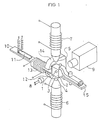
- FIG. 1 is a perspective schematic representation of the main portions of one embodiment of the present invention.
- a movable-piece 1 as a sensing member is a sphere fully or partly composed of magnetic material, for example, soft iron, and is immersed in a viscoelastic sample material 2 sealed hermetically in a sample container 3 with transparent windows.
- Magnet cores 4,5 which is winded with magnet coil 6,7 of, for example, enamelled copper wires composes a pair of electromagnet facing each other.
- a displacement measuring device 9, for example, a non-contact optoelectronic tracker detects the displacement of the image of the movable-piece 1 transmitted by a light beam from a light source 8, for example, an electric lamp.
- the sample container 3 is fixed to the free end of a bracket 10.
- the bracket 10 is a cantilever of an elastic substance, for example, phosphor bronze, and equipped with a displacement measuring device 11, for example, an electric resistance wire strain gauge which detects the displacement of the sample container 3.
- a magnetic plate 12 is fixed near the free end of the bracket 10, and the sample container 3 vibrates vertically in the co-axial direction between the pair of magnet cores 4,5.
- a container clump 15 is used in moving probe mode when only the movable-piece is reciprocated but the container 3 is fixed.
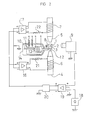
- Fig. 2 is a diagram of the electric circuit of one embodiment of the present invention.
- Driving currents are supplied to the magnet coils 6,7 by D.C. power amplifiers 16,17.
- Resistors 21,22 detects coil currents of the magnet coils 6,7 respectively.
- the servomechanism of a preferred embodiment of the present invention consists as follows.
- a displacement measuring device 9 produces a signal voltage proportional to the displacement of said movable-piece 1.
- a signal voltage which indicates position or motion to be followed is introduced by a wave generator 18.
- An operational amplifier 19 produces a signal voltage indicating the dislocation of said movable-piece 1 at the instance with a reference standard signal voltage indicating an intended position, and produces a differential signal voltage, which is fed into D.C. power amplifiers 16,17, and they supply drive currents to the magnet coils 7,8, and reduce deviation of the movable-piece 1 off from intended position.
- a compensation circuit 20 consists of, for example, P(proportional), l(integral), D(differential) circuits and provides quick response and good stability of the servo-system.
- any type of means for non-contact displacement measurement can be employed.
- other devices can be used such as conventional devices for displacement measurement employing photoelectric principles, for example a photocell and a photodiode, conventional devices using radiant rays, electromagnetic waves, for example, using X-rays or gamma-rays and ultrasonic waves.
- a contact manner For sensing of the position of the sample container 3, comparatively bulky methods in a contact manner can be also applied.
- They are an electromagnetic device, for example, a pick-up coil or a differential transformer, an electrocapaci- tance device and an electric resistance wire strain gauge.
- a sphere is preferable, because it is symmetrical in every direction, mechanically strong, easy to be manufactured and convenient to analyse as a theoretical model.
- parallel motion of a needle, a strip or a plate, or rotational motion of a column, a cylinder, a cone or a disc may be also appliable.
- a moment is produced by magnetic drive unit with its magnetic poles placed in a tangential direction on a magnetic tip to the rim of the disc-shaped movable-piece.
- Another method is a circular arrangement of electric field magnets around the movable-piece 1, which generates rotational magnetic field and produces a moment by an induction effect.
- Those are well known conventional methods used in electric rotary machines. Detection of the position or motion of a movable-piece is also capable at the same point where the magnetic force works.
- supplementary supporting elements for example rotary bearings such as a magnetic bearing, a fluid bearing or a mechanical bearing may be additionary used.
- rotary bearings such as a magnetic bearing, a fluid bearing or a mechanical bearing
- the movable-piece 1 may be attached to the sample material 2.
- the movable-piece 1 gives external force on the sample material 1 and produces tension, compression, bending, shearing or torsion in the material. And the relation between the external force and the deformation of the sample yields rheological properties of the sample.
- a signal generator 18 may be so adjusted as to produce the same signal voltage as the output voltage from a displacement measuring device 9 to be expected.
- the embodiment of the invention can be used in either of the two measuring modes, which are a moving container mode and a moving probe mode, by selecting among them.
- a moving container mode the movable-piece 1 is held stationary at the fixed position and a vibrator coil 13 moves the sample container 3.
- a moving probe mode the sample container 3 is held stationary by a container clump 15 and a movable-piece 1 moves according to the signal from a wave generator 18.
- the viscoelastic values of a sample material 2 is determined according to the magnetic force on a movable-piece 1 and relative motion between the movable-piece 1 and the sample material 2.
- the magnetic force can be estimated using voltage drop across resistors 21,22 for a measure of coil currents, but practically it is convenient to perform calibration of the magnetic force by either of the gravitational acceleration on the movable-piece 1 or sinusoidal oscillation of the movable-piece 1 in a Newtonian fluid of known viscosity using the same values for the driving currents.
- a relative displacement between a movable-piece 1 and a sample material 2 is measured in a moving container mode according to the displacement of the sample container 3, and in a moving probe mode according to the motion of the movable-piece 1, that is, according to an output signal voltage from the displacement measuring device 9 respectively.
- the change of magnetic force may be assumed to be proportional to the change of the coil current, when the test frequency is not so high, where
- Complex modulus and viscosity is calculated, for example, using a sphere as a movable-piece 1 and simple oscillation displacement to a viscoelastic material.
- the magnetic force is plotted in horizontal axis and the displacement of the movable-piece 1 is plotted vertical axis on an oscilloscope.
- the magnetic force is measured by current through resistor 22, and the displacement is measured by the displacement measuring device 9 and the Lissadous-loop of them on an oscilloscope results in an ellipse.
- the phase lag of displacement to magnetic force is determined according to the shape of the ellipse.
- the present invention is valuable as an apparatus for rheological measurement and its: simple mechanical structure yields easy manufacture of it and convenient operation. It is useful in such fields as rheological, especially biorheological studies where only a very small amount of sample is available, and in such fields as examination, usage and production of rheological material, because of convenient operation and quick measurement.
Landscapes
- Physics & Mathematics (AREA)
- Health & Medical Sciences (AREA)
- Life Sciences & Earth Sciences (AREA)
- Chemical & Material Sciences (AREA)
- Analytical Chemistry (AREA)
- Biochemistry (AREA)
- General Health & Medical Sciences (AREA)
- General Physics & Mathematics (AREA)
- Immunology (AREA)
- Pathology (AREA)
- Investigating Strength Of Materials By Application Of Mechanical Stress (AREA)
Claims (5)
Priority Applications (1)
| Application Number | Priority Date | Filing Date | Title |
|---|---|---|---|
| AT84902051T ATE36412T1 (de) | 1983-05-31 | 1984-05-14 | Rheometer. |
Applications Claiming Priority (4)
| Application Number | Priority Date | Filing Date | Title |
|---|---|---|---|
| JP96700/83 | 1983-05-31 | ||
| JP9670083A JPS59221639A (ja) | 1983-05-31 | 1983-05-31 | 粘度計 |
| JP3483884A JPS60178336A (ja) | 1984-02-25 | 1984-02-25 | 粘弾性計 |
| JP34838/84 | 1984-02-25 |
Publications (3)
| Publication Number | Publication Date |
|---|---|
| EP0144437A1 EP0144437A1 (de) | 1985-06-19 |
| EP0144437A4 EP0144437A4 (de) | 1985-10-14 |
| EP0144437B1 true EP0144437B1 (de) | 1988-08-10 |
Family
ID=26373702
Family Applications (1)
| Application Number | Title | Priority Date | Filing Date |
|---|---|---|---|
| EP84902051A Expired EP0144437B1 (de) | 1983-05-31 | 1984-05-14 | Rheometer |
Country Status (4)
| Country | Link |
|---|---|
| US (1) | US4602501A (de) |
| EP (1) | EP0144437B1 (de) |
| DE (1) | DE3473351D1 (de) |
| WO (1) | WO1984004812A1 (de) |
Families Citing this family (36)
| Publication number | Priority date | Publication date | Assignee | Title |
|---|---|---|---|---|
| GB8525255D0 (en) * | 1985-10-14 | 1985-11-20 | Ravenfield Designs Ltd | Rheometer |
| US4794788A (en) * | 1987-10-05 | 1989-01-03 | Monsanto Company | Method and apparatus for rheological testing |
| DE3800474A1 (de) * | 1988-01-11 | 1989-07-20 | Basf Lacke & Farben | Verfahren und vorrichtung zum messen der viskositaet von stoffen |
| JPH02157655A (ja) * | 1988-12-09 | 1990-06-18 | Seiko Instr Inc | 反応容器 |
| SE501809C2 (sv) * | 1992-10-05 | 1995-05-22 | Lund Medicinsk Reologi Ab | Sätt att mäta reologiska egenskaper och reometer för genomförande av sättet |
| US5365778A (en) * | 1994-01-28 | 1994-11-22 | The University Of Chicago | Method for measuring liquid viscosity and ultrasonic viscometer |
| AUPM517894A0 (en) * | 1994-04-19 | 1994-05-12 | Commonwealth Scientific And Industrial Research Organisation | Viscosity measurement device |
| IL114494A0 (en) * | 1995-07-06 | 1995-11-27 | Te Eni Moshe | System and method for controlling concrete production |
| DE19733114C2 (de) * | 1997-07-31 | 1999-08-05 | Max Planck Gesellschaft | Verfahren und Vorrichtung zur Erfassung rheologischer Materialeigenschaften |
| US6227039B1 (en) * | 1998-01-06 | 2001-05-08 | Moshe Te'eni | System and method for controlling concrete production |
| US6393898B1 (en) | 2000-05-25 | 2002-05-28 | Symyx Technologies, Inc. | High throughput viscometer and method of using same |
| US6664067B1 (en) | 2000-05-26 | 2003-12-16 | Symyx Technologies, Inc. | Instrument for high throughput measurement of material physical properties and method of using same |
| US6484567B1 (en) | 2000-08-03 | 2002-11-26 | Symyx Technologies, Inc. | Rheometer for rapidly measuring small quantity samples |
| SE0100918D0 (sv) * | 2001-03-16 | 2001-03-16 | Global Hemostasis Inst Mgr Ab | Rod provided with channel |
| US6772642B2 (en) | 2001-08-24 | 2004-08-10 | Damian A. Hajduk | High throughput mechanical property and bulge testing of materials libraries |
| US6650102B2 (en) | 2001-08-24 | 2003-11-18 | Symyx Technologies, Inc. | High throughput mechanical property testing of materials libraries using a piezoelectric |
| US6769292B2 (en) * | 2001-08-24 | 2004-08-03 | Symyx Technologies, Inc | High throughput rheological testing of materials |
| US6736017B2 (en) | 2001-08-24 | 2004-05-18 | Symyx Technologies, Inc. | High throughput mechanical rapid serial property testing of materials libraries |
| US6837115B2 (en) * | 2001-08-24 | 2005-01-04 | Symyx Technologies, Inc. | High throughput mechanical rapid serial property testing of materials libraries |
| US6857309B2 (en) | 2001-08-24 | 2005-02-22 | Symyx Technologies, Inc. | High throughput mechanical rapid serial property testing of materials libraries |
| US6860148B2 (en) | 2001-08-24 | 2005-03-01 | Symyx Technologies, Inc. | High throughput fabric handle screening |
| US6690179B2 (en) * | 2001-08-24 | 2004-02-10 | Symyx Technologies, Inc. | High throughput mechanical property testing of materials libraries using capacitance |
| US20030055587A1 (en) * | 2001-09-17 | 2003-03-20 | Symyx Technologies, Inc. | Rapid throughput surface topographical analysis |
| US7013709B2 (en) * | 2002-01-31 | 2006-03-21 | Symyx Technologies, Inc. | High throughput preparation and analysis of plastically shaped material samples |
| US20030203500A1 (en) * | 2002-04-26 | 2003-10-30 | Symyx Technologies, Inc. | High throughput testing of fluid samples using an electric field |
| US7112443B2 (en) * | 2002-10-18 | 2006-09-26 | Symyx Technologies, Inc. | High throughput permeability testing of materials libraries |
| US6952950B2 (en) * | 2003-03-07 | 2005-10-11 | Waters Investment Limited | System and method for automatic identification of a detachable component of an instrument |
| US6798099B1 (en) | 2003-07-14 | 2004-09-28 | Waters Investment Limited | Devices, systems and methods for sensing temperature of a drag cup in a rheometer motor |
| US7500385B2 (en) * | 2005-11-23 | 2009-03-10 | Waters Investments Limited | System for in-situ optical measurement and sample heating during rheometric measurements |
| US7594429B2 (en) * | 2005-11-23 | 2009-09-29 | Waters Investments Limited | System and method for improved optical measurements during rheometric measurements |
| US8056398B2 (en) * | 2008-02-19 | 2011-11-15 | Kent State University | Broad-range nanoliter rheometer |
| ITPN20090047A1 (it) * | 2009-09-02 | 2011-03-03 | Re Andrea Da | Sistemi di misura di analizzatori dinamico meccanici per materiali a bassa viscosita' |
| US9851286B2 (en) * | 2012-03-13 | 2017-12-26 | Vibrac, Llc | Viscosity testing system and method of using the same |
| CN105973976A (zh) * | 2016-07-20 | 2016-09-28 | 重庆鼎润医疗器械有限责任公司 | 磁悬浮血栓弹力图仪 |
| KR20200095458A (ko) * | 2017-12-01 | 2020-08-10 | 하마마츠 포토닉스 가부시키가이샤 | 액추에이터 장치 |
| JP6585147B2 (ja) * | 2017-12-01 | 2019-10-02 | 浜松ホトニクス株式会社 | アクチュエータ装置 |
Family Cites Families (8)
| Publication number | Priority date | Publication date | Assignee | Title |
|---|---|---|---|---|
| US2957338A (en) * | 1957-11-29 | 1960-10-25 | Great Lakes Carbon Corp | Viscometer |
| US3967934A (en) * | 1969-06-13 | 1976-07-06 | Baxter Laboratories, Inc. | Prothrombin timer |
| US3695842A (en) * | 1970-03-12 | 1972-10-03 | Intern Technidyne Corp | Method and system for analyzing a liquid |
| JPS51131385A (en) * | 1975-05-10 | 1976-11-15 | Suga Shikenki Kk | Gel timer |
| JPS5526766A (en) * | 1978-08-15 | 1980-02-26 | Nec Corp | Terminal-circuit-side transmitter circuit of repeater |
| DE2908469A1 (de) * | 1979-03-05 | 1980-09-11 | Fresenius Chem Pharm Ind | Verfahren und vorrichtung zur bestimmung der visko-elastischen eigenschaften von fluiden |
| SU842486A1 (ru) * | 1979-09-20 | 1981-06-30 | Ташкентский Политехнический Институтим.Беруни | Изменитель в зкости |
| SU1081474A1 (ru) * | 1982-12-30 | 1984-03-23 | Научно-Исследовательская Лаборатория Физико-Химической Механики Материалов И Технологических Процессов Главмоспромстройматериалов | Способ определени в зкости пластично-в зких смесей |
-
1984
- 1984-05-14 EP EP84902051A patent/EP0144437B1/de not_active Expired
- 1984-05-14 DE DE8484902051T patent/DE3473351D1/de not_active Expired
- 1984-05-14 US US06/700,708 patent/US4602501A/en not_active Expired - Lifetime
- 1984-05-14 WO PCT/JP1984/000241 patent/WO1984004812A1/ja not_active Ceased
Also Published As
| Publication number | Publication date |
|---|---|
| DE3473351D1 (en) | 1988-09-15 |
| EP0144437A4 (de) | 1985-10-14 |
| US4602501A (en) | 1986-07-29 |
| WO1984004812A1 (en) | 1984-12-06 |
| EP0144437A1 (de) | 1985-06-19 |
Similar Documents
| Publication | Publication Date | Title |
|---|---|---|
| EP0144437B1 (de) | Rheometer | |
| US4679427A (en) | Apparatus for measuring viscosity | |
| KR920003532B1 (ko) | 진동레오미터장치 | |
| Luo et al. | Determination of the Newtonian gravitational constant G with a nonlinear fitting method | |
| CA1282252C (en) | Tuning fork vibration-type viscosity measuring apparatus | |
| EP0611448B1 (de) | Vorrichtung zur bestimmung der viskoelastischen eigenschaften von flüssigkeiten und methode zu deren anwendung | |
| McConnaughey et al. | Cell poker: An apparatus for stress‐strain measurements on living cells | |
| US2696735A (en) | Vibrating plate viscometer | |
| US5987970A (en) | Rotational viscosity measurement apparatus | |
| US5040410A (en) | Rheometer | |
| US4763512A (en) | Rheometer | |
| RU2419781C2 (ru) | Вибровискозиметрический датчик | |
| US3498104A (en) | Automatic pour point analyzer | |
| US3474658A (en) | Thermomechanical analyzer | |
| JPS5915837A (ja) | 高温流体の粘度測定装置 | |
| US2419217A (en) | Weighing apparatus | |
| Morrisson et al. | Apparatus for Low‐Frequency Dynamic Measurement on Polymeric Systems | |
| US6639403B2 (en) | System and method for sensing magnetic fields based on movement | |
| Marshall et al. | A capacitance depth gauge for thin liquid films | |
| US3696661A (en) | Method and apparatus for measuring the yield stress of non-newtonian fluids | |
| US4448057A (en) | Apparatus and method for testing a geophone during assembly | |
| US20030038627A1 (en) | Electromechanical drive for magnetometers | |
| SU1744593A1 (ru) | Вибрационный вискозиметр | |
| GB2231154A (en) | Apparatus and method for determining powder characteristics | |
| Hargens | Portable Liquid Density Instrument Employing Transistors |
Legal Events
| Date | Code | Title | Description |
|---|---|---|---|
| PUAI | Public reference made under article 153(3) epc to a published international application that has entered the european phase |
Free format text: ORIGINAL CODE: 0009012 |
|
| 17P | Request for examination filed |
Effective date: 19850205 |
|
| AK | Designated contracting states |
Designated state(s): AT BE CH DE FR GB LI LU NL SE |
|
| 17Q | First examination report despatched |
Effective date: 19870513 |
|
| GRAA | (expected) grant |
Free format text: ORIGINAL CODE: 0009210 |
|
| AK | Designated contracting states |
Kind code of ref document: B1 Designated state(s): AT BE CH DE FR GB LI LU NL SE |
|
| PG25 | Lapsed in a contracting state [announced via postgrant information from national office to epo] |
Ref country code: SE Effective date: 19880810 Ref country code: NL Effective date: 19880810 Ref country code: BE Effective date: 19880810 Ref country code: AT Effective date: 19880810 |
|
| REF | Corresponds to: |
Ref document number: 36412 Country of ref document: AT Date of ref document: 19880815 Kind code of ref document: T |
|
| REF | Corresponds to: |
Ref document number: 3473351 Country of ref document: DE Date of ref document: 19880915 |
|
| ET | Fr: translation filed | ||
| NLV1 | Nl: lapsed or annulled due to failure to fulfill the requirements of art. 29p and 29m of the patents act | ||
| PG25 | Lapsed in a contracting state [announced via postgrant information from national office to epo] |
Ref country code: LU Free format text: LAPSE BECAUSE OF NON-PAYMENT OF DUE FEES Effective date: 19890531 |
|
| PLBE | No opposition filed within time limit |
Free format text: ORIGINAL CODE: 0009261 |
|
| STAA | Information on the status of an ep patent application or granted ep patent |
Free format text: STATUS: NO OPPOSITION FILED WITHIN TIME LIMIT |
|
| 26N | No opposition filed | ||
| PGFP | Annual fee paid to national office [announced via postgrant information from national office to epo] |
Ref country code: GB Payment date: 19910503 Year of fee payment: 8 |
|
| PGFP | Annual fee paid to national office [announced via postgrant information from national office to epo] |
Ref country code: FR Payment date: 19910524 Year of fee payment: 8 |
|
| PG25 | Lapsed in a contracting state [announced via postgrant information from national office to epo] |
Ref country code: GB Effective date: 19920514 |
|
| GBPC | Gb: european patent ceased through non-payment of renewal fee |
Effective date: 19920514 |
|
| PG25 | Lapsed in a contracting state [announced via postgrant information from national office to epo] |
Ref country code: FR Effective date: 19930129 |
|
| REG | Reference to a national code |
Ref country code: FR Ref legal event code: ST |
|
| PGFP | Annual fee paid to national office [announced via postgrant information from national office to epo] |
Ref country code: DE Payment date: 19950627 Year of fee payment: 12 |
|
| PGFP | Annual fee paid to national office [announced via postgrant information from national office to epo] |
Ref country code: CH Payment date: 19950828 Year of fee payment: 12 |
|
| PG25 | Lapsed in a contracting state [announced via postgrant information from national office to epo] |
Ref country code: LI Effective date: 19960531 Ref country code: CH Effective date: 19960531 |
|
| REG | Reference to a national code |
Ref country code: CH Ref legal event code: PL |
|
| PG25 | Lapsed in a contracting state [announced via postgrant information from national office to epo] |
Ref country code: DE Effective date: 19970201 |