EP0144524A2 - Pompe getter pour installations à vide élevé et à décharge au gaz - Google Patents
Pompe getter pour installations à vide élevé et à décharge au gaz Download PDFInfo
- Publication number
- EP0144524A2 EP0144524A2 EP84109514A EP84109514A EP0144524A2 EP 0144524 A2 EP0144524 A2 EP 0144524A2 EP 84109514 A EP84109514 A EP 84109514A EP 84109514 A EP84109514 A EP 84109514A EP 0144524 A2 EP0144524 A2 EP 0144524A2
- Authority
- EP
- European Patent Office
- Prior art keywords
- getter
- pump
- heating elements
- gas discharge
- getter pump
- Prior art date
- Legal status (The legal status is an assumption and is not a legal conclusion. Google has not performed a legal analysis and makes no representation as to the accuracy of the status listed.)
- Withdrawn
Links
Images

Classifications
-
- H—ELECTRICITY
- H01—ELECTRIC ELEMENTS
- H01J—ELECTRIC DISCHARGE TUBES OR DISCHARGE LAMPS
- H01J7/00—Details not provided for in the preceding groups and common to two or more basic types of discharge tubes or lamps
- H01J7/14—Means for obtaining or maintaining the desired pressure within the vessel
- H01J7/18—Means for absorbing or adsorbing gas, e.g. by gettering
-
- F—MECHANICAL ENGINEERING; LIGHTING; HEATING; WEAPONS; BLASTING
- F04—POSITIVE - DISPLACEMENT MACHINES FOR LIQUIDS; PUMPS FOR LIQUIDS OR ELASTIC FLUIDS
- F04B—POSITIVE-DISPLACEMENT MACHINES FOR LIQUIDS; PUMPS
- F04B37/00—Pumps having pertinent characteristics not provided for in, or of interest apart from, groups F04B25/00 - F04B35/00
- F04B37/02—Pumps having pertinent characteristics not provided for in, or of interest apart from, groups F04B25/00 - F04B35/00 for evacuating by absorption or adsorption
Definitions
- the invention relates to a getter pump for high vacuum and gas discharge systems with getter bodies made of non-evaporating getter material and associated heating elements arranged in a pump vessel.
- the working temperature either had to be varied or the individual getters had to be kept at different temperatures with at least two heating circuits.
- the invention has for its object to increase the specific performance of getter pumps and in particular to enable the production of a high vacuum in the pressure range from 10 -3 mbar and better by non-evaporating getters.
- a getter pump according to the invention has the advantage that very high redundancy is achieved by arranging many getters in the pump vessel.
- the individual getters are designed in such a way that they can be reactivated practically as often as required, even after the pump has been vented.
- the getter pump works either after activation (700 to 1200 ° C) at ambient temperature, i.e. H. with the heating circuit switched off, or it works at an optimal temperature (conditioning temperature of approx. 100 to 700 ° C).
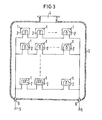
- the getter pumps shown in FIGS. 1 to 3 essentially consist of several getter bodies 1 provided with heating elements 2, which are arranged in a pump vessel 3 provided with a pump flange 4.
- the pump vessel 3 is preferably made of V2A steel.
- the heating elements are connected in parallel.
- a plurality of heating elements 2 are connected in series in groups and the groups in turn are connected in parallel.
- Fig. 4 shows an embodiment in which the pump vessel 3 is not shown.
- the optimal effectiveness e.g. of the zircon getter 1 is achieved when the temperature-dependent selectivity of the material is used.
- the embodiment according to FIG. 2 allows the optimal operating conditions to be set separately for each getter group.
Landscapes
- Engineering & Computer Science (AREA)
- Mechanical Engineering (AREA)
- General Engineering & Computer Science (AREA)
- Compressors, Vaccum Pumps And Other Relevant Systems (AREA)
Applications Claiming Priority (2)
| Application Number | Priority Date | Filing Date | Title |
|---|---|---|---|
| DE3332608 | 1983-09-09 | ||
| DE19833332608 DE3332608A1 (de) | 1983-09-09 | 1983-09-09 | Getter-pumpe fuer hochvakuum- und gasentladungsanlagen |
Publications (2)
| Publication Number | Publication Date |
|---|---|
| EP0144524A2 true EP0144524A2 (fr) | 1985-06-19 |
| EP0144524A3 EP0144524A3 (fr) | 1986-10-08 |
Family
ID=6208668
Family Applications (1)
| Application Number | Title | Priority Date | Filing Date |
|---|---|---|---|
| EP84109514A Withdrawn EP0144524A3 (fr) | 1983-09-09 | 1984-08-09 | Pompe getter pour installations à vide élevé et à décharge au gaz |
Country Status (2)
| Country | Link |
|---|---|
| EP (1) | EP0144524A3 (fr) |
| DE (1) | DE3332608A1 (fr) |
Cited By (1)
| Publication number | Priority date | Publication date | Assignee | Title |
|---|---|---|---|---|
| EP0297061A3 (en) * | 1987-06-24 | 1989-10-18 | Saes Getters S.P.A. | Vacuum insulated electrical conductor employing a getter device |
Families Citing this family (1)
| Publication number | Priority date | Publication date | Assignee | Title |
|---|---|---|---|---|
| IT1295340B1 (it) * | 1997-10-15 | 1999-05-12 | Getters Spa | Pompa getter ad elevata velocita' di assorbimento di gas |
Family Cites Families (3)
| Publication number | Priority date | Publication date | Assignee | Title |
|---|---|---|---|---|
| US2988265A (en) * | 1958-03-21 | 1961-06-13 | Nat Res Corp | Vacuum device |
| IT963874B (it) * | 1972-08-10 | 1974-01-21 | Getters Spa | Dispositivo getter perfezionato contenente materiale non evapora bile |
| US4137012A (en) * | 1976-11-03 | 1979-01-30 | S.A.E.S. Getters S.P.A. | Modular getter pumps |
-
1983
- 1983-09-09 DE DE19833332608 patent/DE3332608A1/de not_active Withdrawn
-
1984
- 1984-08-09 EP EP84109514A patent/EP0144524A3/fr not_active Withdrawn
Cited By (1)
| Publication number | Priority date | Publication date | Assignee | Title |
|---|---|---|---|---|
| EP0297061A3 (en) * | 1987-06-24 | 1989-10-18 | Saes Getters S.P.A. | Vacuum insulated electrical conductor employing a getter device |
Also Published As
| Publication number | Publication date |
|---|---|
| EP0144524A3 (fr) | 1986-10-08 |
| DE3332608A1 (de) | 1985-03-28 |
Similar Documents
| Publication | Publication Date | Title |
|---|---|---|
| DE60202340T2 (de) | Vakuumpumpen | |
| DE2446833C2 (de) | Getterpumpe zum Pumpen von Methan | |
| DE3242730A1 (de) | Abstandshalter fuer leiterplatten und zusammengebaute leiterplattenanordnung | |
| EP1090231A1 (fr) | Pompe a vide rotative munie d'un chassis, d'un rotor et d'un carter, et dispositif pourvu d'une pompe a vide rotative de ce type | |
| CH677009A5 (fr) | ||
| EP2002874B1 (fr) | Dispositif de filtration | |
| EP0144524A2 (fr) | Pompe getter pour installations à vide élevé et à décharge au gaz | |
| EP0846866B1 (fr) | Compresseur pour gaz contenant du sulfure hydrogène | |
| EP1130269B1 (fr) | Pompe turbo-moléculaire | |
| DE102019004450B4 (de) | Mikropumpensystem und Verfahren zur Führung eines kompressiblen Fluids | |
| CH653746A5 (de) | Kryogenpumpe mit strahlungsschutzschild. | |
| DE9217133U1 (de) | Überspannungsableiter mit einem Metalloxid-Widerstand | |
| DE3608289C2 (fr) | ||
| DD157889A5 (de) | Verfahren zur katalytischen gasreinigung | |
| EP0146685A2 (fr) | Pompe getter à sorption ayant un accumulateur de chaleur pour installations à vide élevé et à décharge au gaz | |
| DE2044277A1 (de) | Verfahren zum hermetischen Abdichten und Evakuieren \on Vakuumgehausen | |
| DE3116710C2 (de) | Verfahren zur Regelung der Kühldampfmenge für den Niederdruckteil einer Entnahme-Kondensations-Turbine | |
| EP4445026B1 (fr) | Compresseur d'hydrogène | |
| DD244797A1 (de) | Einrichtung zur belueftung von vakuumkammern | |
| DE4219268A1 (de) | Anordnung zur Vakuumerzeugung | |
| DE102020101331B4 (de) | Invertervorrichtung mit einer Kühlung | |
| DE102020212957A1 (de) | Pulsationsdämpfer für eine Vorrichtung | |
| DE3631609C2 (de) | Hydraulische Anlage in Kraftfahrzeugen mit einem Druckmittelspeicher | |
| DE102022128021A1 (de) | Blattfeder | |
| DE8207794U1 (de) | Hydraulische Versorgungseinheit |
Legal Events
| Date | Code | Title | Description |
|---|---|---|---|
| PUAI | Public reference made under article 153(3) epc to a published international application that has entered the european phase |
Free format text: ORIGINAL CODE: 0009012 |
|
| AK | Designated contracting states |
Designated state(s): CH DE FR IT LI |
|
| PUAL | Search report despatched |
Free format text: ORIGINAL CODE: 0009013 |
|
| AK | Designated contracting states |
Kind code of ref document: A3 Designated state(s): CH DE FR IT LI |
|
| 17P | Request for examination filed |
Effective date: 19870326 |
|
| 17Q | First examination report despatched |
Effective date: 19870902 |
|
| STAA | Information on the status of an ep patent application or granted ep patent |
Free format text: STATUS: THE APPLICATION HAS BEEN WITHDRAWN |
|
| 18W | Application withdrawn |
Withdrawal date: 19880613 |
|
| RIN1 | Information on inventor provided before grant (corrected) |
Inventor name: HEYNISCH, HINRICH, DR. RER. NAT. DIPL.-PHYS. Inventor name: MAEGDEFESSEL, HEINZ, ING. GRAD. Inventor name: HUEBNER, ERWIN, DR. RER. NAT. |