EP0144562B1 - Procédé de et appareil pour tronçonner des carottes et seuils - Google Patents
Procédé de et appareil pour tronçonner des carottes et seuils Download PDFInfo
- Publication number
- EP0144562B1 EP0144562B1 EP19840110718 EP84110718A EP0144562B1 EP 0144562 B1 EP0144562 B1 EP 0144562B1 EP 19840110718 EP19840110718 EP 19840110718 EP 84110718 A EP84110718 A EP 84110718A EP 0144562 B1 EP0144562 B1 EP 0144562B1
- Authority
- EP
- European Patent Office
- Prior art keywords
- runner
- sprue
- cutter
- feed roller
- chopping
- Prior art date
- Legal status (The legal status is an assumption and is not a legal conclusion. Google has not performed a legal analysis and makes no representation as to the accuracy of the status listed.)
- Expired
Links
Images








Classifications
-
- B—PERFORMING OPERATIONS; TRANSPORTING
- B02—CRUSHING, PULVERISING, OR DISINTEGRATING; PREPARATORY TREATMENT OF GRAIN FOR MILLING
- B02C—CRUSHING, PULVERISING, OR DISINTEGRATING IN GENERAL; MILLING GRAIN
- B02C18/00—Disintegrating by knives or other cutting or tearing members which chop material into fragments
- B02C18/02—Disintegrating by knives or other cutting or tearing members which chop material into fragments with reciprocating knives
-
- B—PERFORMING OPERATIONS; TRANSPORTING
- B29—WORKING OF PLASTICS; WORKING OF SUBSTANCES IN A PLASTIC STATE IN GENERAL
- B29C—SHAPING OR JOINING OF PLASTICS; SHAPING OF MATERIAL IN A PLASTIC STATE, NOT OTHERWISE PROVIDED FOR; AFTER-TREATMENT OF THE SHAPED PRODUCTS, e.g. REPAIRING
- B29C45/00—Injection moulding, i.e. forcing the required volume of moulding material through a nozzle into a closed mould; Apparatus therefor
- B29C45/17—Component parts, details or accessories; Auxiliary operations
- B29C45/38—Cutting-off equipment for sprues or ingates
-
- B—PERFORMING OPERATIONS; TRANSPORTING
- B26—HAND CUTTING TOOLS; CUTTING; SEVERING
- B26D—CUTTING; DETAILS COMMON TO MACHINES FOR PERFORATING, PUNCHING, CUTTING-OUT, STAMPING-OUT OR SEVERING
- B26D9/00—Cutting apparatus combined with punching or perforating apparatus or with dissimilar cutting apparatus
-
- B—PERFORMING OPERATIONS; TRANSPORTING
- B29—WORKING OF PLASTICS; WORKING OF SUBSTANCES IN A PLASTIC STATE IN GENERAL
- B29B—PREPARATION OR PRETREATMENT OF THE MATERIAL TO BE SHAPED; MAKING GRANULES OR PREFORMS; RECOVERY OF PLASTICS OR OTHER CONSTITUENTS OF WASTE MATERIAL CONTAINING PLASTICS
- B29B11/00—Making preforms
- B29B11/06—Making preforms by moulding the material
- B29B11/08—Injection moulding
-
- B—PERFORMING OPERATIONS; TRANSPORTING
- B29—WORKING OF PLASTICS; WORKING OF SUBSTANCES IN A PLASTIC STATE IN GENERAL
- B29B—PREPARATION OR PRETREATMENT OF THE MATERIAL TO BE SHAPED; MAKING GRANULES OR PREFORMS; RECOVERY OF PLASTICS OR OTHER CONSTITUENTS OF WASTE MATERIAL CONTAINING PLASTICS
- B29B13/00—Conditioning or physical treatment of the material to be shaped
- B29B13/10—Conditioning or physical treatment of the material to be shaped by grinding, e.g. by triturating; by sieving; by filtering
-
- B—PERFORMING OPERATIONS; TRANSPORTING
- B29—WORKING OF PLASTICS; WORKING OF SUBSTANCES IN A PLASTIC STATE IN GENERAL
- B29C—SHAPING OR JOINING OF PLASTICS; SHAPING OF MATERIAL IN A PLASTIC STATE, NOT OTHERWISE PROVIDED FOR; AFTER-TREATMENT OF THE SHAPED PRODUCTS, e.g. REPAIRING
- B29C45/00—Injection moulding, i.e. forcing the required volume of moulding material through a nozzle into a closed mould; Apparatus therefor
- B29C45/17—Component parts, details or accessories; Auxiliary operations
- B29C45/1769—Handling of moulded articles or runners, e.g. sorting, stacking, grinding of runners
-
- B—PERFORMING OPERATIONS; TRANSPORTING
- B29—WORKING OF PLASTICS; WORKING OF SUBSTANCES IN A PLASTIC STATE IN GENERAL
- B29C—SHAPING OR JOINING OF PLASTICS; SHAPING OF MATERIAL IN A PLASTIC STATE, NOT OTHERWISE PROVIDED FOR; AFTER-TREATMENT OF THE SHAPED PRODUCTS, e.g. REPAIRING
- B29C31/00—Handling, e.g. feeding of the material to be shaped, storage of plastics material before moulding; Automation, i.e. automated handling lines in plastics processing plants, e.g. using manipulators or robots
-
- Y—GENERAL TAGGING OF NEW TECHNOLOGICAL DEVELOPMENTS; GENERAL TAGGING OF CROSS-SECTIONAL TECHNOLOGIES SPANNING OVER SEVERAL SECTIONS OF THE IPC; TECHNICAL SUBJECTS COVERED BY FORMER USPC CROSS-REFERENCE ART COLLECTIONS [XRACs] AND DIGESTS
- Y10—TECHNICAL SUBJECTS COVERED BY FORMER USPC
- Y10S—TECHNICAL SUBJECTS COVERED BY FORMER USPC CROSS-REFERENCE ART COLLECTIONS [XRACs] AND DIGESTS
- Y10S425/00—Plastic article or earthenware shaping or treating: apparatus
- Y10S425/034—Morin
-
- Y—GENERAL TAGGING OF NEW TECHNOLOGICAL DEVELOPMENTS; GENERAL TAGGING OF CROSS-SECTIONAL TECHNOLOGIES SPANNING OVER SEVERAL SECTIONS OF THE IPC; TECHNICAL SUBJECTS COVERED BY FORMER USPC CROSS-REFERENCE ART COLLECTIONS [XRACs] AND DIGESTS
- Y10—TECHNICAL SUBJECTS COVERED BY FORMER USPC
- Y10S—TECHNICAL SUBJECTS COVERED BY FORMER USPC CROSS-REFERENCE ART COLLECTIONS [XRACs] AND DIGESTS
- Y10S425/00—Plastic article or earthenware shaping or treating: apparatus
- Y10S425/046—Scrap
-
- Y—GENERAL TAGGING OF NEW TECHNOLOGICAL DEVELOPMENTS; GENERAL TAGGING OF CROSS-SECTIONAL TECHNOLOGIES SPANNING OVER SEVERAL SECTIONS OF THE IPC; TECHNICAL SUBJECTS COVERED BY FORMER USPC CROSS-REFERENCE ART COLLECTIONS [XRACs] AND DIGESTS
- Y10—TECHNICAL SUBJECTS COVERED BY FORMER USPC
- Y10S—TECHNICAL SUBJECTS COVERED BY FORMER USPC CROSS-REFERENCE ART COLLECTIONS [XRACs] AND DIGESTS
- Y10S425/00—Plastic article or earthenware shaping or treating: apparatus
- Y10S425/051—Sprue removal
-
- Y—GENERAL TAGGING OF NEW TECHNOLOGICAL DEVELOPMENTS; GENERAL TAGGING OF CROSS-SECTIONAL TECHNOLOGIES SPANNING OVER SEVERAL SECTIONS OF THE IPC; TECHNICAL SUBJECTS COVERED BY FORMER USPC CROSS-REFERENCE ART COLLECTIONS [XRACs] AND DIGESTS
- Y10—TECHNICAL SUBJECTS COVERED BY FORMER USPC
- Y10S—TECHNICAL SUBJECTS COVERED BY FORMER USPC CROSS-REFERENCE ART COLLECTIONS [XRACs] AND DIGESTS
- Y10S425/00—Plastic article or earthenware shaping or treating: apparatus
- Y10S425/814—Zipper
-
- Y—GENERAL TAGGING OF NEW TECHNOLOGICAL DEVELOPMENTS; GENERAL TAGGING OF CROSS-SECTIONAL TECHNOLOGIES SPANNING OVER SEVERAL SECTIONS OF THE IPC; TECHNICAL SUBJECTS COVERED BY FORMER USPC CROSS-REFERENCE ART COLLECTIONS [XRACs] AND DIGESTS
- Y10—TECHNICAL SUBJECTS COVERED BY FORMER USPC
- Y10S—TECHNICAL SUBJECTS COVERED BY FORMER USPC CROSS-REFERENCE ART COLLECTIONS [XRACs] AND DIGESTS
- Y10S83/00—Cutting
- Y10S83/923—Waste product cutting
-
- Y—GENERAL TAGGING OF NEW TECHNOLOGICAL DEVELOPMENTS; GENERAL TAGGING OF CROSS-SECTIONAL TECHNOLOGIES SPANNING OVER SEVERAL SECTIONS OF THE IPC; TECHNICAL SUBJECTS COVERED BY FORMER USPC CROSS-REFERENCE ART COLLECTIONS [XRACs] AND DIGESTS
- Y10—TECHNICAL SUBJECTS COVERED BY FORMER USPC
- Y10T—TECHNICAL SUBJECTS COVERED BY FORMER US CLASSIFICATION
- Y10T83/00—Cutting
- Y10T83/04—Processes
- Y10T83/0524—Plural cutting steps
Definitions
- the present invention relates to a method of chopping a runner structure composed of a runner connecting injection-molded articles and a sprue (b) discharged from an injection molding machine, said method comprising the steps of: guiding the runner structure discharged from the injection molding machine, separating the injection-molded articles off the runner structure as guided; chopping the runner structure to chips; and delivering said chips into the injection molding machine for recycling.
- the present invention further relates to an apparatus for chopping a runner structure composed of a runner connecting injection-molded articles and a sprue discharged from an injection molding machine, said apparatus comprising: a guide mechanism for guiding the runner structure discharged from the injection molding machine; a feeding mechanism feeding the runner structure; and a separation mechanism for separating the injection-molded articles off the runner structure.
- the prior chopping process requires two devices, the cutter and the crusher, and an expenditure of manual holder for carrying the broken pieces from the cutter to the crusher and operating the crusher.
- the crusher scatters around the chopped pieces resulting in a loss of usable material and contaminate surroundings with the scattered chips.
- the cutter and the crusher have to be cleaned.
- the present invention seeks to provide a method of automatically chopping runners and sprues discharged from an injection molding machine into pieces for reuse.
- the present invention further seeks to provide an apparatus of a simple construction for automatically chopping runners and sprues discharged from an injection molding machine into pieces for reuse.
- Figures 1 and 2 illustrate a runner structure A cut off a slide fastener stringer chain on which coupling elements are injection-molded of synthetic resin. Since the injection molding machine for molding the coupling elements has a main feed channel called a sprue and a feed channel called a runner connecting the sprue to mold cavity gates, the runner structure A also has a runner a and a sprue b projecting substantially perpendic.ularly from the runner a.
- a runner chopping apparatus 10 for chopping the runner structure A generally includes a guide mechanism 11 for guiding the runner structure A downwardly, a first cutter mechanism 12 for cutting off the sprue b off the runner a, a second cutter mechanism 13 for cutting the runner a as guided by the guide mechanism 11 into smaller pieces, and a pusher mechanism 14 actuatable when the sprue b is severed.
- the runner chopping apparatus 10 is disposed below a roller pair 15 for separating the runner structure A from a slide fastener stringer chain 18 as discharged from molds 17 in an injection molding machine.
- the guide mechanism 11 serves to allow the runner structure A from the roller pair 15 to go downwardly by gravity, and has a guide base plate 20, a guide cover 21, and a sprue receiver 22, as shown in Figure 4.
- the guide base plate 20 comprises a flat plate wider than the runner structure A and having an upper slant surface 23.
- the guide base plate 20 has a lower horizontal flange fastened by screws to support walls 52 mounted on a support base 16.
- the guide cover 21 is mounted on an upper portion of the guide base plate 20 closely to the slanted surface 23.
- the guide cover 21 is composed of a pair of longitudinal parallel side walls 24 and a front wall 25 interconnecting the side walls 24 at their upper front edges.
- the side walls 24 are progressively wider toward their upper ends and spaced from each other by a distance slightly greater than the width of the runner structure A.
- the front wall 25 is inclined downwardly toward the guide base plate 20, such that the front wall 25, the side walls 24, and the slanted surface 23 jointly constitute a hopper-shaped runner receiver.
- the guide cover 21 and the guide base plate 20 are jointly of a channel-shaped cross section opening laterally below the front wall 25 for passage of the sprue b of the runner structure A as it is guided down the guide cover 21.
- the lower edge of the front wall 25 is spaced from the guide base plate 20 by distance greater than the length of the sprue b, so that the runner A will go downwardly without the sprue b interfering with the front wall 25.
- the sprue receiver 22 is mounted on the guide base plate 20 on the side thereof on which the guide cover 21 is mounted.
- the sprue receiver 22 is composed of a pair of longitudinal parallel side walls 26 and a front wall 27 interconnecting the side walls 26 along their entire front edges.
- the side walls 26, the front wall 27, and the guide base plate 20 jointly serve as a hopper.
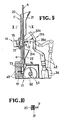
- the first cutter mechanism 12 comprises a swingable arm 30, a lower cutter 31 mounted on an upper end of the swingable arm 30, an upper cutter 32 pivotally coupled to the lower cutter 31, an air cylinder 33 for swinging the arm 30, and an air cylinder 34 for moving the upper cutter 32 toward and away from the lower cutter 31.
- the arm 30 is pivotally mounted on support members 35 fastened by screws to the support base 16.
- the arm 30 is angularly moved by the air cylinder 33 to move cutter edges 36, 37 of the cutters 31, 32 toward and away from a position vertically between the guide cover 21 and the sprue receiver 22.
- the lower cutter 31 extends normally to the guide base plate 20, and the upper cutter 32 is mounted on the lower cutter 31 by a pivot 38 so as to be angularly movable through an arcuate path with respect to the lower cutter 31.
- a link 39 is pivotally connected at one end to an end of the upper cutter 32 remote from the cutter edge 37, and has an opposite end pivotally coupled to a piston rod 42 of the air cylinder 34.
- the upper cutter 32 has a stopper 40 which prevents the upper cutter 32 from turning beyond the lower cutter 31 when the cutter edges 37, 36 engage each other.
- the stopper 40 also serves to prevent a cut-off sprue b from being scattered toward the arm 30, but allows the cut-off sprue b to drop into the sprue receiver 22.
- the air cylinder 33 has a piston rod 41 pivotally connected to the arm 30 and a cylinder pivotally connected to the support base 16.
- the air cylinder 34 has its cylinder pivotally mounted on a second support member 44 mounted on a support member 43 pivotally supported on the support members 35 mounted on the support base 16. The air cylinder 34 is thus angularly movable with the arm 30.
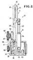
- the second cutter mechanism 13 is disposed below the guide mechanism 11 and has a feed roller 50 for intermittently feeding the runner a as guided by the guide mechanism 11 and a cutter 51 movable toward and away from the feed roller 50 to cut off the runner a.
- the feed roller 50 is fixed to a rotatable shaft 53 rotatably supported by and between a pair of support walls 52 secured to the support base 16.
- the rotatable shaft 53 has opposite ends projecting beyond the support walls 52.
- a ratchet wheel 55 is mounted on one of the projecting ends of the rotatable shaft 53.
- a pawl 54 engages the ratchet wheel 55.
- the pawl 54 and the ratchet wheel 55 jointly constitute a ratchet mechanism.
- a brake mechanism 56 is mounted on the other end of the rotatable shaft 53 for preventing the feed roller 50 from overrun- ing or reversing.
- the pawl 54 is pivotally mounted on a support shaft 48 mounted on a rod 57 movable back and forth by a drive mechanism 60 ( Figure 4).
- the cutter 51 is in the form of a flat plate having a pointed sharp end directed toward the feed roller 50 and supported reciprocably by a cutter support body 49. As shown in Figure 3, the cutter 51 is spaced downwardly from the cutter edge 36 of the lower cutter 31 of the first cutter mechanism 12 by a distance d 1 which is slightly greater than a distance d 2 ( Figures 1 and 2) between the leading end of the runner a and the sprue b.
- the feed roller 50 and the cutter 51 are surrounded by the cutter support body 49, an upper plate 58 of the support base 16, the support walls 52, and a front cover 59 of an inverted L-shaped configuration.
- the drive mechanism 60 comprises a motor 61 mounted in the support base 16, a shaft 63 rotatably supported on supports 62 mounted on the support base 16, and a motion converting mechanism 64, 65 for converting rotary motion of the shaft 63 into reciprocatory motion.
- Rotative power from the motor 61 is transmitted to the shaft 63 through an endless belt 68 trained around a pulley 66 mounted on a motor shaft of the motor 61 and a pulley 67 mounted on the shaft 63.
- the motion converting mechanism 64,65 is composed of circular rotary bodies 69, 70 eccentrically mounted on the shaft 63, and drivers 71,72 rotatabty mounted by bearings on the rotary bodies 69, 70, respectively.
- the driver 71 is pivotally connected to the cutter 51, while the driver 72 is coupled to the rod 57.
- the feed roller 50 is turned about the shaft 53 by the pawl 54 and the ratchet wheel 59 by one angular pitch equal to an interval between adjacent teeth on the ratchet wheel 55 each time the cutter 51 makes one reciprocating movement.
- the rotary bodies 69, 70 are eccentrically mounted on the shaft 63 180° out of phase with each other so thatthe drivers 71,72 move back and forth alternately. Therefore, the feed roller 50 is stopped against rotation when the cutter 51 is advanced toward the feed roller 50, and is angularly moved one pitch when the cutter 51 is retracted away from the feed roller 50.
- a presser 73 for pressing the runner a against the feed roller 50 and a guide 74 for guiding the runner a between the presser 73 and the feed roller 50.
- the presser 73 is pivotally mounted on and disposed between the support walls 52 in confronting relation to the feed roller 50.
- the presser 73 is normally urged to move toward the feed roller 50 underthe force of a spring 75 acting between the presser 73 and the cutter support body 49.
- the runner a as it is delivered toward the feed roller 50 after the sprue b has been severed therefrom is intermittently fed along in synchronism with incremental rotation of the feed roller 50.
- the pusher mechanism 14 serves to displace the runner structure A toward the cutter edges 36, 37 of the cutters 31,32 when the sprue b is to be cut off from the runner structure A by the first cutter mechanism 12.
- the pusher mechanism 14 includes a plunger 76 mounted on a back of the guide base plate 20 and a pusher 77 movable by the plunger 76 toward and away from the cutters 31, 32, the pusher 77 having a flat front surface.
- the plunger 76 remains inactivated, the flat front surface of the pusher 77 lies flush with the front surface of the guide base plate 20.
- the plunger 76 is actuated, the pusher 77 is displaced toward the cutters 31, 32.
- the upper plate 58 of the support base 16 has a hole 78 defined therein for passage therethrough of pieces or chips cut off the runner a by the second cutter mechanism 13.
- a hopper 79 is mounted in the support base 16 below the hole 78 for collecting the chips falling through the hole 78 and delivering them into a box (not shown) or onto a conveyor belt (not shown), from which the chips will be transferred into a hopper of the injection molding machine or pneumatically fed through a transfer pipe into the hopper of the injection molding machine.
- roller pair 15 for separating the runner structure A off the slide fastener chain 18 is known from Japanese Patent Publications 38-20921 and 39-9385, referred to above, and need not be described in detail.
- the distance D between the cutter 51 and the center of the roller pair 15 should be selected to be equal to the length of a series of cavity gates (not shown) in each of the molds 17 or the length of the runner structure A.
- a prior runner structure and a next successive runner will be longitudinally spaced a distance equal to the distance between the center of the roller pair 15 and the lower end of the molds 17 afterthe prior runner structure has fully entered the chopping apparatus 10. Accordingly, two unchopped runner structures will not be simultaneously introduced into the chopping apparatus 10.
- the piston rod 41 in the first cutter mechanism 12 is projected and the piston rod 42 is retracted to displace the upper cutter 32 away from the lower cutter 31 and also from a path of movement of the sprue b of the runner structure A as it is guided by the guide mechanism 11.
- the lower cutter 31 is spaced from the guide base plate 20, but projects into the path of movement of the sprue b to prevent the sprue b from moving downwardly.
- the motor 61 rotates at all times to move the cutter 51 back and forth and at the same time to rotate the feed roller 50 intermittently.
- the runner structure A When the runner structure A is discharged from the roller pair 15, it is guided to move downwardly by the guide mechanism 11. Where the runner structure A is not hardened completely when it is separated by the roller pair 15, the runner a tends to be curved as shown in Figure 4. However, the front wall 25 engages and guides the leading end of the curved runner a toward the guide base plate 20. Accordingly, the runner structure A is fed down the guide mechanism 11 while it is being progressively shaped to proper contour and hardened.
- the plunger 76 Upon engagement between the sprue b and the lower cutter 31, the plunger 76 is energized to displace the pusher 77 laterally from the guide base plate 20 and the piston rod 41 is retracted to tilt the arm 30 for thereby moving the cutters 31, 32 toward the guide base plate 20.
- the runner structure A is now sandwiched between the pusher 77 and the lower cutter 31 as illustrated in Figure 8B.
- the severed sprue b falls into the sprue receiver 22 and remains therein as long as the sprue b is present in the sprue receiver 22.
- the sprue b follows the trailing end of the runner a and moves from the sprue receiver 22 into the second cutter mechanism 13, wherein the sprue b is intermittently fed by the feed roller 50 and chopped into pieces, about 3 mm long, by the cutter 51.
- the piston rod 42 is retracted and the piston rod 41 is projected to bring the cutters 31, 32 to the position of Figure 8A.
- the plunger 76 is de-energized to retract the pusher 77 back into the guide base plate 20.
- the sprue b can be severed from the runner a by the first cutter mechanism 12, and then the runner a and the sprue.b can be chopped automatically by the second cutter mechanism 13, so that both the runner a and the sprue b can be recycled.
- the chopping apparatus is of a relatively simple construction since the runner a and the sprue b can be chopped into pieces by the second cutter mechanism 13 only.
- the chopping apparatus is also advantageous in that the first cutter mechanism 12 serves to both stop the runner structure A and cut off the sprue b from the runner a, and also because the second cutter mechanism 13 serves to both feed the runner a and chop the runner a and the sprue b.
- the chopping apparatus operates automatically to that manual labor is substantially eliminated.
- the second cutter mechanism 13 prevents chips from being scattered around and hence does not produce a loss of material that can be reused.
- the feed roller 50 doubles as a member to bear thereon the runner a as it is chopped, and chips will come off the feed roller 50 when the feed roller 50 is intermittently rotated. Accordingly, it is not necessary to clean the feed roller 50 when differently colored runners are to be chopped.
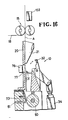
- Figures 9 and 10 show a first cutter mechanism 12a according to another embodiment of the present invention.
- the first cutter mechanism 12a includes a lower cutter 31 a fixed to a frame (not shown) in the path of movement of a sprue b and close to the path of movement of a runner a, and an upper cutter 32a pivotally mounted by a shaft 38a fixed to the frame.
- the sprue b of the runner structure A guided by the guide mechanism 11 is temporarily stopped by engagement with the lower cutter 31a.
- the plunger 76 of the pusher mechanism 14 is energized, the sprue b is sandwiched between the pusher 77 and the lower cutter 21a.
- the piston rod 42 is projected to turn the upper cutter 32a counterclockwise to the position indicated by the two- dot-and-dash line in Figure 9 to cut off the sprue b from the runner a in coaction with the lower cutter 31a.
- the upper cutter 32a then returns to the solid-line position, and the runner a and the sprue b are chopped to pieces by the second cutter mechanism 13.
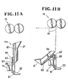
- FIGs 11A and 11B are illustrative of a guide mechanism 11 a according to another embodiment of the invention.
- the guide mechanism 11a a includes a guide base plate composed of an upper plate 80 and a lower plate 81 interconnected by a hinge 82 on rear surfaces thereof, the guide cover 21 being mounted on the upper plate 80.
- the upper and lower plates 80, 81 have staples or locking guides 84, 85, respectively, adjacent to the hinge 82.
- the upper plate 80 is locked in an upright position by a pin 83 extending through and retained in the staples 84, 85, as shown in Figure 11A.
- the second cutter mechanism 13 has been shown only schematically in Figures 4 and 6, for example.
- Figures 12 and 13 show the second cutter mechanism 13 in greater detail.
- the cutter 51 has a cutter blade 89 directed toward the feed roller 50.
- a block 90 is mounted on the support body 49 and supports the spring 75.
- the presser 73 is pivotally mounted by a pin 91 on the support walls 52.
- a threaded rod 92 threadedly extends through the block 90 and has one end engaging an upper end of the presser 73. By turning the threaded rod 92 about its own axis, the threaded rod 92 is axially moved to adjust the distance between the distal end of the presser 73 and the outer peripheral surface of the feed roller 50.
- the supports 62 are mounted on a movable base 95 movably mounted on the upper plate 58, the movable base 95 being movable along a key 96 embedded in the upper plate 58.
- the movable base 95 and the upper plate 58 are adjustably coupled by a threaded rod 97. By turning the threaded rod 97 about its own axis, the movable base 95 is moved along the key 96 to move the cutter blade 89 toward and away from the feed roller 50.
- the feed roller 50 has on its outer periphery flat surfaces 50a and roughened surfaces 50b arranged alternately circumferentially at a pitch equal to the length of pieces to which the runner a is to be chopped.
- the flat surfaces 50a serve to bear the runner a thereon, while the roughened surfaces 50b serve to feed along the runner a.
- the roughened surfaces 50b may comprise knurled surfaces or grooved surfaces.
- the feed roller 50 may have a smooth outer peripheral surface as shown in Figures 4 and 6 provided it has a suitable degree of hardness for bearing the runner a thereon and also has a suitable degree of surface roughness.
- One example of material of such feed roller 50 is hard rubber.
- the feed roller 50 and the cutter 51 are phased such that the runner a is fed along by one of the roughened surfaces 50b on the feed roller 50 as it is turned, as shown in Figures 151A and 14B, and then the runner a is cut off by the cutter blade 89 which is advanced toward an adjacent one of the flat surfaces 50a on the feed roller 50 which is held at rest, as shown in Figure 14C.
- Figures 15A and 15B illustrate a modification in which a presser 73a is supported on a threaded end of a threaded rod 92a disposed in the block 90.
- the presser 73a can be moved toward and away from the feed roller 50 by turning the threaded rod 92a in the block 90.
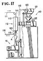
- Figures 16 and 17 show an injection molding machine 110 for injection-molding coupling elements on slide fastener tapes, the injection molding machine 110 being combined with the chopping apparatus 10 which is of substantially the same construction as described above.
- the injection molding machine 110 includes a mold assembly 112 composed of a movable mold 113 and a fixed mold. 114 for injection-molding coupling elements on slide fastener tapes 111 supplied between the molds 113, 114.
- the injection molding machine 110 also includes a supply hopper 121 for supplying new chips and a transfer cyclon 120 for supplying recycled chips. The new and recycled chips are fed from the supply hopper 121 and the transfer cyclon 120 into a mixing hopper 122, from which the chips are fed into a heating cylinder 123.
- the chips are then melted in the heating cylinder 123 and the melted synthetic resin material is injected into the mold assembly 112 to injection-mold coupling elements 126 (Figure 18) on the slide fastener tapes 111. Then, the movable mold 113 is moved away from the fixed mold 114, and a formed slide fastener stringer chain 116 is discharged from the mold assembly 112, and a runner structure A ( Figure 19) is separated from the stringer chain 116 by a separation roller pair 115. The runner structure A is then cut off and chopped by the chopping apparatus 10. Chopped chips discharged from the chopping apparatus 10 are delivered through a feed passage 119 into the transfer cyclon 120.
- the chopping apparatus 10 additionally includes a photoelectric tube 103 disposed between the separation roller pair 115 and the mold assembly 112 for detecting a sprue b as it passes by. A signal from the photoelectric tube 103 is used for actuating the air cylinder 34.
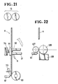
- the first cutter mechanism is arranged such that when the trailing end of the runner structure A leaves the roller pair 15, the sprue b is vertically positioned between the upper cutter 32 and the lower cutter 31.
- the vertical distance d 3 between the leading end of the runner structure A and the center of the feed roller 50 is substantially equal to the vertical distance d 4 between the cutter edge of the upper cutter 32 and the cutter edge of the lower cutter 31, the distance d 3 being preferably in the range of from 20 mm to 40 mm.
- the distance D between the center of the roller pair 15 and the center of the feed roller 50 is substantially equal to the length d 5 of the runner structure A plus the distance d 4 .
- the sprue b may be depressed the distance d 4 by the upper cutter 32 for positive downward delivery which is more reliable than gravity feed.
- Figure 21 shows the position of the parts in which the sprue b has just been severed from the runner a by the upper and lower cutters 32, 31.
- the runner structure A is not engaged simultaneously by the roller pair 15 and the feed roller 50. Where the sprue b is lowered by the upper cutter 32, the leading end of the runner a can reliably be fed into engagement with the feed roller 50. Therefore, the runner a can smoothly and quickly be fed along toward the feed roller 50.
- a bearing base 129 is disposed below a feed roller 128, and a roller 127 coacts with the feed roller 128forfeeding along the runner a.
- the cutter 51 is movable toward the bearing base 129 to chop the runner a on the bearing base 129.
Landscapes
- Engineering & Computer Science (AREA)
- Mechanical Engineering (AREA)
- Manufacturing & Machinery (AREA)
- Life Sciences & Earth Sciences (AREA)
- Forests & Forestry (AREA)
- Food Science & Technology (AREA)
- Slide Fasteners (AREA)
- Moulds For Moulding Plastics Or The Like (AREA)
- Processing And Handling Of Plastics And Other Materials For Molding In General (AREA)
- Separation, Recovery Or Treatment Of Waste Materials Containing Plastics (AREA)
- Injection Moulding Of Plastics Or The Like (AREA)
Claims (15)
Applications Claiming Priority (6)
| Application Number | Priority Date | Filing Date | Title |
|---|---|---|---|
| JP58166349A JPS6056522A (ja) | 1983-09-09 | 1983-09-09 | ランナ−切断方法及び装置 |
| JP166349/83 | 1983-09-09 | ||
| JP41011/84 | 1984-03-03 | ||
| JP4101184A JPS60186398A (ja) | 1984-03-03 | 1984-03-03 | ランナ−切断装置 |
| JP8842984A JPS60232920A (ja) | 1984-05-04 | 1984-05-04 | 合成樹脂製務歯を有するフアスナ−ストリンガ−を製造するランナ−切断装置付き射出成形機 |
| JP88429/84 | 1984-05-04 |
Publications (3)
| Publication Number | Publication Date |
|---|---|
| EP0144562A2 EP0144562A2 (fr) | 1985-06-19 |
| EP0144562A3 EP0144562A3 (en) | 1986-03-19 |
| EP0144562B1 true EP0144562B1 (fr) | 1989-12-20 |
Family
ID=27290677
Family Applications (1)
| Application Number | Title | Priority Date | Filing Date |
|---|---|---|---|
| EP19840110718 Expired EP0144562B1 (fr) | 1983-09-09 | 1984-09-07 | Procédé de et appareil pour tronçonner des carottes et seuils |
Country Status (12)
| Country | Link |
|---|---|
| US (1) | US4580963A (fr) |
| EP (1) | EP0144562B1 (fr) |
| KR (1) | KR860001404B1 (fr) |
| AU (1) | AU552900B2 (fr) |
| BR (1) | BR8404530A (fr) |
| CA (1) | CA1221346A (fr) |
| DE (1) | DE3480780D1 (fr) |
| ES (1) | ES8605180A1 (fr) |
| GB (1) | GB2146265B (fr) |
| HK (1) | HK22489A (fr) |
| MY (1) | MY101812A (fr) |
| SG (1) | SG81188G (fr) |
Families Citing this family (4)
| Publication number | Priority date | Publication date | Assignee | Title |
|---|---|---|---|---|
| AU551885B2 (en) * | 1983-11-15 | 1986-05-15 | Yoshida Kogyo K.K. | Recovery of scrap thermoplastics |
| JPH02280954A (ja) * | 1989-04-20 | 1990-11-16 | Yoshida Kogyo Kk <Ykk> | 連続射出成形方法とその装置 |
| US5090628A (en) * | 1990-02-06 | 1992-02-25 | Sierra Machinery, Inc. | Chip crusher |
| CN112388904B (zh) * | 2020-10-26 | 2022-05-31 | 凯视通机器人智能科技(苏州)有限公司 | 一种hud镜片全自动剪切机 |
Family Cites Families (9)
| Publication number | Priority date | Publication date | Assignee | Title |
|---|---|---|---|---|
| US2995775A (en) * | 1957-12-26 | 1961-08-15 | Richardson Co | Injection molding |
| US3418694A (en) * | 1966-09-30 | 1968-12-31 | Pennsalt Chemicals Corp | Apparatus scrap grinder and plastic injection molding machine |
| US3982632A (en) * | 1975-06-23 | 1976-09-28 | Owens-Illinois, Inc. | Thermoplastic injection runner transfer system |
| JPS6110964Y2 (fr) * | 1978-07-04 | 1986-04-08 | ||
| JPS6027608Y2 (ja) * | 1978-07-04 | 1985-08-21 | ワイケイケイ株式会社 | 連続スライドフアスナ−チエ−ン射出成形用金型 |
| US4321027A (en) * | 1979-06-18 | 1982-03-23 | Leesona Corporation | Under the press granulator construction |
| AU547902B2 (en) * | 1980-08-30 | 1985-11-14 | Yoshida Kogyo K.K. | Producing slide fasteners |
| JPS5991906A (ja) * | 1982-11-19 | 1984-05-26 | ワイケイケイ株式会社 | 合成樹脂製務歯を有するスライドフアスナ−チエンの製造装置 |
| JPS59101334A (ja) * | 1982-11-30 | 1984-06-11 | Yoshida Kogyo Kk <Ykk> | 合成樹脂製務歯を有するスライドフアスナ−チエンの製造装置 |
-
1984
- 1984-08-23 AU AU32314/84A patent/AU552900B2/en not_active Ceased
- 1984-08-24 GB GB8421608A patent/GB2146265B/en not_active Expired
- 1984-08-30 CA CA000462156A patent/CA1221346A/fr not_active Expired
- 1984-09-04 KR KR1019840005411A patent/KR860001404B1/ko not_active Expired
- 1984-09-06 BR BR8404530A patent/BR8404530A/pt not_active IP Right Cessation
- 1984-09-07 EP EP19840110718 patent/EP0144562B1/fr not_active Expired
- 1984-09-07 US US06/648,177 patent/US4580963A/en not_active Expired - Fee Related
- 1984-09-07 DE DE8484110718T patent/DE3480780D1/de not_active Expired - Lifetime
- 1984-09-10 ES ES84535784A patent/ES8605180A1/es not_active Expired
-
1987
- 1987-08-12 MY MYPI87001308A patent/MY101812A/en unknown
-
1988
- 1988-11-30 SG SG81188A patent/SG81188G/en unknown
-
1989
- 1989-03-16 HK HK224/89A patent/HK22489A/xx unknown
Also Published As
| Publication number | Publication date |
|---|---|
| KR850002413A (ko) | 1985-05-13 |
| AU552900B2 (en) | 1986-06-26 |
| GB8421608D0 (en) | 1984-09-26 |
| EP0144562A3 (en) | 1986-03-19 |
| GB2146265B (en) | 1987-01-14 |
| BR8404530A (pt) | 1985-08-06 |
| MY101812A (en) | 1992-01-31 |
| US4580963A (en) | 1986-04-08 |
| SG81188G (en) | 1989-04-21 |
| KR860001404B1 (ko) | 1986-09-23 |
| ES8605180A1 (es) | 1986-04-01 |
| CA1221346A (fr) | 1987-05-05 |
| DE3480780D1 (de) | 1990-01-25 |
| ES535784A0 (es) | 1986-04-01 |
| AU3231484A (en) | 1985-03-14 |
| HK22489A (en) | 1989-03-24 |
| EP0144562A2 (fr) | 1985-06-19 |
| GB2146265A (en) | 1985-04-17 |
Similar Documents
| Publication | Publication Date | Title |
|---|---|---|
| US4695418A (en) | Method and apparatus for manufacturing roof tiles and tiles made thereby | |
| CN114407235B (zh) | 一种塑料瓶高效分解回收机器人及其回收方法 | |
| CA2340552C (fr) | Amelioration de la methode et de l'appareil servant a reduire la taille des copeaux surdimensionnes | |
| CN109834744A (zh) | 一种青砖茶输送切割装置及方法 | |
| CN101450519A (zh) | 一种汽车传感器中金属嵌件塑料制品的生产方法 | |
| CN120985842A (zh) | 一种用于塑料汽车饰件生产的注射成型设备及工艺 | |
| US4580963A (en) | Method of and apparatus for chopping runners and sprues | |
| KR910006548B1 (ko) | 기다란 물품 연속 처리 장치 | |
| CN210501133U (zh) | 一种立式拉链注塑机的废料回收装置 | |
| US4160636A (en) | Injection molding apparatus for the manufacture of zippers | |
| CN213035164U (zh) | 注塑式树脂拉链用废料分离装置 | |
| US3651190A (en) | Manufacture of composite articles of moldable and nonmoldable materials | |
| JPH0148851B2 (fr) | ||
| EP0109662A1 (fr) | Dispositif pour la fabrication d'une chaîne continue de fermetures à glissière | |
| CN201753111U (zh) | 块状磁性材料制品自动装叠设备 | |
| EP0491874A1 (fr) | Appareil et methode pour la fabrication de tuiles | |
| JPH054981Y2 (fr) | ||
| CN113954164B (zh) | 一种扎带自动裁切装置和方法 | |
| CN119261082B (zh) | 一种注塑加工生产线 | |
| CN223057842U (zh) | 一种水口料自动切粒机 | |
| JPS601859Y2 (ja) | プレス装置 | |
| KR0128395Y1 (ko) | 김밥 자동 제조장치 | |
| CN210552892U (zh) | 一种薄膜挤出机的供料装置 | |
| US4040552A (en) | Stripping flash from blow moulded hollow containers | |
| KR100414993B1 (ko) | 슬라이드파스너의상지구와하지구를동시에성형하는장치 |
Legal Events
| Date | Code | Title | Description |
|---|---|---|---|
| PUAI | Public reference made under article 153(3) epc to a published international application that has entered the european phase |
Free format text: ORIGINAL CODE: 0009012 |
|
| AK | Designated contracting states |
Designated state(s): BE CH DE FR IT LI NL SE |
|
| PUAL | Search report despatched |
Free format text: ORIGINAL CODE: 0009013 |
|
| AK | Designated contracting states |
Kind code of ref document: A3 Designated state(s): BE CH DE FR IT LI NL SE |
|
| 17P | Request for examination filed |
Effective date: 19860618 |
|
| 17Q | First examination report despatched |
Effective date: 19871228 |
|
| GRAA | (expected) grant |
Free format text: ORIGINAL CODE: 0009210 |
|
| AK | Designated contracting states |
Kind code of ref document: B1 Designated state(s): BE CH DE FR IT LI NL SE |
|
| ET | Fr: translation filed | ||
| REF | Corresponds to: |
Ref document number: 3480780 Country of ref document: DE Date of ref document: 19900125 |
|
| ITF | It: translation for a ep patent filed | ||
| PLBE | No opposition filed within time limit |
Free format text: ORIGINAL CODE: 0009261 |
|
| STAA | Information on the status of an ep patent application or granted ep patent |
Free format text: STATUS: NO OPPOSITION FILED WITHIN TIME LIMIT |
|
| 26N | No opposition filed | ||
| ITTA | It: last paid annual fee | ||
| PGFP | Annual fee paid to national office [announced via postgrant information from national office to epo] |
Ref country code: NL Payment date: 19930930 Year of fee payment: 10 Ref country code: DE Payment date: 19930930 Year of fee payment: 10 |
|
| PGFP | Annual fee paid to national office [announced via postgrant information from national office to epo] |
Ref country code: SE Payment date: 19940608 Year of fee payment: 11 |
|
| PGFP | Annual fee paid to national office [announced via postgrant information from national office to epo] |
Ref country code: BE Payment date: 19940621 Year of fee payment: 11 |
|
| PGFP | Annual fee paid to national office [announced via postgrant information from national office to epo] |
Ref country code: FR Payment date: 19940818 Year of fee payment: 11 |
|
| PGFP | Annual fee paid to national office [announced via postgrant information from national office to epo] |
Ref country code: CH Payment date: 19940906 Year of fee payment: 11 |
|
| EAL | Se: european patent in force in sweden |
Ref document number: 84110718.8 |
|
| PG25 | Lapsed in a contracting state [announced via postgrant information from national office to epo] |
Ref country code: NL Effective date: 19950401 |
|
| NLV4 | Nl: lapsed or anulled due to non-payment of the annual fee | ||
| PG25 | Lapsed in a contracting state [announced via postgrant information from national office to epo] |
Ref country code: DE Effective date: 19950701 |
|
| PG25 | Lapsed in a contracting state [announced via postgrant information from national office to epo] |
Ref country code: SE Effective date: 19950908 |
|
| PG25 | Lapsed in a contracting state [announced via postgrant information from national office to epo] |
Ref country code: LI Effective date: 19950930 Ref country code: CH Effective date: 19950930 Ref country code: BE Effective date: 19950930 |
|
| BERE | Be: lapsed |
Owner name: YOSHIDA KOGYO K.K. Effective date: 19950930 |
|
| REG | Reference to a national code |
Ref country code: CH Ref legal event code: PL |
|
| PG25 | Lapsed in a contracting state [announced via postgrant information from national office to epo] |
Ref country code: FR Effective date: 19960531 |
|
| EUG | Se: european patent has lapsed |
Ref document number: 84110718.8 |
|
| REG | Reference to a national code |
Ref country code: FR Ref legal event code: ST |