EP0144938A2 - Fenêtre ou porte oscillo-battante - Google Patents
Fenêtre ou porte oscillo-battante Download PDFInfo
- Publication number
- EP0144938A2 EP0144938A2 EP84114585A EP84114585A EP0144938A2 EP 0144938 A2 EP0144938 A2 EP 0144938A2 EP 84114585 A EP84114585 A EP 84114585A EP 84114585 A EP84114585 A EP 84114585A EP 0144938 A2 EP0144938 A2 EP 0144938A2
- Authority
- EP
- European Patent Office
- Prior art keywords
- tilt
- actuator
- drive rod
- door according
- window
- Prior art date
- Legal status (The legal status is an assumption and is not a legal conclusion. Google has not performed a legal analysis and makes no representation as to the accuracy of the status listed.)
- Granted
Links
- 230000006835 compression Effects 0.000 claims description 7
- 238000007906 compression Methods 0.000 claims description 7
- 239000003380 propellant Substances 0.000 claims description 2
- 230000013011 mating Effects 0.000 claims 1
- 238000004519 manufacturing process Methods 0.000 description 5
- 230000008901 benefit Effects 0.000 description 4
- 230000036316 preload Effects 0.000 description 3
- 238000006073 displacement reaction Methods 0.000 description 2
- 238000003780 insertion Methods 0.000 description 2
- 230000037431 insertion Effects 0.000 description 2
- 238000009420 retrofitting Methods 0.000 description 2
- 230000008859 change Effects 0.000 description 1
- 238000010276 construction Methods 0.000 description 1
- 230000003993 interaction Effects 0.000 description 1
- 230000002035 prolonged effect Effects 0.000 description 1
- 230000004044 response Effects 0.000 description 1
- 230000000284 resting effect Effects 0.000 description 1
- 239000002023 wood Substances 0.000 description 1
Images

Classifications
-
- E—FIXED CONSTRUCTIONS
- E05—LOCKS; KEYS; WINDOW OR DOOR FITTINGS; SAFES
- E05D—HINGES OR SUSPENSION DEVICES FOR DOORS, WINDOWS OR WINGS
- E05D15/00—Suspension arrangements for wings
- E05D15/48—Suspension arrangements for wings allowing alternative movements
- E05D15/52—Suspension arrangements for wings allowing alternative movements for opening about a vertical as well as a horizontal axis
-
- E—FIXED CONSTRUCTIONS
- E05—LOCKS; KEYS; WINDOW OR DOOR FITTINGS; SAFES
- E05C—BOLTS OR FASTENING DEVICES FOR WINGS, SPECIALLY FOR DOORS OR WINDOWS
- E05C17/00—Devices for holding wings open; Devices for limiting opening of wings or for holding wings open by a movable member extending between frame and wing; Braking devices, stops or buffers, combined therewith
- E05C17/02—Devices for holding wings open; Devices for limiting opening of wings or for holding wings open by a movable member extending between frame and wing; Braking devices, stops or buffers, combined therewith by mechanical means
- E05C17/38—Devices for holding wings open; Devices for limiting opening of wings or for holding wings open by a movable member extending between frame and wing; Braking devices, stops or buffers, combined therewith by mechanical means with a curved rail rigid with the frame for engagement with means on the wing, or vice versa
-
- E—FIXED CONSTRUCTIONS
- E05—LOCKS; KEYS; WINDOW OR DOOR FITTINGS; SAFES
- E05Y—INDEXING SCHEME ASSOCIATED WITH SUBCLASSES E05D AND E05F, RELATING TO CONSTRUCTION ELEMENTS, ELECTRIC CONTROL, POWER SUPPLY, POWER SIGNAL OR TRANSMISSION, USER INTERFACES, MOUNTING OR COUPLING, DETAILS, ACCESSORIES, AUXILIARY OPERATIONS NOT OTHERWISE PROVIDED FOR, APPLICATION THEREOF
- E05Y2900/00—Application of doors, windows, wings or fittings thereof
- E05Y2900/10—Application of doors, windows, wings or fittings thereof for buildings or parts thereof
- E05Y2900/13—Type of wing
- E05Y2900/148—Windows
Definitions
- the invention relates to a tilt and turn window or door according to the preamble of claim 1.
- Such a tilt and turn window or door is known (DE-OS 31 11 579; DE-GM 77 07 617; DE-AS 12 57 036; DE-GM 75 26 548).
- the counter actuator is rigidly attached to the frame and the movable actuator is coupled to the drive rod means for common simultaneous movement, for example fixedly attached to a drive rod. If the drive rod means are now moved by appropriate actuation of the manual actuation means for the mutual engagement of the actuator and counteracting element in the functional position of the gap opening fixation in the corresponding actuation direction, but are subsequently moved in the same direction beyond this functional position, the actuator and counteracting element increasingly press in accordance with the force acting on the manual actuation means against each other with the risk of mutual damage.
- the functional position gap opening fixation often corresponds to an intermediate position (45 ° position), which can only be approached precisely with certain difficulties, especially by those who are used to the usual - tilt and turn fittings with only 90 0 adjustment angles.
- the actuator and counter-actuator there is no risk of mutual damage to the actuator and counter-actuator, if the operator precisely sets the intended gap opening position (predetermined tilt or rotation angle) of the wing, because when the Espagnolette means in the mentioned direction beyond the gap opening fixing position, the counter-actuator 9 only penetrates correspondingly deep into a slot 22 of the movable actuator 7, which slot is open on both sides.
- the wings during the movement of the drive rod means in the functional position stomatal fixierun q (for mutual engagement by actuator and Jacobstellqlied) is not qenau in which the pre-viewed gap opening position, also abuts the movable actuator butt against the counter actuator, with the risk mutual damage.
- the object of the invention is that the risk of damage to actuator and Ge g enstellglied if not properly operate the Drehkipp monos or decrease doorway of the type mentioned.
- the wing automatically assumes the closest gap opening position. Since the actuator and counter-actuator now engage in one another in a snap-in manner, the wing maintains this gap-opening position even when external forces, for example wind forces, act on it.
- the particularly preferred embodiment according to claims 6 and 7 is advantageous because the single element, namely the retaining rocker arm, both causes the movement of the actuator in dependence on the movement of the center rod and at the same time allows the spring-back movement of the actuator.
- the housing according to claim 9 allows the pre-assembly of the part comprising the movable actuator and the retaining device, which reduces the assembly costs in the manufacture of the tilt and turn window and also facilitates retrofitting.
- the housing is preferably constructed according to claim 10; It should be emphasized that only two parts have to be accommodated in the housing, namely the compression spring and the retaining rocker arm.
- the retaining rocker arm takes over the entire movement control of the movable actuator, thus ensures that when the drive rod means move, for example from the ready to rotate shaft position via the gap opening fixing position to the tilt ready position, the actuator is initially held back, then released (in the gap opening fixing position) and then withdrawn again.
- the reliability of the function is increased without a noticeable increase in the manufacturing outlay if two mutually independent cam control devices are provided.
- the control surface of the first cam control device now only needs to comprise a single step, for which purpose, for example, a corresponding slot for receiving the retaining rocker arm has to be incorporated in the drive rod with the particular advantage of a large adjustment path of the actuator, since the retaining rocker arm can dip into the slot. A possibly feared jamming of the rocker arm on the otherwise necessary second stage can no longer occur.
- the measures according to claim 12 ensure a particularly simple construction of the second cam control device.
- an insert according to claim 13 is proposed. This also makes retrofitting much easier, since now only the insert is to be inserted into a corresponding elongated hole in the drive rod means. This elongated hole can already be provided on the connecting rod means or can also be produced subsequently without any particular effort.
- the desired large tilt angle range is obtained due to the short distance to the tilt axis.
- the embodiment of the invention according to claim 16 offers the following advantage:
- the drive rod means When the drive rod means are shifted from the ready-to-tilt position towards the ready-to-turn position, the drive rod means usually move downwards in the lower half of the frame spar which is remote from the pivot bearing, that is to say in the direction. to the tilt axis.
- the movement reversal element now ensures that the movable actuator from the engagement position moves downward in the disengaged position when the drive rod means upwardly g from Spaltötechnischsfixierstellun be moved in the Kippkschaftsgna.
- the window frame spar which is remote from the axis of rotation, is thus clamped between the lower tilting bearing and the counter actuator in the mutually engaged position of the actuator and counter actuator in accordance with the spring preload.
- the sash thus reliably maintains the gap opening fixing position that is set.
- the actuator would engage the counteracting element from above, so that the sash frame may be adjusted, since this often only rests on a lower tilting bearing and, with the corresponding application of force or misalignment, for example a lower thrust bearing, may be over the teeth of the engagement comb of the actuator slides away.
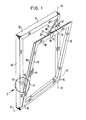
- a frame is generally designated 10 and a sash frame with 12.
- the sash frame is tiltable relative to the frame 10 about a tilt axis 14 and rotatable about an axis of rotation 16.
- An extension device 22 is arranged between the upper frame leg 18 and the upper casement leg 20, which includes an extension arm 24 and an additional link 28.
- the extension arm 24 is mounted on the frame 10 so as to be rotatable about the axis of rotation 16 and is connected at 26 to the upper casement leg 20 by a rotary slide guide.
- the additional arm 28 is articulated at 30 with the extension arm 24 and at 32 with the upper wing frame leg.
- a tilting bearing is provided which only functions for the purpose of tilting opening and can be opened for the purpose of rotating opening.
- the extension arm 24 is fixed on the sash frame 12 in a parallel position to the sash frame leg 20, namely in that a locking bar 38th of the casement 12 engages behind a locking bar 40 on the raising arm 24.
- the displacement of the locking bolt 28, the opening and closing of the tilting bearing 36 and the production of the engagement of further pairs of locking bolts, not shown, between the sash frame 12 and the frame 10 is effected by connecting rod means, which are moved along the respective sash frame arm by a manual actuation handle 44 on the sash frame arm remote from the axis of rotation will.
- An actuator 46 movable with the associated drive rod is attached to the sash frame leg 42, which is remote from the axis of rotation, and a counteracting element 50 fixed to the frame, which is remote from the axis of rotation.
- These actuators 46 and 50 act together to define several (in the example 7 shown) tilt-tilt positions of the sash.
- the tilt opening angle shown in FIG. 2 can be set in a wide range, for example in the range between 0 and 5 °, with a maximum tilt opening angle in the tilt ready position (without mutual engagement) of the actuators 46 and 50 according to FIG. 1 of, for example, 7 ° .
- a tilt opening angle range for the gap tilt positions up to and including the maximum tilt opening angle in the tilt-ready position of the fitting can also be achieved. Due to the proximity of the actuators 46 and 50 to the tilt axis 14, even with these relatively large tilt opening angles it is ensured that the actuators 46, 50 do not exceed the width indicated in FIG. 2 of the width a of the frame rebate circumferential surface of the sash frame 12 and the frame 10 . In a wide range of tilt opening angles, the tilt and tilt positions of the wing can thus be optionally set with the additional advantage that, in contrast to the tilt opening position of the wing in Fig. 1, the wing is secured in the respective gap tilt positions against slamming into the closed position.
- one of the two actuators namely the movable actuator 46
- the movable actuator 46 is designed to spring back in the direction away from the frame-fixed actuator 50, so that mutual damage to the counter actuators is prevented after incorrect operation of the fitting.
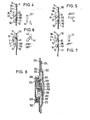
- the design of the actuators 46 and 50 is explained in more detail below with reference to FIGS. 2 and 3.
- a housing 52 holding the movable actuator 46 is screwed to a faceplate 56 by means of a slotted head screw 54;
- the housing 52 which is elongate in the direction of the faceplate 56, is provided with a projection 58 at both housing ends, the projection 58 closer to the tilt axis (lower in FIGS. 2 and 3) in a correspondingly adapted opening 60 of the faceplate 56 extends and the upper projection 58 into an elongated hole 62 of the faceplate 56.
- the housing 52 is formed in two parts with a bottom part 64 lying flat on the faceplate 56 and a cover part 66.
- the movable actuator 46 consists of a holder 76 which is elongated in the longitudinal direction of the faceplate and an engagement part 78 which can be fastened by means of a slotted head screw 80 at the upper end of the holder 76, either in the orientation shown in FIG. 2 for the right-hand stop, or in a position rotated by 180 ° about a vertical axis for left stop.
- the engagement part 78 has the shape of an engagement comb 81 with a total of 7 teeth 82 projecting upwards, which lie next to one another on an arc in a plane perpendicular to the window plane with the center of the circle lying on the tilt axis 14.
- the carrier 76 protrudes through an inlet opening 84 provided at the upper housing end into the housing interior 86 and its cross section is adapted to the housing cross-section, so that there is a linear guide of the carrier 76 in the longitudinal direction of the housing (double arrow B).
- a helical compression spring 88 in the housing interior 86 is supported on the one hand on the lower housing end wall 90 and on the other hand on the lower end of the carrier 76.
- a double arm lever 92 is mounted on the housing 52 with a tilt axis 94 which is perpendicular to the casement frame Provide bearing projections 96 which engage in a two common recess 98 of the faceplate 56. The intermediate double arm lever 92 consequently also passes through this recess 98.
- the two arms of the double arm lever 92 run away from one another.
- the left arm 100 in FIG. 3 engages in an elongated hole 102 of the carrier 76 parallel to the faceplate longitudinal direction within the housing 52.
- the end section of the carrier 76 in the form of a transverse web 104 adjoining the lower end of the elongated hole 102 is accordingly between the compression spring 88 and the Arm 100; when the double arm lever 92 is held, the web 104 is thus pressed against the arm 100 by the compression spring 88.
- the double arm lever 92 engages with its other arm 106 on the section 72 of the faceplate 74, depending on the respective drive rod position, it either engages in an elongated hole 108 of the faceplate (release position of the lever 92 according to FIGS.
- the double arm lever 92 together with the control surface (inner side 110 and slot 108) formed on the drive rod section 72, forms a first cam control device for controlling the movement of the movable actuator 46 as a function of the movement of the drive rod 74.
- a second cam control device which is independent of this is provided by the slotted-head screw 80 formed and a driving edge 114 of the drive rod 74.
- This driving edge 114 is formed by the upper end of an elongated hole 116 of the drive rod 74, which is cut in the region of the double offset at the upper end of section 72.
- the driving surface or driving edge 114 therefore lies in the same plane as the faceplate which adjoins section 72 upwards rail 56 immediately adjacent drive rod section 118.
- FIG. 8 Before going into the functional sequence with reference to FIGS. 4-7, the second embodiment according to FIG. 8 will be briefly explained. Components that correspond to those in FIGS. 2 and 3 are provided with the same reference numbers, each increased by the number 200.
- the difference between the two embodiments lies in the fact that instead of the section 72 which is to be shaped from the start on the drive rod, a separate insert 272 must now be inserted into a corresponding elongated hole 320 of the otherwise unchanged drive rod 274. This can already be done when the fitting is installed on the window or, if necessary, subsequently if the window is to be retrofitted to enable the gap opening positions.
- the insert 272 is provided with an elongated hole 308 corresponding in shape and position to the elongated hole 108, into which the double arm lever 292 is immersed in certain positions of the drive rod 274; otherwise the arm 306 rests on the outside 310 of the insert 272 following the elongated hole 308 downward under the pretension of the helical compression spring 288.
- the trim frame-fixed actuator 50 is equally suitable for the two configurations of the movable actuator, housing and drive rod in this area according to FIGS. 2 and 3 and FIG. 8. It consists of an L-angle piece of which one leg 400 on the inwardly facing frame rebate circumferential surface of the pivot bearing further frame legs 48, for example by means of two wood screws 402 (see FIGS. 2 and 3), and the other leg 404, which is parallel to the plane of the frame, is intended for engagement in the tooth space 406 between two successive teeth 82 of the movable actuator 46.
- the width b of the leg 404 perpendicular to the frame level therefore approximately corresponds to the clear tooth spacing.
- both the teeth 82 are pointed as well as the lower edge 405 of the leg 404 (bevel 408).
- the opposite upper edge 407 of the leg 404 is also provided with a bevel 408.
- the drive rod 74 is shown continuously according to FIGS. 2 and 3, with the cuff rail lying above it being omitted.
- the elongated hole 108 and the flat inner surface 110 of the drive rod 74 adjoining the elongated hole downward can be seen.
- the screw 80 connects the comb-shaped engagement part 78 to the holder 76, which is linearly displaceably mounted in the housing 52.
- Double arm lever 92 and, as indicated by dashed lines, the counter-actuator 50 which is fixed to the frame.
- FIG. 4 shows the "CLOSED" closed locking position of handle 44 and drive rod 74.
- actuator 46 In this position, actuator 46 is in its disengaged position, in which it is removed from counter-actuator 50.
- the actuator 46 assumes this position because the double arm lever 92 rests on the continuous outer side 110 of the section 72 and is therefore pivoted back counterclockwise into the position according to FIG. 8.
- the handle 44 is turned counterclockwise in FIG. Swiveled arrow direction C), this leads to a movement of the drive rod 74 downward (arrow D), since the drive rod section shown is below the gear, not shown, carrying the handle 44.
- FIG. 5 shows the handle 44 after a rotation in the specified sense by 90 ° into the “ready to turn” position in which the sash frame 12 can be turned around the axis 16.
- the actuator 46 is still in its Außerein g riffs- position corresponding to Fig. 8, since the slot 108 is still above the corresponding arm 106 of the double-92nd
- the engaging part 78 can therefore be easily pivoted past the counter-actuator 50 when the window is opened.
- the handle 44 If the handle 44 is now rotated further by approximately 45 ° in the same direction, it arrives in the gap opening fixing position designated by “SPALT-KIPP” in FIG. 6, in which the movable actuator 46 moves upward (arrow E) into the engagement position because the arm 106 of the double arm lever 92 in the Can pivot slot 108 (pivot direction F).
- this engagement position of FIG. 2 and 3 are the teeth 82 of the engagement ridge 81 in the same height as the lower edge 405 of the leg 404 of the Ge g enstell- member 50.
- the movable actuator 46 is again at a sufficient distance from the counter-actuator 50 so that the window can be tilted completely open.
- the actuator 46 can move into the engagement position according to FIGS. 2 and 3.
- This position is preferably not the g highest possible end position of the actuator 46 with a removed Ge enstell- member 50 is pressed so that even with mutual engagement of the actuator and counter actuator, the actuator 46 under spring tension against the counter actuator 50th This ensures mutual engagement even after prolonged use, for example when the casement 12 is lowered; furthermore, the actuator and counter-actuator do not have to be adjusted too precisely during assembly.
- the actuator 46 is resilient in the manner described and the teeth 82 are chamfered, a slight displacement of the actuator 46 is sufficient, whereupon the wing can be tilted into the desired gap opening position.
- the handle 44 is to be pivoted again clockwise into the 45 0 position according to FIG. 6.
Landscapes
- Engineering & Computer Science (AREA)
- Mechanical Engineering (AREA)
- Wing Frames And Configurations (AREA)
- Power-Operated Mechanisms For Wings (AREA)
- Window Of Vehicle (AREA)
- Closing And Opening Devices For Wings, And Checks For Wings (AREA)
Priority Applications (1)
| Application Number | Priority Date | Filing Date | Title |
|---|---|---|---|
| AT84114585T ATE33693T1 (de) | 1983-12-02 | 1984-11-30 | Drehkippfenster oder -tuer. |
Applications Claiming Priority (2)
| Application Number | Priority Date | Filing Date | Title |
|---|---|---|---|
| DE19833343755 DE3343755A1 (de) | 1983-12-02 | 1983-12-02 | Drehkippfenster oder -tuer |
| DE3343755 | 1983-12-02 |
Publications (4)
| Publication Number | Publication Date |
|---|---|
| EP0144938A2 true EP0144938A2 (fr) | 1985-06-19 |
| EP0144938A3 EP0144938A3 (en) | 1986-01-15 |
| EP0144938B1 EP0144938B1 (fr) | 1988-04-20 |
| EP0144938B2 EP0144938B2 (fr) | 1994-05-04 |
Family
ID=6215948
Family Applications (1)
| Application Number | Title | Priority Date | Filing Date |
|---|---|---|---|
| EP84114585A Expired - Lifetime EP0144938B2 (fr) | 1983-12-02 | 1984-11-30 | Fenêtre ou porte oscillo-battante |
Country Status (4)
| Country | Link |
|---|---|
| EP (1) | EP0144938B2 (fr) |
| JP (1) | JPH0730645B2 (fr) |
| AT (1) | ATE33693T1 (fr) |
| DE (2) | DE3343755A1 (fr) |
Families Citing this family (1)
| Publication number | Priority date | Publication date | Assignee | Title |
|---|---|---|---|---|
| DE29918458U1 (de) | 1999-10-19 | 2000-02-17 | AUBI Baubeschläge GmbH, 54411 Hermeskeil | Öffnungsbegrenzer |
Family Cites Families (7)
| Publication number | Priority date | Publication date | Assignee | Title |
|---|---|---|---|---|
| DE7416373U (de) * | 1974-10-10 | Rakoczy M | Arretierungsriegel für teilweise zu öffnende Kippfenster | |
| DE1584117A1 (de) * | 1965-01-27 | 1969-03-13 | Jaeger Kg Frank | Fluegelfeststeller fuer Fenster,Tueren od. dgl.,insbesondere fuer Kipp-Schwenkfluegel |
| DE7708222U1 (de) * | 1977-03-17 | 1977-06-30 | Siegenia-Frank Kg, 5900 Siegen | Spaltlueftungsvorrichtung fuer drehfluegelfenster |
| AT371201B (de) * | 1980-02-11 | 1983-06-10 | Siegenia Frank Kg | Feststellvorrichtung fuer fluegel von fenstern, tueren od.dgl. in wenigstens einer spaltlueftungsstellung |
| DE3022163C2 (de) * | 1980-06-13 | 1985-10-24 | Wilhelm Weidtmann Gmbh & Co Kg, 5620 Velbert | Dreh-Kipp-Beschlag für Fenster, Türen o.dgl. mit Spaltlüftung |
| DE3111579A1 (de) * | 1981-03-24 | 1982-10-14 | Fa. Aug. Winkhaus, 4404 Telgte | Drehkippfenster |
| AT371204B (de) * | 1981-07-10 | 1983-06-10 | Hrachowina Bauelemente Prod | Verschluss fuer dreh- und/oder kippfluegel |
-
1983
- 1983-12-02 DE DE19833343755 patent/DE3343755A1/de not_active Withdrawn
-
1984
- 1984-11-30 AT AT84114585T patent/ATE33693T1/de not_active IP Right Cessation
- 1984-11-30 EP EP84114585A patent/EP0144938B2/fr not_active Expired - Lifetime
- 1984-11-30 DE DE8484114585T patent/DE3470578D1/de not_active Expired
- 1984-12-03 JP JP59254269A patent/JPH0730645B2/ja not_active Expired - Lifetime
Also Published As
| Publication number | Publication date |
|---|---|
| EP0144938B1 (fr) | 1988-04-20 |
| JPH0730645B2 (ja) | 1995-04-10 |
| DE3470578D1 (en) | 1988-05-26 |
| EP0144938B2 (fr) | 1994-05-04 |
| ATE33693T1 (de) | 1988-05-15 |
| DE3343755A1 (de) | 1985-06-13 |
| EP0144938A3 (en) | 1986-01-15 |
| JPS60133175A (ja) | 1985-07-16 |
Similar Documents
| Publication | Publication Date | Title |
|---|---|---|
| DE69027893T2 (de) | Vorrichtung für die Schwenk-Kipp-Öffnung eines Fensters oder Türfensters | |
| DE2920581C3 (de) | Zusatzverriegelung, insbesondere Mittelverriegelung, für Fenster, Türen od.dgl. | |
| EP0119433B2 (fr) | Ferrure pour un panneau de fenêtre, de porte ou similaire, pouvant au moins basculer et se déplacer d'un plan dans un deuxième plan parallèle | |
| DE3738300A1 (de) | Fenster, tuer od. dgl. bei dem bzw. der zumindest der fluegelrahmen aus metall- oder kunststoffprofilen zusammengesetzt ist | |
| EP0422678B1 (fr) | Coffre à bagages | |
| DE68903724T2 (de) | Beschlag fuer tuer, fenster oder dergleichen. | |
| EP0440987B2 (fr) | Crémone | |
| EP0783616A1 (fr) | Fermeture a barre | |
| DE2813311C2 (fr) | ||
| DE2658626C3 (de) | Schaltsperre für Treibstangenbeschläge | |
| EP3183408B1 (fr) | Élément de commande pour système de ferrure | |
| DE69807608T2 (de) | Schliessvorrichtung, insbesondere Einsteckschloss mit einer Falle, für eine Fenstertür oder dergleichen | |
| EP3279418B1 (fr) | Élément de ferrure d'une ferrure et procédé de montage d'un tel élément de ferrure | |
| EP0144938B1 (fr) | Fenêtre ou porte oscillo-battante | |
| DE3221110C2 (fr) | ||
| DE2028695A1 (de) | Fehlbedienungssperre fur Drehkipp fenster oder türen | |
| EP4146888B1 (fr) | Ensemble charnière à actionnement commun | |
| EP1149974A1 (fr) | Dispositif de blocage | |
| DE69807801T2 (de) | Verriegelungsvorrichtung, insbesondere Einsteckschloss für den Flügel einer Tür oder eines Fensters | |
| EP0234213A2 (fr) | Tringle de commande | |
| AT509464B1 (de) | Schloss | |
| EP0683295B1 (fr) | Ferrure pour fenêtres, portes ou des choses pareilles oscillo-battantes | |
| DE2461228A1 (de) | Verschlussvorrichtung fuer fenster, tueren oder dergleichen | |
| DE1908478B2 (de) | Treibstangenverbindung | |
| DE69909879T2 (de) | Konstruktion für ein öffnungsfähiges Fahrzeugdach |
Legal Events
| Date | Code | Title | Description |
|---|---|---|---|
| PUAI | Public reference made under article 153(3) epc to a published international application that has entered the european phase |
Free format text: ORIGINAL CODE: 0009012 |
|
| AK | Designated contracting states |
Designated state(s): AT DE FR GB IT SE |
|
| RTI1 | Title (correction) | ||
| PUAL | Search report despatched |
Free format text: ORIGINAL CODE: 0009013 |
|
| AK | Designated contracting states |
Designated state(s): AT DE FR GB IT SE |
|
| 17P | Request for examination filed |
Effective date: 19860303 |
|
| 17Q | First examination report despatched |
Effective date: 19870701 |
|
| RAP1 | Party data changed (applicant data changed or rights of an application transferred) |
Owner name: AUG. WINKHAUS GMBH & CO. KG |
|
| GRAA | (expected) grant |
Free format text: ORIGINAL CODE: 0009210 |
|
| AK | Designated contracting states |
Kind code of ref document: B1 Designated state(s): AT DE FR GB IT SE |
|
| PG25 | Lapsed in a contracting state [announced via postgrant information from national office to epo] |
Ref country code: FR Effective date: 19880420 |
|
| REF | Corresponds to: |
Ref document number: 33693 Country of ref document: AT Date of ref document: 19880515 Kind code of ref document: T |
|
| ITF | It: translation for a ep patent filed | ||
| REF | Corresponds to: |
Ref document number: 3470578 Country of ref document: DE Date of ref document: 19880526 |
|
| GBT | Gb: translation of ep patent filed (gb section 77(6)(a)/1977) | ||
| EN | Fr: translation not filed | ||
| PLBI | Opposition filed |
Free format text: ORIGINAL CODE: 0009260 |
|
| PLBI | Opposition filed |
Free format text: ORIGINAL CODE: 0009260 |
|
| 26 | Opposition filed |
Opponent name: SIEGENIA-FRANK KG Effective date: 19881215 |
|
| 26 | Opposition filed |
Opponent name: WILH. FRANK GMBH Effective date: 19890116 Opponent name: SIEGENIA-FRANK KG Effective date: 19881215 |
|
| ITTA | It: last paid annual fee | ||
| PUAH | Patent maintained in amended form |
Free format text: ORIGINAL CODE: 0009272 |
|
| STAA | Information on the status of an ep patent application or granted ep patent |
Free format text: STATUS: PATENT MAINTAINED AS AMENDED |
|
| 27A | Patent maintained in amended form |
Effective date: 19940504 |
|
| AK | Designated contracting states |
Kind code of ref document: B2 Designated state(s): AT DE FR GB IT SE |
|
| GBTA | Gb: translation of amended ep patent filed (gb section 77(6)(b)/1977) |
Effective date: 19940601 |
|
| ITF | It: translation for a ep patent filed | ||
| EN3 | Fr: translation not filed ** decision concerning opposition | ||
| EAL | Se: european patent in force in sweden |
Ref document number: 84114585.7 |
|
| APAC | Appeal dossier modified |
Free format text: ORIGINAL CODE: EPIDOS NOAPO |
|
| APAC | Appeal dossier modified |
Free format text: ORIGINAL CODE: EPIDOS NOAPO |
|
| PGFP | Annual fee paid to national office [announced via postgrant information from national office to epo] |
Ref country code: GB Payment date: 20001024 Year of fee payment: 17 |
|
| PGFP | Annual fee paid to national office [announced via postgrant information from national office to epo] |
Ref country code: SE Payment date: 20001124 Year of fee payment: 17 |
|
| PG25 | Lapsed in a contracting state [announced via postgrant information from national office to epo] |
Ref country code: GB Free format text: LAPSE BECAUSE OF NON-PAYMENT OF DUE FEES Effective date: 20011130 |
|
| PG25 | Lapsed in a contracting state [announced via postgrant information from national office to epo] |
Ref country code: SE Free format text: LAPSE BECAUSE OF NON-PAYMENT OF DUE FEES Effective date: 20011201 |
|
| REG | Reference to a national code |
Ref country code: GB Ref legal event code: IF02 |
|
| GBPC | Gb: european patent ceased through non-payment of renewal fee |
Effective date: 20011130 |
|
| EUG | Se: european patent has lapsed |
Ref document number: 84114585.7 |
|
| PGFP | Annual fee paid to national office [announced via postgrant information from national office to epo] |
Ref country code: AT Payment date: 20021122 Year of fee payment: 19 |
|
| PGFP | Annual fee paid to national office [announced via postgrant information from national office to epo] |
Ref country code: DE Payment date: 20021128 Year of fee payment: 19 |
|
| PG25 | Lapsed in a contracting state [announced via postgrant information from national office to epo] |
Ref country code: AT Free format text: LAPSE BECAUSE OF NON-PAYMENT OF DUE FEES Effective date: 20031130 |
|
| PG25 | Lapsed in a contracting state [announced via postgrant information from national office to epo] |
Ref country code: DE Free format text: LAPSE BECAUSE OF NON-PAYMENT OF DUE FEES Effective date: 20040602 |
|
| APAH | Appeal reference modified |
Free format text: ORIGINAL CODE: EPIDOSCREFNO |