EP0145200A1 - Doppelseitige Aufnahmeplatte mit gespannter Oberfläche - Google Patents
Doppelseitige Aufnahmeplatte mit gespannter Oberfläche Download PDFInfo
- Publication number
- EP0145200A1 EP0145200A1 EP84307345A EP84307345A EP0145200A1 EP 0145200 A1 EP0145200 A1 EP 0145200A1 EP 84307345 A EP84307345 A EP 84307345A EP 84307345 A EP84307345 A EP 84307345A EP 0145200 A1 EP0145200 A1 EP 0145200A1
- Authority
- EP
- European Patent Office
- Prior art keywords
- support
- films
- disk
- main body
- stretched
- Prior art date
- Legal status (The legal status is an assumption and is not a legal conclusion. Google has not performed a legal analysis and makes no representation as to the accuracy of the status listed.)
- Withdrawn
Links
- 239000000463 material Substances 0.000 claims description 4
- 230000002093 peripheral effect Effects 0.000 claims 1
- JEIPFZHSYJVQDO-UHFFFAOYSA-N ferric oxide Chemical compound O=[Fe]O[Fe]=O JEIPFZHSYJVQDO-UHFFFAOYSA-N 0.000 abstract description 5
- 229960005191 ferric oxide Drugs 0.000 abstract description 5
- UQSXHKLRYXJYBZ-UHFFFAOYSA-N iron oxide Inorganic materials [Fe]=O UQSXHKLRYXJYBZ-UHFFFAOYSA-N 0.000 abstract description 5
- 235000013980 iron oxide Nutrition 0.000 abstract description 5
- 229920006254 polymer film Polymers 0.000 abstract description 2
- 239000010408 film Substances 0.000 description 97
- 238000003466 welding Methods 0.000 description 16
- 239000000853 adhesive Substances 0.000 description 6
- 230000001070 adhesive effect Effects 0.000 description 6
- 238000000034 method Methods 0.000 description 5
- 239000011800 void material Substances 0.000 description 5
- 239000011248 coating agent Substances 0.000 description 4
- 238000000576 coating method Methods 0.000 description 4
- 239000010409 thin film Substances 0.000 description 4
- 238000004519 manufacturing process Methods 0.000 description 3
- 238000002844 melting Methods 0.000 description 3
- 230000008018 melting Effects 0.000 description 3
- 239000002184 metal Substances 0.000 description 3
- 230000008569 process Effects 0.000 description 3
- 230000008901 benefit Effects 0.000 description 2
- 230000003247 decreasing effect Effects 0.000 description 2
- 230000000694 effects Effects 0.000 description 2
- 239000002861 polymer material Substances 0.000 description 2
- 239000007787 solid Substances 0.000 description 2
- 239000004698 Polyethylene Substances 0.000 description 1
- 230000007547 defect Effects 0.000 description 1
- 238000009826 distribution Methods 0.000 description 1
- 238000005516 engineering process Methods 0.000 description 1
- 238000001125 extrusion Methods 0.000 description 1
- 238000010438 heat treatment Methods 0.000 description 1
- 230000014759 maintenance of location Effects 0.000 description 1
- 239000000155 melt Substances 0.000 description 1
- 238000012986 modification Methods 0.000 description 1
- 230000004048 modification Effects 0.000 description 1
- 239000012768 molten material Substances 0.000 description 1
- 230000035515 penetration Effects 0.000 description 1
- 239000004033 plastic Substances 0.000 description 1
- 229920003023 plastic Polymers 0.000 description 1
- -1 polyethylene Polymers 0.000 description 1
- 229920000573 polyethylene Polymers 0.000 description 1
- 230000009467 reduction Effects 0.000 description 1
- 238000000926 separation method Methods 0.000 description 1
- 230000000007 visual effect Effects 0.000 description 1
- 238000004804 winding Methods 0.000 description 1
Images

Classifications
-
- G—PHYSICS
- G11—INFORMATION STORAGE
- G11B—INFORMATION STORAGE BASED ON RELATIVE MOVEMENT BETWEEN RECORD CARRIER AND TRANSDUCER
- G11B5/00—Recording by magnetisation or demagnetisation of a record carrier; Reproducing by magnetic means; Record carriers therefor
- G11B5/74—Record carriers characterised by the form, e.g. sheet shaped to wrap around a drum
- G11B5/82—Disk carriers
- G11B5/825—Disk carriers flexible discs
-
- G—PHYSICS
- G11—INFORMATION STORAGE
- G11B—INFORMATION STORAGE BASED ON RELATIVE MOVEMENT BETWEEN RECORD CARRIER AND TRANSDUCER
- G11B5/00—Recording by magnetisation or demagnetisation of a record carrier; Reproducing by magnetic means; Record carriers therefor
- G11B5/74—Record carriers characterised by the form, e.g. sheet shaped to wrap around a drum
- G11B5/82—Disk carriers
-
- G—PHYSICS
- G11—INFORMATION STORAGE
- G11B—INFORMATION STORAGE BASED ON RELATIVE MOVEMENT BETWEEN RECORD CARRIER AND TRANSDUCER
- G11B23/00—Record carriers not specific to the method of recording or reproducing; Accessories, e.g. containers, specially adapted for co-operation with the recording or reproducing apparatus ; Intermediate mediums; Apparatus or processes specially adapted for their manufacture
- G11B23/0014—Record carriers not specific to the method of recording or reproducing; Accessories, e.g. containers, specially adapted for co-operation with the recording or reproducing apparatus ; Intermediate mediums; Apparatus or processes specially adapted for their manufacture record carriers not specifically of filamentary or web form
- G11B23/0021—Record carriers not specific to the method of recording or reproducing; Accessories, e.g. containers, specially adapted for co-operation with the recording or reproducing apparatus ; Intermediate mediums; Apparatus or processes specially adapted for their manufacture record carriers not specifically of filamentary or web form discs
-
- G—PHYSICS
- G11—INFORMATION STORAGE
- G11B—INFORMATION STORAGE BASED ON RELATIVE MOVEMENT BETWEEN RECORD CARRIER AND TRANSDUCER
- G11B25/00—Apparatus characterised by the shape of record carrier employed but not specific to the method of recording or reproducing, e.g. dictating apparatus; Combinations of such apparatus
- G11B25/04—Apparatus characterised by the shape of record carrier employed but not specific to the method of recording or reproducing, e.g. dictating apparatus; Combinations of such apparatus using flat record carriers, e.g. disc, card
Definitions
- This invention relates generally to stretched surface recording disks which include a support structure and a thin film stretched in a plane parallel to the support body and attached to the periphery of the support.
- the invention relates to such a disk having two thin films stretched in planes parallel to the support and located on either side of the support.
- Stretched surface recording (SSR) disks generally consist of a rigid, circular support and a thin polymer film suitably attached to the periphery of the support.
- the film includes an iron-oxide outer coating which permits the disk to be utilized similar to linear magnetic tape to record and reproduce audio or visual signals.
- the disk configuration functions the same as the linear tape configuration in that audio or video signals are imparted to the magnetic, iron-oxide coating and reproduced from this coating by means of a transducer head as the iron-oxide coated medium is transported relative to the head.
- the disk configuration has greater utility than the tape configuration, however, because the entire information recorded on the disk is located in a single plane. This allows the transducer head to rapidly access widely separated portions of the recorded material, an advantage which is not possible with linear tape configurations.
- the present invention addresses many of foregoing problems by providing a double-sided SSR disk in which two film surfaces are stretched across opposite sides of a support structure and bonded to each other, rather than each being separately bonded to the support.
- the periphery of the support has a sharp edge located at the bonding junction of the two films which is engaged by either a bonding adhesive or molten film material produced during the film bonding process to lock the films in position relative to the support.
- the support further includes at least two planar reference surfaces axially spaced from the bond area which ensure that the films remain planar and bonding of the films to the structure does not interfere with the flatness of the films.
- a double-sided disk in which the recording films are bonded around the center of the support in addition to the periphery.
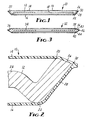
- FIGURE 1 illustrates in diametral cross-section a stretched surface recording (SSR) disk 10 which includes a support 12, an upper stretched film 14, and a lower stretched film 16.
- SSR disk 10 is adapted for use with electronic recording and reproducing equipment (not shown) in which the disk 10 is rotated and the outer surfaces of the films 14 and 16 are contacted by an electromagnetic transducer head which imparts signals to the films 14 or 16 or reproduces electronic signals from information previously imparted to the films 14 or 16.
- the stretched films 14 and 16 are provided on their outer surfaces with an iron-oxide coating as is well known in the audio and video tape arts.
- the equipment and electromagnetic transducer utilized in conjunction with the SSR disk 10 are similar to those presently utilized to record and reproduce audio or video signals with the exception that the recording medium is in the form of a circular disk rather than a longitudinal tape.
- the disk configuration is advantageous over the tape configuration in that all information contained on the recording medium (here the upper and lower films 14 and 16) is contained in a plane and thus widely separated portions of the information may be rapidly accessed by simply repositioning the transducer head rather than winding the tape with respect to the transducer.
- the support 12 may be manufactured of metal, plastic, or other suitable material and includes a central bore 18 which may be accessed by a spindle associated with the recording and reproduction equipment in order that the SSR disk 10 may be rotated.
- the films 14 and 16 are manufactured from a suitable polymer material, preferably polyethylene terapthalate, and each of the films 14 and 16 includes a central, circular cut-out portion 19 which permits access of the spindle to the support 12.
- the support 12 is provided, as best seen in FIGURE 2, with an upper reference surface 20 and a lower reference surface 22. These reference surfaces 20 and 22 are spaced above and below a planar main body portion 24 of the support 12 to define the furthermost axial extent of the support 12, and each provides an annular plane across which the films 14 and 16 may be stretched and removed from contact with the planar body portion 24 of the support 12.
- the support 12 In the radially outward direction from the upper reference surface 20, the support 12 includes a downwardly sloped surface 26, and from the lower reference surface 22, the support 12 includes an upwardly sloped surface 28. These sloped surfaces 26 and 28 meet at a point axially intermediate the reference surfaces 20 and 22 to form a sharp edge 30 which defines the furthermost radial extent of the disk 10 and at which the upper film 14 and the lower film 16 are bonded to each other.
- the edge 30 is a relatively sharp edge between the major surfaces 26 and 28 as it has a radius preferrably not greater than 0.005 inch.
- the films 14 and 16 may be adhesively or ultrasonically bonded to each other but are not necessarily bonded in any manner to the support 12 of the SSR disk 10. A direct bond between the support 12 and the films 14 and 16 may occur incidentally, but is not required for retention of the films 14 and 16.
- the sharp edge 30 is necessary to provide engagement between the films 14 and 16 and the support 12 to prevent any slippage or movement of the films 14 and 16 with respect to the support 12. At this point it should merely be recognized that the edge 30 is located below the reference surface 20 and above the reference surface 22 so that any separation of the films 14 or 16 with respect to the surfaces 26 or 28, or the edge 30, will not affect the flatness of the films 14 and 16-across the reference surfaces 20 and 22.
- FIGURE 3 illustrates a second embodiment of an SSR disk 32 according to the present invention which includes a support 34 which has a solid rim 36, which is triangular in cross-section, as opposed to the formed periphery of the support 12 of the SSR disk 10 of FIGURE 1.
- the solid rim 36 still includes raised reference surfaces 38 and 40 formed by the base angles of the triangular cross-section, inclined radially outwardly directed surfaces 42 and 44, and a sharp edge 46 at the intersection of the surfaces 42 and 44 which is located intermediate the reference surfaces 38 and 40.
- the features just described correspond in function to the respective features described with respect to the disk 10 of FIGURE 1 and illustrate that there are many workable configurations which may be assumed by the disk support 12 or 34.
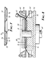
- FIGURE 4 illustrates schematically a fixture, generally indicated as 48, which may be utilized in the production of the SSR disk 10 or 32 of FIGURES 1 or 3.
- the fixture 48 includes a welding anvil 50, a base 52, a lower film clamp 54, an upper film clamp 56, a disk support clamp 58, an upper film tensioner 60 and a welding horn 62.
- the lower film 16 is first positioned across the anvil 50 and annularly clamped within the lower film clamp 54.
- the disk support 12 is then centered with respect to the fixture 48 and placed atop the lower film 16.
- Over the support 12 is stretched the upper film 14 which is held in position by the upper clamp 56.
- the upper film tensioner 60 is then lowered to deflect the film 14 to the anvil 50 and produce the desired tension in the upper film 14.
- the disk support clamp 58 is lowered to contact the upper film 14 and force the disk support 12 downwardly into contact with the anvil 50 through the lower film 16 and further tension the lower film 16.
- the welding horn 62 is lowered into pressure contact with the welding anvil 50, through the layers of film 14 and 16, and the base 52, and consequently the entire fixture 48, is rotated by means of a shaft 64.
- welding horn 62 may be revolved around the circumference of the clamp 58.
- FIGURES 5 and 6 Details of the welding process are illustrated by FIGURES 5 and 6 wherein FIGURE 5 depicts a partially welded condition and FIGURE 6 depicts a fully welded and completely bonded joint.
- FIGURE 5 illustrates that in the assembled, but not yet welded, configuration a void 66 exists between the lower film 16 and the edge 30. This void 66 cannot be permitted to remain in the completed product because such a space would allow movement of the upper film 14 and the attached lower film 16 relative to the edge 30 and consequently the reference surfaces 20 and 22. This movement would result in an altered, and possibly undesirable, distribution of tensioning stresses in the films 14 and 16 and movement of recorded information tracks with respect to the center of the SSR disk 10.
- the ultrasonic welding horn 62 is forced under pressure toward the welding anvil 50 through the upper and lower films 14 and 16.
- the result of this pressure is that when the polymer material of the films 14 and 16 melts, as indicated by the pool 68 shown in FIGURE 5, the molten material in the pool 68 is squeezed and extruded into the void 66.
- This extrusion completely fills and eliminates the void 66, as illustrated in FIGURE 6, and mechanically locks the upper and lower films 14 and 16 to the disk support 12 at the sharp corner 30. It is to be emphasized that no melting of the support 12 occurs and, therefore, there is no direct bonding between either of the films 14 and 16 and the support 12.
- the advantages of bonding the films 14 and 16 to each other rather than the disk support 12 are numerous. Since the support 12 need not be melted to form the bond, the support 12 can be manufactured of metal to provide increased stiffness and rigidity. The bond requires less area than prior methods because an extremely strong bond is formed between the two-films. The application of energy to the bond area need not be controlled as finely as is the case where it is attempted to weld a thin film to a relatively thick structure because the problem of sufficiently heating the thick structure without melting through the film is eliminated. In this regard it has been found that a heat-sinking effect of the metal anvil 50 and welding horn 62 prevents melting of the films throughout their thicknesses and greatly reduces or eliminates breakage of the film during welding. Finally, since the films are not bonded to the support, the films may be removed after assembly and the supports reused if defects appear in either of the films.
- the angle of the sharp edge 30 or 46 of the disk supports 12 or 34 has been shown in FIGURES 1 and 3, respectively, as being approximately 55 degrees. This angle is preferable because it have been found to produce optimum locking of the films 14 and 16 to their respective supports 12 and 34 while producing a maximum area of the films 14 and 16 which may be utilized to record information.
- a larger angle between the inclined surfaces 26 and 28 would appear to be desirable because then the edge 30 is moved inwardly toward the reference surfaces 20 and 22 and thus a greater percentage of the overall diameter of the disk 10 is usable for information recordation.
- the bond between the films 14 and 16 is more subject to failure because the forces tending to separate the films 14 and 16 acts more to peel one film from the other rather than shear the bond area.
- a bond between two films such as that shown is much more prone to failure in a "peel" mode than a shear mode.
- the likelihood of failure of the bond between the films 14 and 16 could be further decreased by extending the sharp edge 30 outwardly a greater distance from tiie reference surfaces 20 and 22 and thus decreasing the angle between the inclined surfaces 26 and 28.
- the bond would thus be more subject to shear than peel forces.
- extending the edge 30 outwardly would increase the radial distance between the reference surfaces 20 and 22 and the outer edge of the disk 10. This would decrease the percentage of the diameter of the disk 10 which is available for the recordation of information. For these reasons it has been found that it is desirable to maintain the angle of the edge 30 or 46 at about 55 degrees.
- FIGURE 7 illustrates a third embodiment of an SSR disk, generally indicated as 70, which includes an annular support 72 rather than the circular supports 12 and 34 described above.
- the SSR disk 70 allows an upper film 74 and a lower film 76 to be bonded to each other at the center of the disk 70 in addition to the periphery. Attachment of the films 74 and 76 to the center may be desirable to produce increased stiffness of the films 74 and 76 and thus reduced penetration of the transducer head relative to the plane of the films 74 and 76.
- the disk support 72 is provided at the outer edge with a structure 78 identical to that of FIGURES 1 and 2, and the films are bonded to each other in the manner described above.
- the film reference and attachment structure 80 located at the inner edge of the support 72 is likewise identical to the structure of FIGURES 1 a ⁇ d 2, and structure 78, with the exception that the attachment structure 80 at the inner edge of the disk support 72 is the mirror image of the structure 78 located at the outer edge of the support 72.
- the films 74 and 76 are bonded at the center of the disk 70 in a manner identical to the bonding of the films 74 and 76 at the periphery.
- FIGURE 7 depicts only reference and attachment structure 78 and 80 similar to that shown in FIGURES 1 and 2, it should be understood that the triangular rim 36 of FIGURE 3 could be provided at the inner and/or the outer edges of the disk support 72. It is simply required that the reference surfaces located to one side of the disk support be axially spaced an equal distance from the support to maintain the films parallel to the support in whatever combination of reference and attachment structures are used.
Landscapes
- Magnetic Record Carriers (AREA)
- Lining Or Joining Of Plastics Or The Like (AREA)
- Laminated Bodies (AREA)
- Packaging Of Annular Or Rod-Shaped Articles, Wearing Apparel, Cassettes, Or The Like (AREA)
Applications Claiming Priority (2)
| Application Number | Priority Date | Filing Date | Title |
|---|---|---|---|
| US54590983A | 1983-10-27 | 1983-10-27 | |
| US545909 | 1990-06-28 |
Publications (1)
| Publication Number | Publication Date |
|---|---|
| EP0145200A1 true EP0145200A1 (de) | 1985-06-19 |
Family
ID=24178022
Family Applications (1)
| Application Number | Title | Priority Date | Filing Date |
|---|---|---|---|
| EP84307345A Withdrawn EP0145200A1 (de) | 1983-10-27 | 1984-10-25 | Doppelseitige Aufnahmeplatte mit gespannter Oberfläche |
Country Status (6)
| Country | Link |
|---|---|
| EP (1) | EP0145200A1 (de) |
| JP (1) | JPS60115023A (de) |
| KR (1) | KR850003026A (de) |
| AU (1) | AU3321584A (de) |
| BR (1) | BR8405456A (de) |
| ZA (1) | ZA848386B (de) |
Cited By (4)
| Publication number | Priority date | Publication date | Assignee | Title |
|---|---|---|---|---|
| EP0186427A1 (de) * | 1984-12-21 | 1986-07-02 | Minnesota Mining And Manufacturing Company | Aufzeichnungsträger mit gespannter Oberfläche |
| US4835647A (en) * | 1984-12-21 | 1989-05-30 | Minnesota Mining And Manufacturing Company | Stretched surface recording medium |
| EP0283262A3 (en) * | 1987-03-20 | 1990-04-11 | Sony Corporation | Manufacturing magnetic recoding discs |
| US4963209A (en) * | 1984-12-21 | 1990-10-16 | Minnesota Mining And Manufacturing Company | Method for making stretched surface recording disk |
Families Citing this family (1)
| Publication number | Priority date | Publication date | Assignee | Title |
|---|---|---|---|---|
| US4952435A (en) * | 1985-10-03 | 1990-08-28 | Fuji Photo Film Co., Ltd. | Adhesive for a base-mounted flexible magnetic disc |
Citations (2)
| Publication number | Priority date | Publication date | Assignee | Title |
|---|---|---|---|---|
| FR2372488A1 (fr) * | 1976-11-25 | 1978-06-23 | Elektrotechnik Eisenach Kom | Disque d'enregistrement |
| EP0092325A1 (de) * | 1982-04-19 | 1983-10-26 | Minnesota Mining And Manufacturing Company | Aufnahmeplatte |
-
1984
- 1984-09-18 AU AU33215/84A patent/AU3321584A/en not_active Abandoned
- 1984-10-25 EP EP84307345A patent/EP0145200A1/de not_active Withdrawn
- 1984-10-26 KR KR1019840006663A patent/KR850003026A/ko not_active Withdrawn
- 1984-10-26 ZA ZA848386A patent/ZA848386B/xx unknown
- 1984-10-26 JP JP59224308A patent/JPS60115023A/ja active Pending
- 1984-10-26 BR BR8405456A patent/BR8405456A/pt unknown
Patent Citations (2)
| Publication number | Priority date | Publication date | Assignee | Title |
|---|---|---|---|---|
| FR2372488A1 (fr) * | 1976-11-25 | 1978-06-23 | Elektrotechnik Eisenach Kom | Disque d'enregistrement |
| EP0092325A1 (de) * | 1982-04-19 | 1983-10-26 | Minnesota Mining And Manufacturing Company | Aufnahmeplatte |
Non-Patent Citations (1)
| Title |
|---|
| PATENT ABSTRACTS OF JAPAN vol. 6, no. 162, 25th August 1982, page (P-137) (1040); & JP-A-57-78634 (MATSUSHITA) 17-05-1982 * |
Cited By (4)
| Publication number | Priority date | Publication date | Assignee | Title |
|---|---|---|---|---|
| EP0186427A1 (de) * | 1984-12-21 | 1986-07-02 | Minnesota Mining And Manufacturing Company | Aufzeichnungsträger mit gespannter Oberfläche |
| US4835647A (en) * | 1984-12-21 | 1989-05-30 | Minnesota Mining And Manufacturing Company | Stretched surface recording medium |
| US4963209A (en) * | 1984-12-21 | 1990-10-16 | Minnesota Mining And Manufacturing Company | Method for making stretched surface recording disk |
| EP0283262A3 (en) * | 1987-03-20 | 1990-04-11 | Sony Corporation | Manufacturing magnetic recoding discs |
Also Published As
| Publication number | Publication date |
|---|---|
| AU3321584A (en) | 1985-05-02 |
| KR850003026A (ko) | 1985-05-28 |
| ZA848386B (en) | 1986-06-25 |
| JPS60115023A (ja) | 1985-06-21 |
| BR8405456A (pt) | 1985-09-03 |
Similar Documents
| Publication | Publication Date | Title |
|---|---|---|
| US4670072A (en) | Method of making a stretched surface recording disk | |
| EP0107421B1 (de) | Scheibenförmiger Aufzeichnungsträger mit gespannter Oberfläche und Verfahren zur Herstellung | |
| US6347070B1 (en) | Plastic clamp with hub and platter for use in disc drive | |
| US4562505A (en) | Flexible magnetic memory disk with metallic hub and method of manufacturing same | |
| JPH0454606Y2 (de) | ||
| JPS60115023A (ja) | 二重側面の伸張面録音デイスク | |
| JP2000173229A (ja) | テープリール | |
| CN1030995A (zh) | 制造信息记录盘的方法 | |
| JPH0576102B2 (de) | ||
| JPS6396755A (ja) | 光学式情報記録円盤の製造方法 | |
| EP0092325B1 (de) | Aufnahmeplatte | |
| US4897134A (en) | Ultrasonic welding hubs to magnetic recording diskettes | |
| CA1305791C (en) | Method for manufacturing a magnetic recording disk | |
| JPH0576898B2 (de) | ||
| JP2876542B2 (ja) | フレキシブル磁気ディスク | |
| JPS63153776A (ja) | 情報デイスク | |
| JPS6386172A (ja) | 磁気記録装置 | |
| JPS60133567A (ja) | 円盤状記録媒体の支持装置 | |
| JPS61115286A (ja) | デイスクカ−トリツジ | |
| JPS60103537A (ja) | 情報記録媒体の製造方法 | |
| JPS60173741A (ja) | 情報記録基板の製造方法 | |
| JPH03230381A (ja) | 光情報記録媒体用基板 | |
| JPH0452809Y2 (de) | ||
| JPH05314473A (ja) | 記録ディスクの製造方法 | |
| JP3181558B2 (ja) | 光情報記録媒体 |
Legal Events
| Date | Code | Title | Description |
|---|---|---|---|
| PUAI | Public reference made under article 153(3) epc to a published international application that has entered the european phase |
Free format text: ORIGINAL CODE: 0009012 |
|
| AK | Designated contracting states |
Designated state(s): DE FR GB IT |
|
| 17P | Request for examination filed |
Effective date: 19851118 |
|
| 17Q | First examination report despatched |
Effective date: 19870119 |
|
| STAA | Information on the status of an ep patent application or granted ep patent |
Free format text: STATUS: THE APPLICATION IS DEEMED TO BE WITHDRAWN |
|
| 18D | Application deemed to be withdrawn |
Effective date: 19870730 |
|
| RIN1 | Information on inventor provided before grant (corrected) |
Inventor name: SKOW, LYNN R.C/O MINNESOTA MINING AND Inventor name: LOUKS, JOHN W.C/O MINNESOTA MINING AND |