EP0145277A1 - Elimination des signaux parasites en résonance magnétique nucléaire - Google Patents
Elimination des signaux parasites en résonance magnétique nucléaire Download PDFInfo
- Publication number
- EP0145277A1 EP0145277A1 EP84307728A EP84307728A EP0145277A1 EP 0145277 A1 EP0145277 A1 EP 0145277A1 EP 84307728 A EP84307728 A EP 84307728A EP 84307728 A EP84307728 A EP 84307728A EP 0145277 A1 EP0145277 A1 EP 0145277A1
- Authority
- EP
- European Patent Office
- Prior art keywords
- pulse
- signals
- phase
- line
- sequence
- Prior art date
- Legal status (The legal status is an assumption and is not a legal conclusion. Google has not performed a legal analysis and makes no representation as to the accuracy of the status listed.)
- Granted
Links
- 238000005481 NMR spectroscopy Methods 0.000 title claims description 50
- 230000005284 excitation Effects 0.000 claims abstract description 36
- 230000009466 transformation Effects 0.000 claims abstract description 26
- 238000003384 imaging method Methods 0.000 claims abstract description 12
- 238000000034 method Methods 0.000 claims description 20
- 238000001208 nuclear magnetic resonance pulse sequence Methods 0.000 claims description 15
- 230000000694 effects Effects 0.000 claims description 10
- 230000004044 response Effects 0.000 claims description 6
- 238000013421 nuclear magnetic resonance imaging Methods 0.000 claims 9
- 238000013480 data collection Methods 0.000 claims 4
- 230000004075 alteration Effects 0.000 claims 1
- 230000001747 exhibiting effect Effects 0.000 claims 1
- 238000005070 sampling Methods 0.000 description 17
- 230000006698 induction Effects 0.000 description 15
- 239000000463 material Substances 0.000 description 9
- 230000008569 process Effects 0.000 description 5
- 230000005415 magnetization Effects 0.000 description 4
- 230000003595 spectral effect Effects 0.000 description 3
- 238000013459 approach Methods 0.000 description 2
- 230000005540 biological transmission Effects 0.000 description 2
- 230000001427 coherent effect Effects 0.000 description 2
- 238000010586 diagram Methods 0.000 description 2
- 238000002592 echocardiography Methods 0.000 description 2
- 238000001228 spectrum Methods 0.000 description 2
- 230000003068 static effect Effects 0.000 description 2
- 238000005084 2D-nuclear magnetic resonance Methods 0.000 description 1
- 238000002097 J-spectroscopy Methods 0.000 description 1
- 230000002411 adverse Effects 0.000 description 1
- 230000001413 cellular effect Effects 0.000 description 1
- 230000000052 comparative effect Effects 0.000 description 1
- 230000008878 coupling Effects 0.000 description 1
- 238000010168 coupling process Methods 0.000 description 1
- 238000005859 coupling reaction Methods 0.000 description 1
- 238000001514 detection method Methods 0.000 description 1
- 230000003292 diminished effect Effects 0.000 description 1
- 230000008030 elimination Effects 0.000 description 1
- 238000003379 elimination reaction Methods 0.000 description 1
- 238000002474 experimental method Methods 0.000 description 1
- 230000002349 favourable effect Effects 0.000 description 1
- 239000011159 matrix material Substances 0.000 description 1
- 230000009467 reduction Effects 0.000 description 1
- 230000002787 reinforcement Effects 0.000 description 1
- 238000000926 separation method Methods 0.000 description 1
- 230000001629 suppression Effects 0.000 description 1
- 238000000293 three-dimensional nuclear magnetic resonance spectroscopy Methods 0.000 description 1
Images


Classifications
-
- G—PHYSICS
- G01—MEASURING; TESTING
- G01R—MEASURING ELECTRIC VARIABLES; MEASURING MAGNETIC VARIABLES
- G01R33/00—Arrangements or instruments for measuring magnetic variables
- G01R33/20—Arrangements or instruments for measuring magnetic variables involving magnetic resonance
- G01R33/44—Arrangements or instruments for measuring magnetic variables involving magnetic resonance using nuclear magnetic resonance [NMR]
- G01R33/48—NMR imaging systems
- G01R33/54—Signal processing systems, e.g. using pulse sequences ; Generation or control of pulse sequences; Operator console
- G01R33/56—Image enhancement or correction, e.g. subtraction or averaging techniques, e.g. improvement of signal-to-noise ratio and resolution
- G01R33/565—Correction of image distortions, e.g. due to magnetic field inhomogeneities
Definitions
- This invention relates to techniques for removing unwanted artifact signal components from nuclear magnetic resonance (NM R ) signals and, in particular, to techniques for artifact removal in NMR imaging systems through control of the phase relationships of radio frequency (r.f.) pulses in an NMR excitation sequence prior to Fourier transformation.
- NM R nuclear magnetic resonance
- the NM R technique may be used to form images of several characteristics of cellular and other materials.
- the object to be imaged is placed in a static magnetic field, whereby atomic nuclei align themselves with the static field. This field is disturbed in a controlled manner by excitation signals from a radio frequency coil, disturbing the nuclei from their equilibrium alignment. When the disturbing signals are removed, the nuclei begin to assume their original alignment, and emit energy in the process.
- the emitted signals are detected by the transmitting r.f. coil, or by another dedicated receiving r.f. coil.
- the signals are spatially encoded with magnetic field gradients.
- the detected signals are then processed to produce an image, typically of a plane or planes of the object being imaged.
- detected NMR signals should contain only specific information relating to the characteristics of the material being imaged, uncontaminated by spurious signal components. Numerous efforts have been directed toward this goal. For instance, in the case of one dimensional pulse-Fourier transform NMR signals, an unwanted steady- state-free-precession type of refocussing can build up at the end of a desired free induction decay experiment. One approach toward eliminating this build-up is variation of the interpulse delay between excitation pulses.
- a second technique for improving resolution is to increase the time window during which the NMR signal is sampled. By gathering more information in the time domain, a greater spectral resolution is available for Fourier transform processing, resulting in greater spectral resolution in the spatial representation of the NMR signals.
- NMR signals In the time domain, two types of NMR signals can be produced. One type is the free induction signal-, an r.f. signal emitted immediately following a single r.f. excitation pulse.
- the second type of NMR signal is the multiple pulse response, of which the spin-echo signal is an example.
- Spin-echo signals may be induced, for instance, by tipping the bulk magnetization to the (x-y) plane with a 90° excitation pulse. Following the 90° pulse, a second, 180° pulse is applied, and the components of magnetization begin to refocus in the (x-y) plane and regain phase coherence momentarily. As they rephase, a spin-echo signal is developed. The emitted spin-echo signal resembles back-to-back free induction signals, with a signal peak occurring after the second r.f. pulse at a time equal to the time separation of the two r.f. pulses.
- the sampling window for the spin echo signal may be adjusted in both directions (in time) relative to the signal peak.
- free induction signal components generated from each of the two pulses individually, but primarily the second r.f. pulse are also present.
- These unwanted components are caused by r.f. magnetic field inhomogeneities, or by tip angle missettings.
- a perfect 180° pulse causes no free induction decay signal; however, it is not always possible to generate a perfect pulse.
- phase of the second excitation pulse, the phase of the receiver reference signal, or preferably both are alternated over a number of different data acquisitions.
- the data recovered from the different acquisitions, preferably four in number, is summed, resulting in coherent addition of spin-echoes and phase cancellation of artifacts.
- the foregoing technique requires that as many as four excitation pulse sequences of two pulses each be performed in order to provide for proper constructive reinforcement and cancellation.
- the time required to perform four sequences may be insubstantial for scans of small areas, but the aggregate time allocation may be significant when performing scans of large areas or three dimensions. This is due to the physical principles inherent in NMR imaging.
- time must be allotted for the disturbed spin system to relax.
- the allocated time for relaxation is governed by the immutable spin-spin and spin-lattice relaxation time constants.
- this NMR spectroscopy technique for artifact cancellation would impose a severe time constraint in NMR imaging.
- a technique for eliminating artifacts in NMR imaging during image reconstruction from a single data acquisition.
- Lines within a data set are scanned, with the phase of an excitation pulse or the phase of the receiver reference signal or both alternated from line to line.
- the time domain signal information is then processed by Fourier transformation.
- the imposition of the proper phase of the excitation pulses or reference signals provides the artifact components with a rapid phase alternative which, in the process of Fourier transformation, results in their reconstruction at the edge of the image.
- the artifacts are thus located away from the center of the image, which is generally the image area of greatest interest.
- the artifact components are made to alternate phase coherently by alternation of the phase of a r.f. excitation signal.
- the desired spin-echo signals possess no such alternation.
- a two-or three-dimensional Fourier transformation is then performed with respect to the direction of this alternation, resulting in the reconstruction of the phase coherent artifact components at the edge of the image.
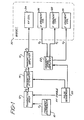
- a transmitter mixer 12 receives a signal F s , where F s is the transmitted radio frequency NMR signal, from a frequency synthesizer 10.
- the F s signal is heterodyned by the mixer to prod-ace the F s signal, which is coupled by way of a controlled transmitter attenuator 14 to a transmitter amplifier 16.
- the transmitter mixer 12 and attenuator 14 are controlled by control signals provided by a pulse sequencer 20, which applies an r.f. enable signal to the mixer 12.
- the F s signal is amplified by the amplifier 16 and applied to the r.f. coil 24 in the magnet 30 in the form of a sequence of pulses formed under control of the pulse sequencer 20.
- the r.f. coil 24 applies the F s pulses to the subject being imaged.
- x, y, and z gradient coils 26, 28, and 29 are also located within the field of the magnet 30. These coils receive gradient control signals G x , Gy, and G z from gradient signal amplifiers 22. The control signals are produced by the pulse sequencer 20.
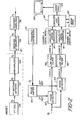
- the NMR signals emitted by the nuclei of the material being imaged induce F s return signals in the r.f. coil 24. These return signals are coupled by way of an r.f. matching network 27 to a pre-amplifier 29 , and on to a receiver attenuator 34 as shown in FIGURE 2.
- the received F s signals are amplified by an amplifier 36 and applied to quadrature phase detectors 42 and 44.
- the phase detectors receive two phase demodulating signals at respective 0° and 90° phase angles from a phase shifter 40, which receives an F s reference signal from the frequency synthesizer 10.
- the phase detectors 42 and 44 produce a channel A and a channel B signal, respectively.
- the baseband A and B signals are filtered by respective low pass filters 46 and 48, and the filtered signals are then sampled by respective analog to digital converters 50 and 52.
- the resultant channel A and channel B digital words are stored in a the memory of a computer 60.
- the channel A and B digital words are then combined and transformed to the frequency domain by a Fourier transform array processor 62.
- the resultant image signals are assembled in an image format by an image processor 64, and the processed image is displayed on a video monitor 66.
- the scan line there shown includes the two pulse sequence of a 90 degree pulse 70 and a 180 degree pulse 72.
- Free decay signals 71 and 73 follow the respective excitation pulses, and the desired spin-echo signal 75 is shown occurring during a sampling period T s .
- gradient coils 26, 28 and 29 of FIGURE 1 are energized by gradient pulses G x , Gy and G z as shown in FIGURE 3.
- the G x gradient pulse is applied following the 90 degree excitation pulse and during the time of acquisition of the spin-echo signal 75.
- the G z gradient pulse is applied during the first excitation pulse period to spatially identify the (x-y) plane which is to be imaged.
- the Gy gradient pulse is applied during the interval between the two excitation pulses to impose a spatially encoded phase factor onto the signal.
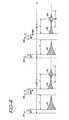
- each two pulse sequence is comprised of an a° pulse and a following ⁇ ° pulse, after which a spin echo signal is generated by the nuclei and detected by the r.f. coil.
- the a° pulse is a 90 degree pulse and the ⁇ ° pulse is a 180 degree pulse as shown in the scanning sequences of FIGURE 4.
- a 90 degree pulse 70 is transmitted followed by a -relaxation period ⁇ .
- a free induction signal 71 is produced by the material being imaged, a signal which is not read by the receiver circuitry.
- a 180 degree pulse 72 is transmitted which exhibits a phase ⁇ .
- the 180 degree pulse should cause the bulk magnetization of the material being imaged to refocus in a direction opposite to that in which it was first "tipped" in the transverse (x-y) plane.
- an additional free decay signal 73 develops immediately following the end of the 180 degree pulse 72.
- the signal 73 rapidly decays, and is succeeded by the desired spin echo signal 75 as the bulk magnetization refocuses in the (x-y) plane.
- the spin-echo signal 75 peaks around a time T following the 180 degree pulse, and is detected and sampled during sampling period T s .
- the present inventors have found that favorable signal-to-noise conditions are attained by setting the sampling period duration T s at least equal to the time T , and setting T equal to T 2/ 4 for the T 2 relaxation characteristic of the material being imaged.
- the sampling period Tp is centered in time around the time of occurrance of the spin-echo signal peak.
- a second scanning sequence for line n+1 is performed.
- the line n+1 sequence differs from the line n sequence in that the 180 degree pulse 82 exhibits a phase of 0 + 180°, in phase opposition to that of the preceding 180 degree pulse 72.
- the generated spin-echo signal 85 is detected and sampled during the Ts sampling period of the line n+1 sequence.
- the desired spin-echo signal is unaffected by the different phasing of the 180 degree pulse 82.
- the unwanted free induction decay signal 83 has been phase-shifted by 180 degrees in comparison to the previous free induction decay signal 73.
- the detected spin-echo signals over a plurality of scan lines are sampled by the analog to digital converters 50 and 52 in FIGURE 2, which produces signal information in the form of discrete digital words.
- These digital words, A and B are arranged in a matrix array of complex numbers of the form Aj(t) + iBj(t), where t references the time of sampling during the sampling interval T s , and j refers to line numbers.
- -A Fourier transformation is then performed to convert the time domain data to a spatially representative frequency domain using Fourier transformation.
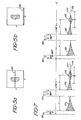
- the result of the alternate phasing of the 180 degree pulses 72 and 82 is to alternately phase encode the artifact signals 73 and 83. Without this phase encoding, the portions of the artifact signals occurring during the sample time T s would have no phase modulation, as they are induced at a time when there is no Gy pulse. In the process of Fourier transformation the randomly phased artifacts would manifest themselves as a distribution of signals about the zero frequency value in the center of the image in the y-direction, as indicated by the artifacts 90 in FIGURE 5a.
- the artifacts will manifest themselves as components located in the frequency spectrum at the limit of that employed in the Fourier transformation process, which causes them to appear at the edge of the image as shown by artifacts 92 in FIGURE 5b.
- the artifacts are thus removed from the center of the image, which is generally the region of primary interest.
- FIGURE 6 depicts a plane of raw data before Fourier transformation.
- the spin-echo signals for the various lines of data are shown as a group of generally harmonically related waveforms 100, each having a center along the time axis at t c .
- the undesired free decay artifact signals 102 At the left hand side of the time axis and along the edge of the Gy axis are the undesired free decay artifact signals 102. It is seen that, from line to line, the phasing of the artifact signals alternates at the same respective time location on each line.
- the phase alternation at the line rate encodes the artifacts by this frequency dependence, resulting in the appearance of the artifacts at the boundary of the Fourier transformed image plane.
- the artifacts are thereby removed from the center and other disadvantageous locations in the final image.
- FIGURE 7 is similar to FIGURE 4, in that it shows two lines of image data acquisition using two-pulse sequences.
- the first line n includes a 90 degree pulse 170 which exhibits a phase ⁇ , followed by a 18 0 degree pulse 172.
- Free induction decay signals 171 and 173 are developed following each excitation pulse, and a spin-echo signal 175 is developed at time after the 180 degree pulse 172.
- the second line n+l in FIGURE 7 includes a 90 degree pulse 180 which exhibits a phase ⁇ +180°.
- the 90 degree pulse 180 is followed by a 180 degree pulse 182.
- Free induction decay signals 181 and 183 are developed after each excitation pulse, and a spin-echo signal 185 is produced at time T after the 180 degree pulse 182.
- the alternate phasing of the 90 degree pulses from line to line phase modulates the unwanted free induction decay signals 173 and 183 and the spin-echo signals 175 and 185 in the following manner.
- the unwanted signals 173 and 183 are in phase at respective points in time following the 180 degree pulses from line to line.
- the spin-echo signals 175 and 185 are in respective phase opposition from line to line as shown in the FIGURE.
- the reference phase of the receiver is alternated from line to line. This may be done electronically, for instance, by shifting the reference phase applied to phase detector 42 and 44 in FIGURE 2 from line to line.
- phase detectors 42 and 44 receive 0° and 90° phase reference signals, and during line n+l the phase detectors receive 180° and 270° phase reference signals.
- This phase alternation brings the spin-echo signals back into the same phase relationship during the sampling periods T s , and also shifts the unwanted free induction decay signals into phase opposition from line to line.
- the signals are then sampled during the T s sampling periods, and the resulting data sets are subjected to Fourier transformation.
- the Fourier transformation of the phase modulated artifact signals cause them to appear at the edge of the image, since their spectral location is at the limit of that employed in the Fourier transformation process.
- the present inventors have found that it is preferential not to switch the phases of the phase detector reference signals, but to sample the signals and perform the phase shifting through software manipulation of the sampled data values in the computer 60.
- the software phase shifting is perfomed prior to Fourier transformation with the same result, and without the electronic complexity of electronic reference signal switching.
- This technique of alternating the phase of the a (90 degree) pulse from line to line also results in the elimination of D .C. signal offsets.
- the dashed lines 177 in FIGURE 7 indicate the true center line of the received signals.
- the effects of signal coupling and biasing in the receiver electronics may cause the true center line of the signals to be offset from the D.C. reference level 179 by the time the signals are digitized.
- this technique of artifact removal also causes the undesired D.C. offset to be modulated from line to line and appear at the edge of the image, provided that the offset is substantially constant during acquisition of the image.
- FIGURE 8 shows line n and line n+1 signal waveforms referenced to a common sampling period Ts .
- the dots on the waveform indicate sampling times.
- the upper waveform is comprised of artifact signal 173 most visible during time segment t ART , and spin-echo signal 175 during time segment t SE .
- the two signal segments are shown as being monotonal, although it is recognized that in an actual embodiment the signal during time segment t ART will be a complex waveform of both the spin-echo and artifact signals.
- the lower waveform comprised of artifact signal 183' and spin-echo signal 185' is shown inverted relative to waveforms 183 and 185 in FIGURE 7; however, the illustrated effect is the same as that of phase shifting, as the signal in the preferred embodiment is software-inverted as it is passed to the memory of computer 60.
- the waveforms of the respective lines are shown with true center lines 177 and D.C. reference levels 179 and 179'.
- the D.C. reference level 179' in the lower waveform is shown above the true center line 177 since the waveform is shown in inverted form.
- the inverted representation shows that the artifact components 173 and 183' are modulated in phase alternation from line to line for artifact removal.
- Each sampled value in the line n waveform, V Sn has a value equal to the sum of the true center line signal level, v t , and the D.C. offset, V o .
- each sampled value V Sn+1 is equal to the true center line signal level v t minus the D.C. offset V o .
- the sign of the D.C. offset is seen to alternate from line to line.
- the D.C. offset is phase modulated at the Nyquist frequency of the phase-encoded dimension, and Fourier transformation will cause the effects of the D.C. offset to be removed to the frequency spectrum limit at the edge of the NMR image.
Landscapes
- Physics & Mathematics (AREA)
- Health & Medical Sciences (AREA)
- General Health & Medical Sciences (AREA)
- Nuclear Medicine, Radiotherapy & Molecular Imaging (AREA)
- Radiology & Medical Imaging (AREA)
- Engineering & Computer Science (AREA)
- Signal Processing (AREA)
- High Energy & Nuclear Physics (AREA)
- Condensed Matter Physics & Semiconductors (AREA)
- General Physics & Mathematics (AREA)
- Magnetic Resonance Imaging Apparatus (AREA)
- Soft Magnetic Materials (AREA)
Priority Applications (1)
| Application Number | Priority Date | Filing Date | Title |
|---|---|---|---|
| AT84307728T ATE32791T1 (de) | 1983-11-09 | 1984-11-08 | Entfernung parasitaerer signale bei magnetischer kernresonanz. |
Applications Claiming Priority (2)
| Application Number | Priority Date | Filing Date | Title |
|---|---|---|---|
| US06/550,522 US4616182A (en) | 1983-11-09 | 1983-11-09 | Nuclear magnetic resonance signal artifact removal |
| US550522 | 2000-04-17 |
Publications (2)
| Publication Number | Publication Date |
|---|---|
| EP0145277A1 true EP0145277A1 (fr) | 1985-06-19 |
| EP0145277B1 EP0145277B1 (fr) | 1988-03-02 |
Family
ID=24197519
Family Applications (1)
| Application Number | Title | Priority Date | Filing Date |
|---|---|---|---|
| EP84307728A Expired EP0145277B1 (fr) | 1983-11-09 | 1984-11-08 | Elimination des signaux parasites en résonance magnétique nucléaire |
Country Status (4)
| Country | Link |
|---|---|
| US (1) | US4616182A (fr) |
| EP (1) | EP0145277B1 (fr) |
| AT (1) | ATE32791T1 (fr) |
| DE (1) | DE3469602D1 (fr) |
Cited By (5)
| Publication number | Priority date | Publication date | Assignee | Title |
|---|---|---|---|---|
| DE4005675A1 (de) * | 1990-02-22 | 1991-08-29 | Siemens Ag | Verfahren zur unterdrueckung von artefakten bei der bilderzeugung mittels kernmagnetischer resonanz |
| US5068609A (en) * | 1989-05-16 | 1991-11-26 | Siemens Aktiengesellschaft | Method for generating an image using nuclear magnetic resonance signals |
| EP0526983A1 (fr) * | 1991-08-07 | 1993-02-10 | Picker International, Inc. | Procédé et appareil pour la production d'images |
| EP0557711A1 (fr) * | 1992-02-26 | 1993-09-01 | Spectrospin Ag | Procédé de génération de signaux RMN ayant un profil de phase cohérente par combinaison d'impulsions à haute fréquence à profil de phase incohérente |
| US6208136B1 (en) | 1995-02-24 | 2001-03-27 | Btg International Limited | Method of and apparatus for nuclear quadrupole resonance testing a sample, and pulse sequence for exciting nuclear quadrupole resonance |
Families Citing this family (14)
| Publication number | Priority date | Publication date | Assignee | Title |
|---|---|---|---|---|
| JPS5938637A (ja) * | 1982-08-28 | 1984-03-02 | Toshiba Corp | 核磁気共鳴装置 |
| US4612504A (en) | 1984-11-21 | 1986-09-16 | General Electric Company | Method for removing the effects of baseline error components in NMR imaging applications |
| DE3514542A1 (de) * | 1985-04-22 | 1986-10-23 | Siemens AG, 1000 Berlin und 8000 München | Verfahren und vorrichtung zur zusammensetzung eines mr-bildes aus atemgesteuert aufgenommenen bilddaten |
| US4721911A (en) * | 1985-07-26 | 1988-01-26 | Siemens Aktiengesellschaft | Nuclear magnetic resonance tomography apparatus |
| NL8601845A (nl) * | 1986-07-15 | 1988-02-01 | Philips Nv | Mri-werkwijze en inrichting voor het reduceren van artefacten door middel van fasecodering. |
| JPS63109847A (ja) * | 1986-10-29 | 1988-05-14 | 株式会社日立メデイコ | 核磁気共鳴映像装置 |
| US4733185A (en) * | 1987-06-01 | 1988-03-22 | General Electric Company | Methods for localization in NMR spectroscopy |
| US4792758A (en) * | 1987-11-19 | 1988-12-20 | Picker International, Inc. | Steady-state echo magnetic resonance imaging |
| US4862081A (en) * | 1988-11-23 | 1989-08-29 | Picker International, Inc. | DC artifact removal in magnetic resonance imaging |
| JP3181285B2 (ja) | 1990-10-16 | 2001-07-03 | 株式会社東芝 | Mriのデータ収集方法 |
| JP3183915B2 (ja) | 1991-09-03 | 2001-07-09 | 株式会社東芝 | 磁気共鳴イメージング装置 |
| US5541513A (en) * | 1995-04-14 | 1996-07-30 | General Electric Company | MRI center point artifact elimination using realtime receiver phase control |
| WO2014008315A1 (fr) | 2012-07-06 | 2014-01-09 | Acuitas Medical Limited | Séquences d'impulsions optimisées pour évaluer un contenant de fréquence spatiale d'un volume interne excité sélectivement |
| JP6234214B2 (ja) * | 2013-12-24 | 2017-11-22 | 株式会社日立製作所 | 磁気共鳴イメージング装置 |
Citations (2)
| Publication number | Priority date | Publication date | Assignee | Title |
|---|---|---|---|---|
| DE2049799B2 (de) * | 1969-10-15 | 1978-11-02 | Commissariat A L'energie Atomique, Paris | Verwendung einer organische Stickstoffoxyde enthaltenden Lösung als Magnetometerflüssigkeit |
| DD137281A1 (de) * | 1978-06-19 | 1979-08-22 | Rudolf Mueller | Verfahren und anordnung zur m5ssung der hochaufloesenden magnetischen kernresonanz |
Family Cites Families (2)
| Publication number | Priority date | Publication date | Assignee | Title |
|---|---|---|---|---|
| US4318043A (en) * | 1978-07-20 | 1982-03-02 | The Regents Of The University Of California | Method and apparatus for rapid NMR imaging of nuclear densities within an object |
| US4301410A (en) * | 1979-09-28 | 1981-11-17 | International Business Machines Corporation | Spin imaging in solids using synchronously rotating field gradients and samples |
-
1983
- 1983-11-09 US US06/550,522 patent/US4616182A/en not_active Expired - Lifetime
-
1984
- 1984-11-08 EP EP84307728A patent/EP0145277B1/fr not_active Expired
- 1984-11-08 DE DE8484307728T patent/DE3469602D1/de not_active Expired
- 1984-11-08 AT AT84307728T patent/ATE32791T1/de not_active IP Right Cessation
Patent Citations (2)
| Publication number | Priority date | Publication date | Assignee | Title |
|---|---|---|---|---|
| DE2049799B2 (de) * | 1969-10-15 | 1978-11-02 | Commissariat A L'energie Atomique, Paris | Verwendung einer organische Stickstoffoxyde enthaltenden Lösung als Magnetometerflüssigkeit |
| DD137281A1 (de) * | 1978-06-19 | 1979-08-22 | Rudolf Mueller | Verfahren und anordnung zur m5ssung der hochaufloesenden magnetischen kernresonanz |
Cited By (7)
| Publication number | Priority date | Publication date | Assignee | Title |
|---|---|---|---|---|
| US5068609A (en) * | 1989-05-16 | 1991-11-26 | Siemens Aktiengesellschaft | Method for generating an image using nuclear magnetic resonance signals |
| DE4005675A1 (de) * | 1990-02-22 | 1991-08-29 | Siemens Ag | Verfahren zur unterdrueckung von artefakten bei der bilderzeugung mittels kernmagnetischer resonanz |
| US5138259A (en) * | 1990-02-22 | 1992-08-11 | Siemens Aktiengesellschaft | Method for suppressing image artifacts in a magnetic resonance imaging apparatus |
| EP0526983A1 (fr) * | 1991-08-07 | 1993-02-10 | Picker International, Inc. | Procédé et appareil pour la production d'images |
| US5245283A (en) * | 1991-08-07 | 1993-09-14 | Picker International, Inc. | Technique for shifting out-of-slice artifacts to the edge of the field of view |
| EP0557711A1 (fr) * | 1992-02-26 | 1993-09-01 | Spectrospin Ag | Procédé de génération de signaux RMN ayant un profil de phase cohérente par combinaison d'impulsions à haute fréquence à profil de phase incohérente |
| US6208136B1 (en) | 1995-02-24 | 2001-03-27 | Btg International Limited | Method of and apparatus for nuclear quadrupole resonance testing a sample, and pulse sequence for exciting nuclear quadrupole resonance |
Also Published As
| Publication number | Publication date |
|---|---|
| US4616182A (en) | 1986-10-07 |
| EP0145277B1 (fr) | 1988-03-02 |
| DE3469602D1 (en) | 1988-04-07 |
| ATE32791T1 (de) | 1988-03-15 |
Similar Documents
| Publication | Publication Date | Title |
|---|---|---|
| US4616182A (en) | Nuclear magnetic resonance signal artifact removal | |
| DE19821780B4 (de) | Korrektur von durch Maxwell-Terme bei einer Schnitt-Verschiebungs-Echo-Planar-Abbildung verursachten Artefakten | |
| EP0091008B1 (fr) | Méthode de formation d'image RMN en trois dimensions utilisant une excitation sélective | |
| US4521733A (en) | NMR Imaging of the transverse relaxation time using multiple spin echo sequences | |
| US5942897A (en) | Magnetic resonance imaging apparatus | |
| JP3529446B2 (ja) | Epi及びgrase mriにおける読み出し傾斜磁界極性の補正方法 | |
| US4689567A (en) | NMR Fourier imaging from multiple echoes | |
| US5652516A (en) | Spectroscopic magnetic resonance imaging using spiral trajectories | |
| US4767991A (en) | Method of high speed imaging with improved spatial resolution using partial k-space acquisitions | |
| US4740748A (en) | Method of high-speed magnetic resonance imaging | |
| US4628262A (en) | Multiple echo chemical shift imaging | |
| US6472872B1 (en) | Real-time shimming of polarizing field in magnetic resonance system | |
| JPH0484937A (ja) | 単一のmriシーケンス中の静の磁界におけるスプリアスで急速な変化に対して補償されるmri | |
| EP0145276B1 (fr) | Représentation du quotient complexe en résonance magnétique nucléaire | |
| US4940941A (en) | Method of high-speed magnetic resonance imaging | |
| US4612504A (en) | Method for removing the effects of baseline error components in NMR imaging applications | |
| US4818942A (en) | Method of high-speed magnetic resonance imaging employing continuous wave readout gradient | |
| US4891595A (en) | Restricted volume imaging | |
| JPH0337406B2 (fr) | ||
| US5309101A (en) | Magnetic resonance imaging in an inhomogeneous magnetic field | |
| EP0182107A1 (fr) | Procédé pour réduire les composants d'erreur de la ligne de base de signaux de RMN | |
| US4959611A (en) | Out-of-slice artifact reduction technique for magnetic resonance imagers | |
| EP1094331A2 (fr) | Appareil pour l'imagerie par résonance magnétique | |
| US5541512A (en) | Method for the prevention of registration artifacts due to motion in magnetic resonance images | |
| EP0204569B1 (fr) | Imagerie d'écho de spin par résonance magnétique nucléaire non harmonique |
Legal Events
| Date | Code | Title | Description |
|---|---|---|---|
| PUAI | Public reference made under article 153(3) epc to a published international application that has entered the european phase |
Free format text: ORIGINAL CODE: 0009012 |
|
| AK | Designated contracting states |
Designated state(s): AT BE CH DE FR GB IT LI LU NL SE |
|
| 17P | Request for examination filed |
Effective date: 19851122 |
|
| 17Q | First examination report despatched |
Effective date: 19861218 |
|
| GRAA | (expected) grant |
Free format text: ORIGINAL CODE: 0009210 |
|
| AK | Designated contracting states |
Kind code of ref document: B1 Designated state(s): AT BE CH DE FR GB IT LI LU NL SE |
|
| REF | Corresponds to: |
Ref document number: 32791 Country of ref document: AT Date of ref document: 19880315 Kind code of ref document: T |
|
| REF | Corresponds to: |
Ref document number: 3469602 Country of ref document: DE Date of ref document: 19880407 |
|
| ET | Fr: translation filed | ||
| ITF | It: translation for a ep patent filed | ||
| PG25 | Lapsed in a contracting state [announced via postgrant information from national office to epo] |
Ref country code: LU Free format text: LAPSE BECAUSE OF NON-PAYMENT OF DUE FEES Effective date: 19881130 |
|
| PLBI | Opposition filed |
Free format text: ORIGINAL CODE: 0009260 |
|
| 26 | Opposition filed |
Opponent name: SIEMENS AKTIENGESELLSCHAFT, BERLIN UND MUENCHEN Effective date: 19881202 |
|
| NLR1 | Nl: opposition has been filed with the epo |
Opponent name: SIEMENS AG |
|
| PGFP | Annual fee paid to national office [announced via postgrant information from national office to epo] |
Ref country code: AT Payment date: 19891114 Year of fee payment: 6 |
|
| PGFP | Annual fee paid to national office [announced via postgrant information from national office to epo] |
Ref country code: BE Payment date: 19891117 Year of fee payment: 6 |
|
| PGFP | Annual fee paid to national office [announced via postgrant information from national office to epo] |
Ref country code: LU Payment date: 19891211 Year of fee payment: 6 |
|
| PG25 | Lapsed in a contracting state [announced via postgrant information from national office to epo] |
Ref country code: AT Effective date: 19901108 |
|
| PLBN | Opposition rejected |
Free format text: ORIGINAL CODE: 0009273 |
|
| STAA | Information on the status of an ep patent application or granted ep patent |
Free format text: STATUS: OPPOSITION REJECTED |
|
| PGFP | Annual fee paid to national office [announced via postgrant information from national office to epo] |
Ref country code: SE Payment date: 19901129 Year of fee payment: 7 |
|
| PG25 | Lapsed in a contracting state [announced via postgrant information from national office to epo] |
Ref country code: BE Effective date: 19901130 |
|
| PGFP | Annual fee paid to national office [announced via postgrant information from national office to epo] |
Ref country code: CH Payment date: 19901203 Year of fee payment: 7 |
|
| 27O | Opposition rejected |
Effective date: 19901019 |
|
| NLR2 | Nl: decision of opposition | ||
| BERE | Be: lapsed |
Owner name: TECHNICARE CORP. Effective date: 19901130 |
|
| PG25 | Lapsed in a contracting state [announced via postgrant information from national office to epo] |
Ref country code: SE Effective date: 19911109 |
|
| ITTA | It: last paid annual fee | ||
| PG25 | Lapsed in a contracting state [announced via postgrant information from national office to epo] |
Ref country code: LI Effective date: 19911130 Ref country code: CH Effective date: 19911130 |
|
| PGFP | Annual fee paid to national office [announced via postgrant information from national office to epo] |
Ref country code: NL Payment date: 19911130 Year of fee payment: 8 |
|
| REG | Reference to a national code |
Ref country code: GB Ref legal event code: 732 |
|
| REG | Reference to a national code |
Ref country code: GB Ref legal event code: 732 |
|
| NLT1 | Nl: modifications of names registered in virtue of documents presented to the patent office pursuant to art. 16 a, paragraph 1 |
Owner name: ETHICON INC. TE SOMERVILLE, NEW JERSEY, VER. ST. V |
|
| REG | Reference to a national code |
Ref country code: FR Ref legal event code: TP |
|
| ITPR | It: changes in ownership of a european patent |
Owner name: CESSIONE;SIEMENS AKTIENGESELLSCHAFT |
|
| NLS | Nl: assignments of ep-patents |
Owner name: SIEMENS AKTIENGESELLSCHAFT TE BERLIJN EN MUENCHEN, |
|
| REG | Reference to a national code |
Ref country code: CH Ref legal event code: PL |
|
| PG25 | Lapsed in a contracting state [announced via postgrant information from national office to epo] |
Ref country code: NL Effective date: 19930601 |
|
| NLV4 | Nl: lapsed or anulled due to non-payment of the annual fee | ||
| EUG | Se: european patent has lapsed |
Ref document number: 84307728.0 Effective date: 19920604 |
|
| PGFP | Annual fee paid to national office [announced via postgrant information from national office to epo] |
Ref country code: GB Payment date: 19991116 Year of fee payment: 16 |
|
| PGFP | Annual fee paid to national office [announced via postgrant information from national office to epo] |
Ref country code: FR Payment date: 19991126 Year of fee payment: 16 |
|
| PG25 | Lapsed in a contracting state [announced via postgrant information from national office to epo] |
Ref country code: GB Free format text: LAPSE BECAUSE OF NON-PAYMENT OF DUE FEES Effective date: 20001108 |
|
| PGFP | Annual fee paid to national office [announced via postgrant information from national office to epo] |
Ref country code: DE Payment date: 20010122 Year of fee payment: 17 |
|
| GBPC | Gb: european patent ceased through non-payment of renewal fee |
Effective date: 20001108 |
|
| PG25 | Lapsed in a contracting state [announced via postgrant information from national office to epo] |
Ref country code: FR Free format text: LAPSE BECAUSE OF NON-PAYMENT OF DUE FEES Effective date: 20010731 |
|
| REG | Reference to a national code |
Ref country code: FR Ref legal event code: ST |
|
| PG25 | Lapsed in a contracting state [announced via postgrant information from national office to epo] |
Ref country code: DE Free format text: LAPSE BECAUSE OF NON-PAYMENT OF DUE FEES Effective date: 20020702 |
|
| APAH | Appeal reference modified |
Free format text: ORIGINAL CODE: EPIDOSCREFNO |