EP0145428A2 - Système de commande automatique pour diagraphie sonique - Google Patents
Système de commande automatique pour diagraphie sonique Download PDFInfo
- Publication number
- EP0145428A2 EP0145428A2 EP84308371A EP84308371A EP0145428A2 EP 0145428 A2 EP0145428 A2 EP 0145428A2 EP 84308371 A EP84308371 A EP 84308371A EP 84308371 A EP84308371 A EP 84308371A EP 0145428 A2 EP0145428 A2 EP 0145428A2
- Authority
- EP
- European Patent Office
- Prior art keywords
- acoustic
- amplifier means
- control circuit
- receiver
- signal
- Prior art date
- Legal status (The legal status is an assumption and is not a legal conclusion. Google has not performed a legal analysis and makes no representation as to the accuracy of the status listed.)
- Withdrawn
Links
Images

Classifications
-
- H—ELECTRICITY
- H03—ELECTRONIC CIRCUITRY
- H03G—CONTROL OF AMPLIFICATION
- H03G3/00—Gain control in amplifiers or frequency changers
- H03G3/20—Automatic control
- H03G3/30—Automatic control in amplifiers having semiconductor devices
- H03G3/3052—Automatic control in amplifiers having semiconductor devices in bandpass amplifiers (H.F. or I.F.) or in frequency-changers used in a (super)heterodyne receiver
- H03G3/3073—Circuits generating control signals when no carrier is present, or in SSB, CW or pulse receivers
-
- G—PHYSICS
- G01—MEASURING; TESTING
- G01V—GEOPHYSICS; GRAVITATIONAL MEASUREMENTS; DETECTING MASSES OR OBJECTS; TAGS
- G01V1/00—Seismology; Seismic or acoustic prospecting or detecting
- G01V1/24—Recording seismic data
- G01V1/245—Amplitude control for seismic recording
-
- H—ELECTRICITY
- H03—ELECTRONIC CIRCUITRY
- H03G—CONTROL OF AMPLIFICATION
- H03G3/00—Gain control in amplifiers or frequency changers
- H03G3/20—Automatic control
Definitions
- This invention relates to an acoustic receiver control circuit for use with an acoustic logging tool having a pulse generating acoustic transmitter and an acoustic receiver for receiving a pulse after its travel along a propagation path.
- acoustic pulses are transmitted into the well fluid and pass into the adjacent formations. Acoustic signals are observed at receivers mounted on the logging tool. More than one acoustic receiver may be used. One arrangement features a first spaced receiver and an identical receiver which is spaced even further away from the acoustic transmitter. This receiver system enables a comparison to be made between the received signals at the two receivers. Data reduction is simplified by a procedure which is known as acoustic amplitude ratio logging. This involves the use of signals from two acoustic receivers. The ratio of the signals is more important than the absolute values in this two receiver system.
- the method of operation of an acoustic logging tool normally involves the propagation of an acoustic burst transmitted from a piezoelectric or magnetostrictive transducer.
- the transmitted pulse is typically very short.
- the signal at the receivers in the acoustic logging tool has a wide dynamic range.
- the pulse return to the receiver is relatively dynamic because of this fact.
- the dynamic range of the received signal is quite wide, easily having a range of 1,000 fold or greater.
- AGC circuits While it is possible to utilize AGC circuits with dynamic ranges up to one million to one, it is equally difficult to have only a limited AGC gain range to accommodate a wide dynamic range. Such a limit is in part imposed by data processing apparatus.
- One such requirement arises in the display of the received data in a display form utilizing the system known as Micro-Seismogram, a service mark identifying such a display system.
- a typical range of data presentation is about 16 gray levels. This data handling format has achieved a high degree of popularity.
- the AGC system must provide a relatively limited response. It is desirable that the AGC have a limited dynamic range. In addition to that, this apparatus limits the dynamic range only for a specified interval or window of time.
- the window is tied to the event being observed. In this instance, it is preferably to determine the window based on the incoming signal at the receiver. With this in mind, a window is thus defined based on increase in the signal at the receiver, thereby outputting data in a compressed data range where the time window limits the operation of the circuit to a time when data is more relevant. Extraneous or system noise occurs between signals and is blanked off by the time window determined by the circuit, thereby limiting operation of the equipment only to those intervals at which time signal data will be processed.
- an AGC control circuit including an input operational amplifier with a suitable full wave rectifier.
- the rectified positive and negative peaks are amplified and applied to the output of the circuit. Peaks are then detected by a peak detector, including both positive and negative peaks.
- This output is supplied through an amplifier then to a sample and hold amplifier.
- the sample and hold amplifier forms a feedback control signal applied to the input amplifier, altering its gain and hence the gain of the closed feedback loop.
- FIG. 1 Attention is directed to Fig. 1 of the drawings.
- an.acoustic well logging tool 10 is suspended in a well bore 12. It is supported on a logging cable 14 which incorporates suitable electrical conductors extending to the surface to operate the acoustic logging tool 10.
- the tool 10 is lowered to the bottom of the well to enable data to be gathered through the use and operation of the tool. Briefly, the tool is operated as it is raised along the well borehole 12 to obtain acoustic data.
- the acoustic logging tool is constructed with a transmitter 16 which transmits acoustic pulses into the adjacent formation.
- receiver 20 there is a lower receiver 20 and a receiver 22 which is located even further along the tool.
- the receivers are generally similar in construction and operate in substantially the same fashion. That is, an acoustic pulse of a few milliseconds duration is transmitted into the formation adjacent to the transmitter 16 and a received signal is observed at the various receivers. The signals that are observed indicate the nature of the formations along the signal propagation path.
- a sheave 24 supports the logging cable 14.
- the cable is stored on a supply drum or reel 26.
- a logging cable is typically longer then the well and are commonly as long as 25,000 feet.
- the logging cable is connected by means of suitable conductors with a data processing apparatus 28.
- the data is processed and provided to a data recorder 30.
- a mechanical or electronic depth measuring system connected to the sheave 24 is identified at 32 and it provides the depth of the logging tool 10 in the well to the recorder 30. This enables the data to be recorded as a function of depth.
- each receiver is a pulse occurring after the transmitted pulse.
- the pulse has a duration and shape determined by the formations along the path of propagation from transmitter to receiver.
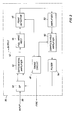
- the input 36 is from one of the receivers to the system 35.
- the pulse is supplied to an AGC operational amplifier 38.
- This amplifier has an input gain control signal which controls the gain of the amplifier 38.
- the amplifier 38 forms an output which is proportional to the gain and input signal.
- the output has the form of a signal applied on two conductors to a differential amplifier 40.
- This amplifier forms an output on a conductor 42 which is the output of the system.
- the system however includes a feedback loop which is connected from the output to obtain the AGC function.
- the feedback loop incorporates a full wave rectifier 44.
- the system is therefore able to handle both positive and negative signals. They are rectified, thereby forming a procession of pulses from the full wave rectifier and which pulses are input to the peak detector 46.
- the peak detector 46 detects a specified peak during its operation. If it operates for the entire cycle of the pulse train input to the detector 46, it will normally select the largest peak.
- the duration of operation of the peak detector is controlled by a timing circuit 48 to be described in detail hereinafter.
- the timing circuit forms a signal input to the peak detector 46 which gates the detector 46 off and on.
- the detector 46 is held on for a specified interval, thereby defining the portion of the received data to be evaluated for peak value.
- the peak signal is detected and supplied through an amplifier and input to a sample and hold amplifier 50.
- An amplifier 52 is at the input of the amplifier 50.
- the sample and hold amplifier 50 is operated at a timed moment. It is operated for a specified interval as determined by the timing circuit 48.
- the timing circuit 48 triggers the sample and hold amplifier 50 to operate to thereby fix a specified output signal.
- This output signal is supplied to a filter circuit 54.
- This circuit limits the harmonic content of the sample and hold signal passed through it; in fact, the filter provides a signal passband as a function of frequency, thereby enabling the filter circuit 54 to determine a feedback signal to be applied to the AGC operational amplifier 38.
- the operational amplifier 38 is operated at gain level determined by the gain control signal input to it.
- the timing circuit 48 operates the peak detector for a specified time interval of sufficient length to observe the data of interest.
- the timing circuit 48 will operate the sample and hold amplifier 50 to evaluate only the portion of the received signal which has data of interest.
- the timing circuit 48 causes the sample and hold circuit 50 to form a feedback signal which is applied by the feedback loop to the AGC operational amplifier 38, thereby regulating the timing of its operation to the specified interval. This timed operation then limits the dynamic range of the feedback loop.
- the received signal may have a dynamic range from the smallest readible input to the largest peak of 1,000 times larger or perhaps even greater, the range exceeds the dynamic range of some data reduction or data handling systems.
- the specified interval of interest is located and the gain of the system is controlled in that interval so that the signal dynamic range is within specified limits.
- the output data it is desirable that the output data have sixteen gray levels. This limited response range enables the sixteen levels to be obtained.
- Fig. 3 of the drawings Attention is next directed to Fig. 3 of the drawings.
- two receivers are shown. They are conveniently the receivers 20 and 22 shown in Fig. 1. They form input signals to the same AGC circuit shown in Fig. 2 and which is now found in Fig. 3. That circuit was previously identified as the AGC system 35. Again, in Fig. 3 the system 35 is included. It is arranged somewhat differently.
- the filter 54 is also shown in Fig. 3.
- the timing circuit 48 is connected to a timed source. The timing or firing signal is timed by receiver operation. In this instance, it is connected to the receiver 20 as a trigger source.
- the switched signals for the AGC are processed wherein the gain of the AGC circuit is set by the signal from the first receiver and the gain is held at the same level for the signal for the second receiver.
- the switch alternates, passing alternate signals from the two receivers.
- the foregoing sets forth one embodiment of the AGC control system and an alternate arrangement in which it is used with different inputs. Modifications can be accommodated without departing from the structure which is set forth. For instance, one modification is substitution of a halfway rectifier for the full rectifier. This can be done where the signal of interest is substantially unidirectional.
- the peak detector 46 is typically gated by the timing circuit 48.
- the gating signal is variable in the system as shown. If circumstances permit, it can be fixed by the time of the transmitted pulse. That is, the timing circuit 48 might be simplified by simply tying the input of the timing circuit 48 to the acoustic pulse transmitter, thereby timing operation of the AGC control system of this invention on occurrence of a transmitted pulse.
- Another important factor is to note the incorporation of the filter 54. This limits the frequency content input to the AGC operational amplifier. This limitation prevents destabilized operation of the feedback loop as a result of feeding excessive rate of change through the feedback loop, thereby altering the gain in an uncontrollable fashion.
Landscapes
- Engineering & Computer Science (AREA)
- Remote Sensing (AREA)
- Physics & Mathematics (AREA)
- Life Sciences & Earth Sciences (AREA)
- Acoustics & Sound (AREA)
- Environmental & Geological Engineering (AREA)
- Geology (AREA)
- General Life Sciences & Earth Sciences (AREA)
- General Physics & Mathematics (AREA)
- Geophysics (AREA)
- Geophysics And Detection Of Objects (AREA)
Applications Claiming Priority (2)
| Application Number | Priority Date | Filing Date | Title |
|---|---|---|---|
| US560294 | 1983-12-12 | ||
| US06/560,294 US4610006A (en) | 1983-12-12 | 1983-12-12 | Automatic control system for acoustic logging |
Publications (2)
| Publication Number | Publication Date |
|---|---|
| EP0145428A2 true EP0145428A2 (fr) | 1985-06-19 |
| EP0145428A3 EP0145428A3 (fr) | 1986-08-13 |
Family
ID=24237170
Family Applications (1)
| Application Number | Title | Priority Date | Filing Date |
|---|---|---|---|
| EP84308371A Withdrawn EP0145428A3 (fr) | 1983-12-12 | 1984-12-03 | Système de commande automatique pour diagraphie sonique |
Country Status (5)
| Country | Link |
|---|---|
| US (1) | US4610006A (fr) |
| EP (1) | EP0145428A3 (fr) |
| AR (1) | AR241167A1 (fr) |
| AU (1) | AU3646684A (fr) |
| CA (1) | CA1222046A (fr) |
Cited By (3)
| Publication number | Priority date | Publication date | Assignee | Title |
|---|---|---|---|---|
| FR2607263A1 (fr) * | 1986-11-26 | 1988-05-27 | Shell Int Research | Appareil de production d'images des trous de sonde |
| CN103256044A (zh) * | 2012-12-19 | 2013-08-21 | 电子科技大学 | 一种随钻声波信号处理装置 |
| CN106256989A (zh) * | 2015-06-18 | 2016-12-28 | 中国石油化工股份有限公司 | 一种井下随钻噪声采集系统 |
Families Citing this family (7)
| Publication number | Priority date | Publication date | Assignee | Title |
|---|---|---|---|---|
| FR2710757B1 (fr) * | 1993-09-30 | 1995-12-15 | Inst Francais Du Petrole | Méthode et dispositif d'acquisition de signaux sismiques. |
| US5844444A (en) * | 1997-02-14 | 1998-12-01 | Macronix International Co., Ltd. | Wide dynamic input range transconductor-based amplifier circuit for speech signal processing |
| US5986749A (en) | 1997-09-19 | 1999-11-16 | Cidra Corporation | Fiber optic sensing system |
| US6305227B1 (en) | 1998-09-02 | 2001-10-23 | Cidra Corporation | Sensing systems using quartz sensors and fiber optics |
| US6137621A (en) * | 1998-09-02 | 2000-10-24 | Cidra Corp | Acoustic logging system using fiber optics |
| US6227114B1 (en) | 1998-12-29 | 2001-05-08 | Cidra Corporation | Select trigger and detonation system using an optical fiber |
| CN102094624B (zh) * | 2009-12-14 | 2013-10-30 | 西安威尔罗根能源科技有限公司 | 一种微球聚焦测井主电流的供电电路 |
Family Cites Families (9)
| Publication number | Priority date | Publication date | Assignee | Title |
|---|---|---|---|---|
| US3394315A (en) * | 1964-11-23 | 1968-07-23 | Gen Dynamics Corp | Automatic gain control system having wide dynamic range |
| US3289157A (en) * | 1965-12-16 | 1966-11-29 | Dresser Ind | Automatic gain control in acoustic well logging systems |
| FR1506276A (fr) * | 1966-01-18 | 1967-12-22 | Inst Francais Du Petrole | Dispositif pour la commande automatique binaire de gain d'un amplificateur |
| US3488604A (en) * | 1967-09-01 | 1970-01-06 | Sperry Rand Corp | Automatic pulsed-signal amplitude normalizer |
| US3958213A (en) * | 1975-01-03 | 1976-05-18 | Gte Sylvania Incorporated | Adaptive gain control and method for signal processor |
| US4112384A (en) * | 1977-05-24 | 1978-09-05 | Morgan Industries | Controlled recovery automatic gain control amplifier |
| JPS6059772B2 (ja) * | 1979-01-26 | 1985-12-26 | 株式会社日立製作所 | アナログ・デイジタル変換器 |
| US4371842A (en) * | 1980-10-24 | 1983-02-01 | Sperry Corporation | Self-adjusting dual mode automatic gain control circuit |
| US4463320A (en) * | 1982-07-06 | 1984-07-31 | Rockwell International Corporation | Automatic gain control circuit |
-
1983
- 1983-12-12 US US06/560,294 patent/US4610006A/en not_active Expired - Fee Related
-
1984
- 1984-11-29 CA CA000468936A patent/CA1222046A/fr not_active Expired
- 1984-12-03 EP EP84308371A patent/EP0145428A3/fr not_active Withdrawn
- 1984-12-10 AU AU36466/84A patent/AU3646684A/en not_active Abandoned
- 1984-12-12 AR AR298935A patent/AR241167A1/es active
Cited By (4)
| Publication number | Priority date | Publication date | Assignee | Title |
|---|---|---|---|---|
| FR2607263A1 (fr) * | 1986-11-26 | 1988-05-27 | Shell Int Research | Appareil de production d'images des trous de sonde |
| CN103256044A (zh) * | 2012-12-19 | 2013-08-21 | 电子科技大学 | 一种随钻声波信号处理装置 |
| CN103256044B (zh) * | 2012-12-19 | 2016-01-06 | 电子科技大学 | 一种随钻声波信号处理装置 |
| CN106256989A (zh) * | 2015-06-18 | 2016-12-28 | 中国石油化工股份有限公司 | 一种井下随钻噪声采集系统 |
Also Published As
| Publication number | Publication date |
|---|---|
| CA1222046A (fr) | 1987-05-19 |
| EP0145428A3 (fr) | 1986-08-13 |
| AR241167A2 (es) | 1991-12-30 |
| AR241167A1 (es) | 1991-12-30 |
| US4610006A (en) | 1986-09-02 |
| AU3646684A (en) | 1985-06-20 |
Similar Documents
| Publication | Publication Date | Title |
|---|---|---|
| US4293936A (en) | Telemetry system | |
| CA1086417A (fr) | Dispositif automatique a seuil de declenchement et son utilisation | |
| US4658383A (en) | Automatic gain control of digitized full trace acoustic signal in a borehole | |
| US3794976A (en) | Methods and apparatus for acoustically investigating earth formations using shear waves | |
| EP0145428A2 (fr) | Système de commande automatique pour diagraphie sonique | |
| US5724308A (en) | Programmable acoustic borehole logging | |
| US4293934A (en) | Circumferential acoustic device | |
| CA2030520A1 (fr) | Dispositif et procede de controle d'un forage par analyse des vibrations | |
| US4414651A (en) | Integrated well logging system and method | |
| CA1281117C (fr) | Methode d'excitation pour l'emetteur du type cintreuse d'un diagraphe de sondage pour engendrer sequentiellement des ondes acoustiques de compression et de propagation dans les tubes | |
| US4797668A (en) | Acoustic well logging system having multiplexed filter digitizing | |
| KR910002146A (ko) | 노이즈 정합 방법 및 수신기 | |
| US3909775A (en) | Methods and apparatus for acoustic logging through casing | |
| EP0231063B1 (fr) | Procédé de diagraphie des puits pour déterminer l'atténuation des ondes acoustiques du tube dans les formations sous surface le long du puits | |
| US4684947A (en) | Simultaneous digitizing apparatus for an acoustic tool | |
| EP0073335A1 (fr) | Procédé et dispositif pour la mesure combinée de la cimentation et la diagraphie acoustique | |
| US4845616A (en) | Method for extracting acoustic velocities in a well borehole | |
| US3691518A (en) | Methods and apparatus for acoustic travel time and cement bond logging | |
| US4172250A (en) | Acoustic well logging with threshold adjustment | |
| GB1184880A (en) | Acoustic Well Logging Apparatus and Method for Detecting Fractures | |
| US4319346A (en) | Acoustic frequency spectrum logging | |
| US4419748A (en) | Continuous wave sonic logging | |
| CA1119283A (fr) | Methode et dispositif d'inspection dynamique d'un forage | |
| US4349896A (en) | Digital acoustic logging method and apparatus | |
| CA1162633A (fr) | Diagraphie acoustique a detecteur de niveau d'energie pour forage |
Legal Events
| Date | Code | Title | Description |
|---|---|---|---|
| PUAI | Public reference made under article 153(3) epc to a published international application that has entered the european phase |
Free format text: ORIGINAL CODE: 0009012 |
|
| AK | Designated contracting states |
Designated state(s): AT DE FR GB IT NL SE |
|
| PUAL | Search report despatched |
Free format text: ORIGINAL CODE: 0009013 |
|
| AK | Designated contracting states |
Kind code of ref document: A3 Designated state(s): AT DE FR GB IT NL SE |
|
| 17P | Request for examination filed |
Effective date: 19861105 |
|
| 17Q | First examination report despatched |
Effective date: 19880530 |
|
| STAA | Information on the status of an ep patent application or granted ep patent |
Free format text: STATUS: THE APPLICATION IS DEEMED TO BE WITHDRAWN |
|
| 18D | Application deemed to be withdrawn |
Effective date: 19880705 |
|
| RIN1 | Information on inventor provided before grant (corrected) |
Inventor name: MACDONALD, CLYDE OSMOND |