EP0145430A2 - Signal-Übertragungsverfahren - Google Patents
Signal-Übertragungsverfahren Download PDFInfo
- Publication number
- EP0145430A2 EP0145430A2 EP84308374A EP84308374A EP0145430A2 EP 0145430 A2 EP0145430 A2 EP 0145430A2 EP 84308374 A EP84308374 A EP 84308374A EP 84308374 A EP84308374 A EP 84308374A EP 0145430 A2 EP0145430 A2 EP 0145430A2
- Authority
- EP
- European Patent Office
- Prior art keywords
- resonant
- antenna
- frequency
- transmitting
- receiving
- Prior art date
- Legal status (The legal status is an assumption and is not a legal conclusion. Google has not performed a legal analysis and makes no representation as to the accuracy of the status listed.)
- Granted
Links
Images

Classifications
-
- H—ELECTRICITY
- H04—ELECTRIC COMMUNICATION TECHNIQUE
- H04B—TRANSMISSION
- H04B5/00—Near-field transmission systems, e.g. inductive or capacitive transmission systems
- H04B5/20—Near-field transmission systems, e.g. inductive or capacitive transmission systems characterised by the transmission technique; characterised by the transmission medium
- H04B5/22—Capacitive coupling
-
- A—HUMAN NECESSITIES
- A61—MEDICAL OR VETERINARY SCIENCE; HYGIENE
- A61F—FILTERS IMPLANTABLE INTO BLOOD VESSELS; PROSTHESES; DEVICES PROVIDING PATENCY TO, OR PREVENTING COLLAPSING OF, TUBULAR STRUCTURES OF THE BODY, e.g. STENTS; ORTHOPAEDIC, NURSING OR CONTRACEPTIVE DEVICES; FOMENTATION; TREATMENT OR PROTECTION OF EYES OR EARS; BANDAGES, DRESSINGS OR ABSORBENT PADS; FIRST-AID KITS
- A61F2250/00—Special features of prostheses classified in groups A61F2/00 - A61F2/26 or A61F2/82 or A61F9/00 or A61F11/00 or subgroups thereof
- A61F2250/0001—Means for transferring electromagnetic energy to implants
- A61F2250/0002—Means for transferring electromagnetic energy to implants for data transfer
-
- H—ELECTRICITY
- H04—ELECTRIC COMMUNICATION TECHNIQUE
- H04B—TRANSMISSION
- H04B5/00—Near-field transmission systems, e.g. inductive or capacitive transmission systems
- H04B5/20—Near-field transmission systems, e.g. inductive or capacitive transmission systems characterised by the transmission technique; characterised by the transmission medium
- H04B5/24—Inductive coupling
- H04B5/26—Inductive coupling using coils
Definitions
- the present invention relates generally to signal transmission systems and more particularly to signal transmission systems which transmit a signal across a boundary with close proximity between transmitting and receiving antennas.
- the environment where the signal transmission system of the present invention operates is in a system where the transmission is over a short distance across a barrier.
- An example of this environment is the use of a signal transmission system with a hearing prosthetic device in which a receiver is implanted within the body to drive an electrode to electrically stimulate the auditory nerve.
- a transmitting antenna is positioned in close proximity to the receiving antenna but across the cutaneous barrier. Signals representing sound are then transmitted across the cutaneous boundary to the receiver for ultimate delivery to the electrode.
- the signal transmission system then avoids the use of a percutaneous plug and its attendant potential for infection.
- the transmitter and receiver of the signal transmission system use resonant LC antennas to transmit and receive a small amount of electrical energy over a short distance, e.g. centimeters over the skin boundary.
- the present invention provides a signal transmission system for use in transmitting a signal across a barrier.
- a radio frequency receiver is utilized on one side of the barrier.
- a receiving resonant antenna is positioned on that one side of the barrier and is operatively coupled to the radio frequency receiver.
- the receiving resonant antenna has a resonant frequency.
- a transmitting resonant antenna is positioned on the opposite side of the barrier nearby the receiving resonant antenna.
- the transmitting resonant antenna has a resonant frequency.
- the resonant frequency of the receiving resonant antenna is relatively close to the resonant frequency of the transmitting resonant antenna.
- a radio frequency transmitter is positioned on the same side of the barrier as the transmitting resonant antenna and is operatively coupled to the transmitting resonant antenna.
- the radio frequency transmitter has an oscillator having a frequency of oscillation driving a resonant load.
- the resonant load includes the transmitting resonant antenna inductively coupled with the receiving resonant antenna.
- the frequency of oscillation of the oscillator is at least partially determined by the resonant frequency of the resonant load.
- the transfer characteristic of the signal transmission system is relatively independent of the distance between the transmitting resonant antenna and the receiving resonant antenna, of radial misalignment between the transmitting resonant antenna and of the receiving resonant antenna and resonant frequency mismatch of the transmitting resonant antenna and the receiving resonant antenna.
- the signal transmission system is adapted for use in a transcutaneous environment wherein the receiving resonant antenna and radio frequency receiver are positioned for subcutaneous use and the transmitting resonant antenna and the radio frequency transmitter are positioned for supercutaneous use.
- a signal transmission system constructed in this manner provides a transmitter which is self-resonant, i.e. which oscillates at the resonant frequency of the resonant load which includes the tranmsitting and receiving antennas.
- the reason this stability in signal level from the receiver is achieved is due to the effect of the receiving antenna on the resonant frequency of the transmitting antenna coupled with the dependence of the frequency of oscillation of the transmitter on the resonance of the resonant load. This effect causes the operating frequency of the signal transmission system to change such that the output voltage from the receiver stays virtually constant.
- FIG. 1 illustrates a block diagram of the signal transmission system 10 of the present invention.
- a transmitter 12 is operatively coupled to a transmitting antenna 14 positioned on one side of a boundary or barrier 16.
- a receiver 18 is operatively coupled to a receiving antenna 20.
- the transmitting antenna consists of a resonant LC circuit involving inductor 22 and capacitor 24.
- receiving antenna 20 also comprises an LC circuit consisting of inductor 26 and capacitor 28.
- While both the transmitting antenna 14 and the receiving antenna 20 are shown as tank circuits having a parallel connection of an inductor (22, 26) and a capacitor (24, 28, respectively) various other combinations of capacitive and inductive elements can be formed to comprise a resonant circuit such as, and including, the series combination of an inductor and a capacitor.
- the receiving resonant antenna 20 has a resonant frequency which is dependent upon the tank circuit comprising inductor 26 and capacitor 28. Similarily, transmitting antenna 14, in the absence of other factors, has a resonant frequency which is dependent upon the tank circuit comprising inductor 22 and capacitor 24. Inductor 22 of the transmitting resonant antenna 14 and inductor 26 of the receiving resonant antenna 20 are positioned for relatively close lateral alignment along barrier 16 and are also positioned within fairly close proximity across barrier 16, i.e. axial alignment. In a preferred embodiment, the axial spacing between the transmitting antenna 14 and the receiving antenna 20 is chosen such that axial spacing is less than the critical coupling distance.
- the resonant frequency of the transmitting antenna 14 is chosen so that it is relatively close to the resonant frequency of the receiving antenna 20. Relatively close, for purposes of this discussion, generally means in the range of being within ten percent. Certainly variations in the resonant frequencies of transmitting antenna 14 and receiving antenna 20 can be twenty percent and even greater. However, it is generally preferred that the resonant frequencies of the transmitting antenna 14 and the receiving antenna 20 be within ten percent of each other.
- Transmitter 12 has an oscillator which drives a resonant load which includes transmitting antenna 14 and its inductive coupling with receiving antenna 20. Further, the frequency of oscillation of the oscillator of transmitter 12 is at least partially determined by the frequency of the resonant load, i.e.
- the frequency of oscillation of the oscillator of transmitter 12 is primarily determined by the resonance of the resonant load and in a still preferred embodiment, is identical to the resonant frequency of the resonant load.
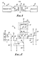
- FIG. 2 illustrates a schematic diagram of the transmitter 12 in conjunction with the transmitting antenna 14.
- Transmitting antenna 14 consists of a tank circuit comprising inductor 22 and capacitor 24 as illustrated in Figure 1.
- the signal to the transmitter 12 is provided through junction block 30 which provides a signal 32, a voltage source 34 and the ground return for the voltage source 36.
- the signal 32 drives resistor 38, resistor 40, resistor 42, operational amplifier 44 to feed transistor 46 and resistor 48 forms a constant current source, controlled by signal 32.
- Transistor 46 of the constant current source feeds transistors 50 and 52 which together with associated resistors 54, 56, 58, 60, 62, 64 and 66, transistor 68 and capacitor 70 and 72 form the oscillator circuit of the transmitter 12.
- This oscillator drives antenna 14 (in the form of inductor 22 along with capacitor 24) to form, in the absence of other circumstances, the resonant load of the oscillator of the transmitter 12.
- Capacitor 76 is a decoupling capacitor. A distinguishing feature of transmitter 12 is that it contains one oscillator whose frequency of oscillation of that oscillator is dependent upon the resonant load which that oscillator drives.
- FIG 3 represents a schematic diagram of receiver 18 and receiving antenna 20.
- receiving antenna 20 consists of inductor 26 parallel coupled to capacitor 28.
- capacitor 28 Of course, various other tank circuits are envisioned for this receiving antenna 20.
- Receiving antenna 20 drives diode 82, capacitor 84 with resistor 86, which together with DC blocking capacitor 88 demodulate the signal for transmission to an electrode or other load for the transmitted signal.
- the load is an electrode which is implanted in the ear as an auditory hearing prosthesis to stimulate body tissue and, in particular, the auditory nerve.
- Table 1 illustrates examples of values for the components utilized in the transmitter described in Figure 2 and the receiver described in Figure 3.
- Figure 4 is a graph in which the spacing between the antenna coils of the transmitting antenna 14 and the receiving antenna 20 is plotted against the amplitude of the voltage of the received signal at the receiver 18.
- the slope of the curve is at a minimum at that particular spacing. It is at this spacing between the coils of the transmitting antenna 14 and the receiving antenna 20 that variations in the antenna spacing provide a minimal effect on the voltage amplitude of the received signal.
- the point 94 illustrated in Figure 4 is the point of "critical coupling" between the transmitting antenna 14 and the receiving antenna 20.
- Figure 5 illustrates a graph in which the amplitude of the received signal 96 is plotted against the frequency 98 of operation of the transmitter oscillator.
- line 100 on the graph illustrates the effect of variations in the frequency of operation of the signal transmission system upon the amplitude of the received signal 96. From the graph it can be seen that there is a preferred frequency of operation 102 at which the amplitude of the received signal 96 is at a maximum and which variations in the frequency 98 of operation of the signal transmission system will result in minimal changes in the received amplitude 96 due to the minimum of slope of the curve 100.
- the curve in Figure 5 differs.
- An example of the curve representing the received amplitude 96 as a function of the frequncy 98 of operation is shown by curve 104. Instead of a single peak at frequency 102, the curve 104 demonstrates that there are really two amplitude peaks occurring on either side of frequency of 102. Note that the receiving amplitude 96 at the maximum in curve 104 is virtually identical to the received amplitude 96 of curve 100. That amplitude, however, is achieved at a different frequency of oscillation. Thus, the preferred frequency of oscillation for curve 104 differs from the frequency of operation for curve 100.
- the frequency of oscillation of the oscillator of transmitter 12 will automatically track to either frequency 100 or 108 maintaining the virtually identical received amplitude 96, albeit at a different frequency.
- the unique transmitter 12, transmitting antenna 14 positioned in conjunction with receiving antenna 20 and receiver 18 provide a unique signal transmission system in which the received amplitude 96 of the signal at the receiver 18 is relatively independent of variations in coil misalignment between the transmitting antenna 14 and receiving antenna 20 as well as mismatches between the resonant frequencies of the transmitting antenna 14 and the receiving antenna 20. This is because the frequency of oscillation of the oscillator of transmitter 12 will automatically track to the proper frequency due to the resonant load which that oscillator drives.
Landscapes
- Engineering & Computer Science (AREA)
- Computer Networks & Wireless Communication (AREA)
- Signal Processing (AREA)
- Near-Field Transmission Systems (AREA)
- Prostheses (AREA)
- Measuring Pulse, Heart Rate, Blood Pressure Or Blood Flow (AREA)
- Support Of Aerials (AREA)
- Reduction Or Emphasis Of Bandwidth Of Signals (AREA)
- Radar Systems Or Details Thereof (AREA)
- Radio Relay Systems (AREA)
- Transmitters (AREA)
Priority Applications (1)
| Application Number | Priority Date | Filing Date | Title |
|---|---|---|---|
| AT84308374T ATE63808T1 (de) | 1983-12-09 | 1984-12-03 | Signal-uebertragungsverfahren. |
Applications Claiming Priority (2)
| Application Number | Priority Date | Filing Date | Title |
|---|---|---|---|
| US55992383A | 1983-12-09 | 1983-12-09 | |
| US559923 | 1983-12-09 |
Publications (3)
| Publication Number | Publication Date |
|---|---|
| EP0145430A2 true EP0145430A2 (de) | 1985-06-19 |
| EP0145430A3 EP0145430A3 (en) | 1987-07-01 |
| EP0145430B1 EP0145430B1 (de) | 1991-05-29 |
Family
ID=24235625
Family Applications (1)
| Application Number | Title | Priority Date | Filing Date |
|---|---|---|---|
| EP84308374A Expired - Lifetime EP0145430B1 (de) | 1983-12-09 | 1984-12-03 | Signal-Übertragungsverfahren |
Country Status (6)
| Country | Link |
|---|---|
| EP (1) | EP0145430B1 (de) |
| JP (1) | JPH0797758B2 (de) |
| AT (1) | ATE63808T1 (de) |
| AU (1) | AU570741B2 (de) |
| CA (1) | CA1226624A (de) |
| DE (1) | DE3484647D1 (de) |
Cited By (19)
| Publication number | Priority date | Publication date | Assignee | Title |
|---|---|---|---|---|
| GB2202414A (en) * | 1987-03-10 | 1988-09-21 | Oxley Dev Co Ltd | Transmission of power and/or data |
| WO1989010651A1 (fr) * | 1988-04-28 | 1989-11-02 | Every-Sys Ag | Dispositif de transmission electrique |
| WO1991003887A1 (en) * | 1989-09-07 | 1991-03-21 | Cochlear Pty. Limited | Three wire system for cochlear implant processor |
| FR2692777A1 (fr) * | 1992-06-26 | 1993-12-31 | Alfieri Patrick | Dispositif de commande d'un organe artificiel implanté dans le corps humain. |
| WO1997015125A1 (en) * | 1995-10-19 | 1997-04-24 | The University Of Melbourne | Embedded data link and protocol |
| AU2005201357B2 (en) * | 2004-03-31 | 2007-03-08 | Sivantos Gmbh | ITE hearing aid for the binaural aiding of a patient |
| US8108042B1 (en) | 2006-11-09 | 2012-01-31 | Greatbatch Ltd. | Capacitor and inductor elements physically disposed in series whose lumped parameters are electrically connected in parallel to form a bandstop filter |
| US8200328B2 (en) | 2005-11-11 | 2012-06-12 | Greatbatch Ltd. | Tank filters placed in series with the lead wires or circuits of active medical devices to enhance MRI compatibility |
| US8649857B2 (en) | 2006-06-08 | 2014-02-11 | Greatbatch Ltd. | Tank filters placed in series with the lead wires or circuits of active medical devices to enhance MRI compatibility |
| US8897887B2 (en) | 2006-06-08 | 2014-11-25 | Greatbatch Ltd. | Band stop filter employing a capacitor and an inductor tank circuit to enhance MRI compatibility of active medical devices |
| USRE46699E1 (en) | 2013-01-16 | 2018-02-06 | Greatbatch Ltd. | Low impedance oxide resistant grounded capacitor for an AIMD |
| US9931514B2 (en) | 2013-06-30 | 2018-04-03 | Greatbatch Ltd. | Low impedance oxide resistant grounded capacitor for an AIMD |
| US10350421B2 (en) | 2013-06-30 | 2019-07-16 | Greatbatch Ltd. | Metallurgically bonded gold pocket pad for grounding an EMI filter to a hermetic terminal for an active implantable medical device |
| US10559409B2 (en) | 2017-01-06 | 2020-02-11 | Greatbatch Ltd. | Process for manufacturing a leadless feedthrough for an active implantable medical device |
| US10561837B2 (en) | 2011-03-01 | 2020-02-18 | Greatbatch Ltd. | Low equivalent series resistance RF filter for an active implantable medical device utilizing a ceramic reinforced metal composite filled via |
| US10589107B2 (en) | 2016-11-08 | 2020-03-17 | Greatbatch Ltd. | Circuit board mounted filtered feedthrough assembly having a composite conductive lead for an AIMD |
| US10905888B2 (en) | 2018-03-22 | 2021-02-02 | Greatbatch Ltd. | Electrical connection for an AIMD EMI filter utilizing an anisotropic conductive layer |
| US10912945B2 (en) | 2018-03-22 | 2021-02-09 | Greatbatch Ltd. | Hermetic terminal for an active implantable medical device having a feedthrough capacitor partially overhanging a ferrule for high effective capacitance area |
| US11198014B2 (en) | 2011-03-01 | 2021-12-14 | Greatbatch Ltd. | Hermetically sealed filtered feedthrough assembly having a capacitor with an oxide resistant electrical connection to an active implantable medical device housing |
Families Citing this family (27)
| Publication number | Priority date | Publication date | Assignee | Title |
|---|---|---|---|---|
| EP0200321A3 (de) * | 1985-03-20 | 1987-03-11 | Ingeborg J. Hochmair | Transkutanes Signalübertragungssystem |
| US5991170A (en) * | 1998-02-03 | 1999-11-23 | Sony Corporation | Equipment and method for transmitting electric power |
| US9061139B2 (en) | 1998-11-04 | 2015-06-23 | Greatbatch Ltd. | Implantable lead with a band stop filter having a capacitor in parallel with an inductor embedded in a dielectric body |
| US6701176B1 (en) | 1998-11-04 | 2004-03-02 | Johns Hopkins University School Of Medicine | Magnetic-resonance-guided imaging, electrophysiology, and ablation |
| US7853325B2 (en) | 2001-04-13 | 2010-12-14 | Greatbatch Ltd. | Cylindrical bandstop filters for medical lead systems |
| US20070088416A1 (en) | 2001-04-13 | 2007-04-19 | Surgi-Vision, Inc. | Mri compatible medical leads |
| CA2482202C (en) | 2001-04-13 | 2012-07-03 | Surgi-Vision, Inc. | Systems and methods for magnetic-resonance-guided interventional procedures |
| US8457760B2 (en) | 2001-04-13 | 2013-06-04 | Greatbatch Ltd. | Switched diverter circuits for minimizing heating of an implanted lead and/or providing EMI protection in a high power electromagnetic field environment |
| US8977355B2 (en) | 2001-04-13 | 2015-03-10 | Greatbatch Ltd. | EMI filter employing a capacitor and an inductor tank circuit having optimum component values |
| US8219208B2 (en) | 2001-04-13 | 2012-07-10 | Greatbatch Ltd. | Frequency selective passive component networks for active implantable medical devices utilizing an energy dissipating surface |
| US8989870B2 (en) | 2001-04-13 | 2015-03-24 | Greatbatch Ltd. | Tuned energy balanced system for minimizing heating and/or to provide EMI protection of implanted leads in a high power electromagnetic field environment |
| US9295828B2 (en) | 2001-04-13 | 2016-03-29 | Greatbatch Ltd. | Self-resonant inductor wound portion of an implantable lead for enhanced MRI compatibility of active implantable medical devices |
| US7787958B2 (en) | 2001-04-13 | 2010-08-31 | Greatbatch Ltd. | RFID detection and identification system for implantable medical lead systems |
| US8509913B2 (en) | 2001-04-13 | 2013-08-13 | Greatbatch Ltd. | Switched diverter circuits for minimizing heating of an implanted lead and/or providing EMI protection in a high power electromagnetic field environment |
| US8712544B2 (en) | 2001-04-13 | 2014-04-29 | Greatbatch Ltd. | Electromagnetic shield for a passive electronic component in an active medical device implantable lead |
| US7899551B2 (en) | 2001-04-13 | 2011-03-01 | Greatbatch Ltd. | Medical lead system utilizing electromagnetic bandstop filters |
| WO2003102614A1 (en) | 2002-05-29 | 2003-12-11 | Surgi-Vision, Inc. | Magnetic resonance probes |
| US8224462B2 (en) | 2005-11-11 | 2012-07-17 | Greatbatch Ltd. | Medical lead system utilizing electromagnetic bandstop filters |
| US7702387B2 (en) | 2006-06-08 | 2010-04-20 | Greatbatch Ltd. | Tank filters adaptable for placement with a guide wire, in series with the lead wires or circuits of active medical devices to enhance MRI compatibility |
| US8903505B2 (en) | 2006-06-08 | 2014-12-02 | Greatbatch Ltd. | Implantable lead bandstop filter employing an inductive coil with parasitic capacitance to enhance MRI compatibility of active medical devices |
| US9042999B2 (en) | 2006-06-08 | 2015-05-26 | Greatbatch Ltd. | Low loss band pass filter for RF distance telemetry pin antennas of active implantable medical devices |
| US9468750B2 (en) | 2006-11-09 | 2016-10-18 | Greatbatch Ltd. | Multilayer planar spiral inductor filter for medical therapeutic or diagnostic applications |
| US9031670B2 (en) | 2006-11-09 | 2015-05-12 | Greatbatch Ltd. | Electromagnetic shield for a passive electronic component in an active medical device implantable lead |
| US9108066B2 (en) | 2008-03-20 | 2015-08-18 | Greatbatch Ltd. | Low impedance oxide resistant grounded capacitor for an AIMD |
| US10080889B2 (en) | 2009-03-19 | 2018-09-25 | Greatbatch Ltd. | Low inductance and low resistance hermetically sealed filtered feedthrough for an AIMD |
| US8447414B2 (en) | 2008-12-17 | 2013-05-21 | Greatbatch Ltd. | Switched safety protection circuit for an AIMD system during exposure to high power electromagnetic fields |
| US9427596B2 (en) | 2013-01-16 | 2016-08-30 | Greatbatch Ltd. | Low impedance oxide resistant grounded capacitor for an AIMD |
Family Cites Families (4)
| Publication number | Priority date | Publication date | Assignee | Title |
|---|---|---|---|---|
| US4223679A (en) * | 1979-02-28 | 1980-09-23 | Pacesetter Systems, Inc. | Telemetry means for tissue stimulator system |
| AU562749B2 (en) * | 1982-08-20 | 1987-06-18 | University Of Melbourne, The | Hearing prosthesis |
| US4532930A (en) * | 1983-04-11 | 1985-08-06 | Commonwealth Of Australia, Dept. Of Science & Technology | Cochlear implant system for an auditory prosthesis |
| EP0200321A3 (de) * | 1985-03-20 | 1987-03-11 | Ingeborg J. Hochmair | Transkutanes Signalübertragungssystem |
-
1984
- 1984-10-23 CA CA000466070A patent/CA1226624A/en not_active Expired
- 1984-11-01 AU AU34910/84A patent/AU570741B2/en not_active Ceased
- 1984-12-03 EP EP84308374A patent/EP0145430B1/de not_active Expired - Lifetime
- 1984-12-03 DE DE8484308374T patent/DE3484647D1/de not_active Expired - Fee Related
- 1984-12-03 AT AT84308374T patent/ATE63808T1/de not_active IP Right Cessation
- 1984-12-07 JP JP59257725A patent/JPH0797758B2/ja not_active Expired - Lifetime
Cited By (26)
| Publication number | Priority date | Publication date | Assignee | Title |
|---|---|---|---|---|
| GB2202414A (en) * | 1987-03-10 | 1988-09-21 | Oxley Dev Co Ltd | Transmission of power and/or data |
| WO1989010651A1 (fr) * | 1988-04-28 | 1989-11-02 | Every-Sys Ag | Dispositif de transmission electrique |
| WO1991003887A1 (en) * | 1989-09-07 | 1991-03-21 | Cochlear Pty. Limited | Three wire system for cochlear implant processor |
| FR2692777A1 (fr) * | 1992-06-26 | 1993-12-31 | Alfieri Patrick | Dispositif de commande d'un organe artificiel implanté dans le corps humain. |
| WO1997015125A1 (en) * | 1995-10-19 | 1997-04-24 | The University Of Melbourne | Embedded data link and protocol |
| US5741314A (en) * | 1995-10-19 | 1998-04-21 | Daly; Christopher Newton | Embedded data link and protocol |
| AU2005201357B2 (en) * | 2004-03-31 | 2007-03-08 | Sivantos Gmbh | ITE hearing aid for the binaural aiding of a patient |
| US8200328B2 (en) | 2005-11-11 | 2012-06-12 | Greatbatch Ltd. | Tank filters placed in series with the lead wires or circuits of active medical devices to enhance MRI compatibility |
| US8463375B2 (en) | 2005-11-11 | 2013-06-11 | Greatbatch Ltd. | Tank filters placed in series with the lead wires or circuits of active medical devices to enhance MRI compatability |
| US8649857B2 (en) | 2006-06-08 | 2014-02-11 | Greatbatch Ltd. | Tank filters placed in series with the lead wires or circuits of active medical devices to enhance MRI compatibility |
| US8897887B2 (en) | 2006-06-08 | 2014-11-25 | Greatbatch Ltd. | Band stop filter employing a capacitor and an inductor tank circuit to enhance MRI compatibility of active medical devices |
| US8108042B1 (en) | 2006-11-09 | 2012-01-31 | Greatbatch Ltd. | Capacitor and inductor elements physically disposed in series whose lumped parameters are electrically connected in parallel to form a bandstop filter |
| US10596369B2 (en) | 2011-03-01 | 2020-03-24 | Greatbatch Ltd. | Low equivalent series resistance RF filter for an active implantable medical device |
| US11198014B2 (en) | 2011-03-01 | 2021-12-14 | Greatbatch Ltd. | Hermetically sealed filtered feedthrough assembly having a capacitor with an oxide resistant electrical connection to an active implantable medical device housing |
| US11071858B2 (en) | 2011-03-01 | 2021-07-27 | Greatbatch Ltd. | Hermetically sealed filtered feedthrough having platinum sealed directly to the insulator in a via hole |
| US10561837B2 (en) | 2011-03-01 | 2020-02-18 | Greatbatch Ltd. | Low equivalent series resistance RF filter for an active implantable medical device utilizing a ceramic reinforced metal composite filled via |
| USRE46699E1 (en) | 2013-01-16 | 2018-02-06 | Greatbatch Ltd. | Low impedance oxide resistant grounded capacitor for an AIMD |
| US10350421B2 (en) | 2013-06-30 | 2019-07-16 | Greatbatch Ltd. | Metallurgically bonded gold pocket pad for grounding an EMI filter to a hermetic terminal for an active implantable medical device |
| US9931514B2 (en) | 2013-06-30 | 2018-04-03 | Greatbatch Ltd. | Low impedance oxide resistant grounded capacitor for an AIMD |
| US10589107B2 (en) | 2016-11-08 | 2020-03-17 | Greatbatch Ltd. | Circuit board mounted filtered feedthrough assembly having a composite conductive lead for an AIMD |
| US10559409B2 (en) | 2017-01-06 | 2020-02-11 | Greatbatch Ltd. | Process for manufacturing a leadless feedthrough for an active implantable medical device |
| US10905888B2 (en) | 2018-03-22 | 2021-02-02 | Greatbatch Ltd. | Electrical connection for an AIMD EMI filter utilizing an anisotropic conductive layer |
| US10912945B2 (en) | 2018-03-22 | 2021-02-09 | Greatbatch Ltd. | Hermetic terminal for an active implantable medical device having a feedthrough capacitor partially overhanging a ferrule for high effective capacitance area |
| US11712571B2 (en) | 2018-03-22 | 2023-08-01 | Greatbatch Ltd. | Electrical connection for a hermetic terminal for an active implantable medical device utilizing a ferrule pocket |
| US12064639B2 (en) | 2018-03-22 | 2024-08-20 | Greatbatch Ltd. | Electrical connection for an AIMD utilizing an anisotropic conductive layer |
| US12343548B2 (en) | 2018-03-22 | 2025-07-01 | Greatbatch Ltd. | Anisotropic conductive electrical connection from a conductive pathway through a ceramic casing to a circuit board electronic component housed inside the casing |
Also Published As
| Publication number | Publication date |
|---|---|
| EP0145430A3 (en) | 1987-07-01 |
| CA1226624A (en) | 1987-09-08 |
| ATE63808T1 (de) | 1991-06-15 |
| JPS60141034A (ja) | 1985-07-26 |
| DE3484647D1 (de) | 1991-07-04 |
| AU3491084A (en) | 1985-06-13 |
| AU570741B2 (en) | 1988-03-24 |
| JPH0797758B2 (ja) | 1995-10-18 |
| EP0145430B1 (de) | 1991-05-29 |
Similar Documents
| Publication | Publication Date | Title |
|---|---|---|
| EP0145430A2 (de) | Signal-Übertragungsverfahren | |
| US4654880A (en) | Signal transmission system | |
| EP0076070B1 (de) | Transkutanes Signalübertragungssystem | |
| CA1276240C (en) | Transcutaneous power and signal transmission system and methods for increased signal transmission efficiency | |
| EP0572382B1 (de) | Drei-draht-system für cochlearimplantatprozessor | |
| US6212431B1 (en) | Power transfer circuit for implanted devices | |
| US4542532A (en) | Dual-antenna transceiver | |
| US7392091B2 (en) | Implanted antenna and radio communications link | |
| CA1276242C (en) | Wide band inductive transdermal power and data link | |
| EP0179536A2 (de) | Energieübertragung für implantierte Prothesen | |
| US10547200B2 (en) | Near-field wireless power transfer system with immunity to distance and/or load variations | |
| US11387685B2 (en) | Load-induced resonance-shift-keying modulation scheme for simultaneous near-field wireless power and data transmission through a pair of inductive coils | |
| MXPA00011254A (es) | Dispositivo para la transmision de datos sin contacto. | |
| JP4332963B2 (ja) | 電磁トランスポンダの容量性変調 | |
| JPH053165B2 (de) | ||
| EP2312772A1 (de) | Sende- und Empfangsgerät und Kommunikationssystem damit | |
| US20060199560A1 (en) | Telemetry system employing DC balanced encoding | |
| CN218570221U (zh) | 一种模拟信号转发电路以及电子设备 | |
| US6415134B1 (en) | Transponder communication station provided with a transmission coil configuration with two transmission coils | |
| DE3233239A1 (de) | Telemetriesystem | |
| El Boutahiri et al. | Design of 2MHz OOK transmitter/receiver for inductive power and data transmission for biomedical implant. | |
| Zierhofer et al. | Transcutaneous transmission of digital data and energy in a cochlear prosthesis system | |
| CN111464204A (zh) | 射频电路及天线调谐电路 | |
| JPS6041333A (ja) | 電力線搬送用送信機 | |
| JPH08146U (ja) | 無線送信機 |
Legal Events
| Date | Code | Title | Description |
|---|---|---|---|
| PUAI | Public reference made under article 153(3) epc to a published international application that has entered the european phase |
Free format text: ORIGINAL CODE: 0009012 |
|
| AK | Designated contracting states |
Designated state(s): AT CH DE FR GB LI |
|
| PUAL | Search report despatched |
Free format text: ORIGINAL CODE: 0009013 |
|
| AK | Designated contracting states |
Kind code of ref document: A3 Designated state(s): AT CH DE FR GB LI |
|
| 17P | Request for examination filed |
Effective date: 19871229 |
|
| 17Q | First examination report despatched |
Effective date: 19890728 |
|
| RAP1 | Party data changed (applicant data changed or rights of an application transferred) |
Owner name: COCHLEAR CORPORATION |
|
| GRAA | (expected) grant |
Free format text: ORIGINAL CODE: 0009210 |
|
| AK | Designated contracting states |
Kind code of ref document: B1 Designated state(s): AT CH DE FR GB LI |
|
| PG25 | Lapsed in a contracting state [announced via postgrant information from national office to epo] |
Ref country code: LI Effective date: 19910529 Ref country code: CH Effective date: 19910529 Ref country code: AT Effective date: 19910529 |
|
| REF | Corresponds to: |
Ref document number: 63808 Country of ref document: AT Date of ref document: 19910615 Kind code of ref document: T |
|
| REF | Corresponds to: |
Ref document number: 3484647 Country of ref document: DE Date of ref document: 19910704 |
|
| ET | Fr: translation filed | ||
| REG | Reference to a national code |
Ref country code: CH Ref legal event code: PL |
|
| PLBE | No opposition filed within time limit |
Free format text: ORIGINAL CODE: 0009261 |
|
| STAA | Information on the status of an ep patent application or granted ep patent |
Free format text: STATUS: NO OPPOSITION FILED WITHIN TIME LIMIT |
|
| 26N | No opposition filed | ||
| PGFP | Annual fee paid to national office [announced via postgrant information from national office to epo] |
Ref country code: GB Payment date: 20001106 Year of fee payment: 17 |
|
| PGFP | Annual fee paid to national office [announced via postgrant information from national office to epo] |
Ref country code: FR Payment date: 20001122 Year of fee payment: 17 |
|
| PGFP | Annual fee paid to national office [announced via postgrant information from national office to epo] |
Ref country code: DE Payment date: 20001124 Year of fee payment: 17 |
|
| PG25 | Lapsed in a contracting state [announced via postgrant information from national office to epo] |
Ref country code: GB Free format text: LAPSE BECAUSE OF NON-PAYMENT OF DUE FEES Effective date: 20011203 |
|
| REG | Reference to a national code |
Ref country code: GB Ref legal event code: IF02 |
|
| PG25 | Lapsed in a contracting state [announced via postgrant information from national office to epo] |
Ref country code: DE Free format text: LAPSE BECAUSE OF NON-PAYMENT OF DUE FEES Effective date: 20020702 |
|
| GBPC | Gb: european patent ceased through non-payment of renewal fee |
Effective date: 20011203 |
|
| PG25 | Lapsed in a contracting state [announced via postgrant information from national office to epo] |
Ref country code: FR Free format text: LAPSE BECAUSE OF NON-PAYMENT OF DUE FEES Effective date: 20020830 |
|
| REG | Reference to a national code |
Ref country code: FR Ref legal event code: ST |