EP0145540B1 - Verfahren zum Schneiden eines soliden kompakten Materials - Google Patents
Verfahren zum Schneiden eines soliden kompakten Materials Download PDFInfo
- Publication number
- EP0145540B1 EP0145540B1 EP84402210A EP84402210A EP0145540B1 EP 0145540 B1 EP0145540 B1 EP 0145540B1 EP 84402210 A EP84402210 A EP 84402210A EP 84402210 A EP84402210 A EP 84402210A EP 0145540 B1 EP0145540 B1 EP 0145540B1
- Authority
- EP
- European Patent Office
- Prior art keywords
- zone
- holes
- hole
- plane
- pressure
- Prior art date
- Legal status (The legal status is an assumption and is not a legal conclusion. Google has not performed a legal analysis and makes no representation as to the accuracy of the status listed.)
- Expired
Links
Images
Classifications
-
- E—FIXED CONSTRUCTIONS
- E21—EARTH OR ROCK DRILLING; MINING
- E21C—MINING OR QUARRYING
- E21C37/00—Other methods or devices for dislodging with or without loading
- E21C37/06—Other methods or devices for dislodging with or without loading by making use of hydraulic or pneumatic pressure in a borehole
- E21C37/12—Other methods or devices for dislodging with or without loading by making use of hydraulic or pneumatic pressure in a borehole by injecting into the borehole a liquid, either initially at high pressure or subsequently subjected to high pressure, e.g. by pulses, by explosive cartridges acting on the liquid
-
- B—PERFORMING OPERATIONS; TRANSPORTING
- B28—WORKING CEMENT, CLAY, OR STONE
- B28D—WORKING STONE OR STONE-LIKE MATERIALS
- B28D1/00—Working stone or stone-like materials, e.g. brick, concrete or glass, not provided for elsewhere; Machines, devices, tools therefor
-
- B—PERFORMING OPERATIONS; TRANSPORTING
- B28—WORKING CEMENT, CLAY, OR STONE
- B28D—WORKING STONE OR STONE-LIKE MATERIALS
- B28D1/00—Working stone or stone-like materials, e.g. brick, concrete or glass, not provided for elsewhere; Machines, devices, tools therefor
- B28D1/32—Methods and apparatus specially adapted for working materials which can easily be split, e.g. mica, slate, schist
Definitions
- the present invention relates to a process for cutting a compact solid material.
- the invention is the result of research concerning the extraction and rendering of blocks of ornamental rock, such as cut stone, granite, slate, marble, but it can find applications in very different fields and scales, for example the destruction of large concrete or other massifs, the cutting of precious or semi-precious stones, or certain surgical and biological work, or the preparation of parts intended for electronics, such as quartz or silicon crystals, it can also be used in the work of certain woods, synthetic materials, etc., whenever it is necessary to create in a mass a cut according to a plan defined in advance.
- the object of the present invention is to provide a method making it possible to create a cut-off in any compact solid material, a method which is more economical in energy, investment and time than the techniques employed hitherto while ensuring excellent control of the direction in which the crack will develop whatever the position and orientation of the desired cutting plane.
- the invention therefore provides a method for creating a substantially planar cut in a mass of compact solid material such as a block or a rock, this method comprising drilling, in the plane of the cut that it is desired to create, at least two holes, the closure of these holes and the pressurization of a fluid contained in their closed part, characterized in that these holes are arranged so that each hole, in a first zone of the plane is located a distance from another hole less than about five times its diameter, or intersects with this other hole, and is more spaced from this other hole in a second zone of the plane, in that each of the two holes is closed at least between the first zone of the plane and the free end (s) of said holes or at the level thereof, in that a first pressure value P1 is determined capable of causing the appearance, in the first zone, but not in the second zone of a crack in which said fluid is blown, and a second pressure value P2 capable of causing, up to the second zone, the guiding of a crack which has appeared in the first zone and in that the pressure
- the holes can be cut, they can also not be cut, either because one of the holes ends before having met the other, or because the two holes are not in the same plane due to a slight defect in orientation. In the latter case, the cut has a distortion in the region where the holes are brought together and will approach the substantially planar shape by moving away from this region.
- an “appearance of a flaw in which said fluid is blown” is meant either the formation of a discontinuity in the mass, followed by the penetration of the fluid from a hole in this discontinuity, or the penetration of the fluid in a discontinuity preexisting, with in general widening of this discontinuity.
- the propagation of the crack to the desired extension requires the penetration, in this crack, of an additional quantity of fluid, which requires the maintenance, at least in a part of certain holes, of a pressure of insufflation .
- the required insufflation pressure decreases sharply when the extension of the crack increases, and can drop well below the pressure P2.
- the pressure P1 capable of causing the appearance of a crack into which fluid is blown, is always at least equal to the pressure P2 necessary for guiding the further development of this crack.
- the determination of the values P1 and P2 can result from a calculation made from the mechanical characteristics of the mass, determined beforehand. It can also be done by means of preliminary tests, in particular in the case of quarry materials or the like.
- primers for ruptures are created in said first zone, these primers starting from the wall of at least one of the holes, in the plane of the cut to create this has the effect of lowering the value of P1.
- As the formation of such a primer is expensive, it is advantageous to limit its extension to the first zone.
- Such a primer differs from that which is described in FR-A-405,498.
- the fracture primer was intended for guiding the crack, and therefore had to have the greatest possible economic extension, both in the length direction of the hole only in a radial direction.
- the initiation of rupture is created by the directed explosion of a very low charge of shattering explosive, which inexpensively creates a initiation of rupture of small extension.
- An important element of the invention resides in the control of the crack in progress. If the crack progresses more quickly in the plane at a distance from the holes than in the vicinity of these, its limit takes a convex shape in the direction of propagation. This can happen if the fluid used is a too low viscosity gas or liquid, the meeting of two streams halfway between the two holes leads to a faster progression of the crack in this region. It follows that the progression of the crack is no longer guided and can deviate from the chosen plane.
- the limit of the crack takes an exaggeratedly concave shape and tends to progress from each hole as if the other did not exist and can therefore deviate, there too, from the chosen plane.
- the observation of the cut can inform a posteriori about the nature of the defects, which can result from an unsuitability of the fluid to the material to be cut.
- the insufflation of the fluid is constituted with a liquid of suitably chosen viscosity, and pressurized with a gas or a liquid of lower viscosity, contained in a deformable membrane placed inside the hole.
- a deformable membrane placed inside the hole.
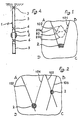
- Figs. 1 to 3 relate to the case where it is desired to develop a crack inside the contour A B C D of any kind, situated in any plane of a mass of solid material such as a solid mass or any block of rock.
- two holes 101.102 (Fig. 1) are drilled, in the plane P of the desired cut, or substantially in this plane. They are connected by an initial crack 2 and we proceed as indicated below to put them under pressure.
- the pressurization is done from the two holes, unless there has been sufficient communication between them, in which case it can be done from a single hole.
- the crack then develops by being strongly guided along the holes 101 and 102, because of the pressure existing in these holes, it develops faster along the latter than in the zone lying between them and therefore always tends to remain in the plane P even when the holes 101 and 102 are relatively distant from each other.
- the limit of the crack progression at a given time has been represented by a dashed line 20.
- these traces 20a and 20b correspond to a defective progression of the crack: the trace 20a convex in the direction of progression, that is to say towards the top of the figure may result from the interaction of two flow of fluid coming from holes 101 and 102 and coming to meet at approximately equal distance from these holes.
- the crack is likely to take the form of a fraction of cone limited by two generatrices corresponding to the two holes.
- the excessively concave line 20b is due to insufficient blowing of fluid at a certain distance from the holes.
- the crack can then take an aberrant orientation, in a helix for example, in the vicinity of each hole.
- the diagram in FIG. 2 comprises two sets of each two holes 102, 104 and 105, 106, with two initial crack initiators giving guidance which extends to a larger area than in the case of FIG. 1.
- Fig. 3 we assumed that we created a single initial crack 2 at the place where two holes 107 and 110 overlap or are very close to each other, the hole 110 extending beyond this place . This crack will then develop along hole 107 and on both sides, along hole 110. From the place where two other holes 108 and 109, also kept under pressure P2, intersect or are very close together of hole 110, the crack is guided by these holes 108 and 109 and finally the crack is strongly guided along all the holes and in the space between these holes, the progression being indicated by the dashed lines 21 to 24 The crack is therefore guided over a very large area with a very small number of holes.
- Each of the holes includes one of the means described below for exerting pressure on its walls, only one of the holes may include insufflation means in the initial crack 2 but all or part of the holes may include insufflation zones which only become active after the crack has passed through these areas.
- diagrams identical to those of FIGS. 1, 2 and 3 can be created in planes P overlapping inside the block or block, thus determining smaller blocks, all limited by substantially plane walls.
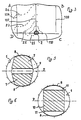
- Figs. 4 to 6 illustrate the various devices that can be fitted to each of the holes 1 with a pair of holes such as 101, 102 to pressurize them.
- Each of the holes includes at least one plug obstructing its free end (s). It can be very short such as 3.
- This plug can also be constituted by a transversely elastic pipe element 5, described below.
- the pressure P2 acting on the walls of the hole for guiding the crack can be exerted either uniformly over the entire perimeter of the hole, or mainly only on two opposite sectors of this perimeter, sectors arranged on either side of the plane P of the cut.
- this pressure can be equal to the insufflation pressure over the entire length of the hole but the insufflation fluid can be isolated from the crack developing along the hole by a cladding 4 so that the insufflation takes place only in the initial cracking zone and possibly in certain zones which one wishes to privilege.
- a pressure P2 pcur the guidance of the crack.
- FIGS. 5 and 6 representing the sections of the hole in the areas where such devices are installed.
- Fig. 5 there are shown two rigid support pieces 7 of the desired length, exerting on opposite sectors 8, the force transmitted to them by an inflatable piping element 9.
- the sectors 8 are, of course, on either side of the plan P.
- Fig. 6 there is a single rigid part 10 and two inflatable pipe elements 11 are supported on one side on this rigid part 10, and on the other hand on the opposite sectors 8.
- the pressurization of the blowing and guiding fluids can be carried out by numerous known means which are not described here.
- the blowing fluid under pressure either can be brought in from the outside through the plug (s) 3, 6 as well as the constant pressure zone from which it will remain isolated, or be supplied by the fluid initially placed in the hole and by the gas from the explosion of a slow explosive or powder, or any other means of generating pressurized gas. It may be necessary for this deflagration to occur in more than one time so as to produce at the beginning only a small quantity of gas, then in one or more subsequent sequences, at the moment when part of the insufflation fluids escapes to the outside, a higher amount of gas.
- the fluid in the inflatable pipe element (s) 5, 9, 11 can be pressurized either by a pressurized fluid supplied from the outside, or by another method such as deflagration, the main thing being that pressure is exerted on the walls of the hole before the crack develops along these walls.
Landscapes
- Engineering & Computer Science (AREA)
- Mining & Mineral Resources (AREA)
- Mechanical Engineering (AREA)
- Life Sciences & Earth Sciences (AREA)
- General Life Sciences & Earth Sciences (AREA)
- Geochemistry & Mineralogy (AREA)
- Geology (AREA)
- Drilling And Exploitation, And Mining Machines And Methods (AREA)
- Processing Of Stones Or Stones Resemblance Materials (AREA)
- Mechanical Treatment Of Semiconductor (AREA)
- Superconductors And Manufacturing Methods Therefor (AREA)
- Safety Valves (AREA)
- Polishing Bodies And Polishing Tools (AREA)
- Photoreceptors In Electrophotography (AREA)
- Control Of Vending Devices And Auxiliary Devices For Vending Devices (AREA)
- Manufacturing Of Magnetic Record Carriers (AREA)
Claims (7)
Priority Applications (1)
| Application Number | Priority Date | Filing Date | Title |
|---|---|---|---|
| AT84402210T ATE32367T1 (de) | 1983-11-07 | 1984-11-05 | Verfahren zum schneiden eines soliden kompakten materials. |
Applications Claiming Priority (2)
| Application Number | Priority Date | Filing Date | Title |
|---|---|---|---|
| FR8318060A FR2554384B1 (fr) | 1983-11-07 | 1983-11-07 | Procede de decoupage d'une masse de matiere solide compacte |
| FR8318060 | 1983-11-07 |
Publications (3)
| Publication Number | Publication Date |
|---|---|
| EP0145540A2 EP0145540A2 (de) | 1985-06-19 |
| EP0145540A3 EP0145540A3 (en) | 1985-07-10 |
| EP0145540B1 true EP0145540B1 (de) | 1988-02-03 |
Family
ID=9294075
Family Applications (1)
| Application Number | Title | Priority Date | Filing Date |
|---|---|---|---|
| EP84402210A Expired EP0145540B1 (de) | 1983-11-07 | 1984-11-05 | Verfahren zum Schneiden eines soliden kompakten Materials |
Country Status (7)
| Country | Link |
|---|---|
| EP (1) | EP0145540B1 (de) |
| AT (1) | ATE32367T1 (de) |
| DE (2) | DE3469202D1 (de) |
| ES (1) | ES8603773A1 (de) |
| FR (1) | FR2554384B1 (de) |
| NO (1) | NO163642C (de) |
| PT (1) | PT79468B (de) |
Families Citing this family (3)
| Publication number | Priority date | Publication date | Assignee | Title |
|---|---|---|---|---|
| DE102004013967A1 (de) | 2004-03-19 | 2005-10-06 | Basf Ag | Kühlung und Reinigung von Gasströmen |
| JP6017853B2 (ja) * | 2012-06-20 | 2016-11-02 | 株式会社熊谷組 | コンクリート破断方法 |
| CN113048845A (zh) * | 2021-02-05 | 2021-06-29 | 中国化工程重型机械化有限公司 | 一种液态co2相变水压爆破筒 |
Family Cites Families (10)
| Publication number | Priority date | Publication date | Assignee | Title |
|---|---|---|---|---|
| FR12434E (de) * | ||||
| FR405498A (fr) * | 1909-07-19 | 1909-12-31 | Adolphe Rossi | Procédé et outillage permettant le tranchage de la pierre dans la masse ou dans des blocs déjà extraits |
| GB399597A (en) * | 1932-06-20 | 1933-10-12 | James Tonge | Improvements in hydraulic presses for breaking down coal, rock and other substances in mining or quarrying operations |
| FR984105A (fr) * | 1949-02-10 | 1951-07-02 | Méthode de minage sans explosif | |
| GB743998A (en) * | 1953-01-28 | 1956-01-25 | Mini Of Fuel And Power | Improvements in or relating to coal mining |
| GB775342A (en) * | 1954-01-20 | 1957-05-22 | Ici Ltd | Improved method of blasting |
| US3507540A (en) * | 1968-04-05 | 1970-04-21 | Pan American Petroleum Corp | Method and apparatus for cutting large diameter bore holes |
| US3933205A (en) * | 1973-10-09 | 1976-01-20 | Othar Meade Kiel | Hydraulic fracturing process using reverse flow |
| CH590398A5 (de) * | 1974-04-25 | 1977-08-15 | Cerac Inst Sa | |
| US4393933A (en) * | 1980-06-02 | 1983-07-19 | Standard Oil Company (Indiana) | Determination of maximum fracture pressure |
-
1983
- 1983-11-07 FR FR8318060A patent/FR2554384B1/fr not_active Expired
-
1984
- 1984-11-05 DE DE8484402210T patent/DE3469202D1/de not_active Expired
- 1984-11-05 DE DE198484402210T patent/DE145540T1/de active Pending
- 1984-11-05 AT AT84402210T patent/ATE32367T1/de not_active IP Right Cessation
- 1984-11-05 EP EP84402210A patent/EP0145540B1/de not_active Expired
- 1984-11-06 NO NO844416A patent/NO163642C/no unknown
- 1984-11-07 PT PT79468A patent/PT79468B/pt unknown
- 1984-11-07 ES ES537474A patent/ES8603773A1/es not_active Expired
Also Published As
| Publication number | Publication date |
|---|---|
| NO163642C (no) | 1990-06-27 |
| DE145540T1 (de) | 1985-12-05 |
| EP0145540A3 (en) | 1985-07-10 |
| PT79468B (fr) | 1986-08-05 |
| ES537474A0 (es) | 1986-01-01 |
| NO163642B (no) | 1990-03-19 |
| EP0145540A2 (de) | 1985-06-19 |
| PT79468A (fr) | 1984-12-01 |
| FR2554384B1 (fr) | 1987-04-03 |
| FR2554384A1 (fr) | 1985-05-10 |
| NO844416L (no) | 1985-05-08 |
| ES8603773A1 (es) | 1986-01-01 |
| ATE32367T1 (de) | 1988-02-15 |
| DE3469202D1 (en) | 1988-03-10 |
Similar Documents
| Publication | Publication Date | Title |
|---|---|---|
| CN100572747C (zh) | 不牢固和脆弱粘结的沉积物中的竖直液压裂缝的多方位控制 | |
| EP0114016A1 (de) | Bohrmeissel für kombiniertes Dreh- und Strahlbohren | |
| FR2461804A1 (fr) | Outil de forage pour appareil a percussion | |
| WO2000058601A1 (fr) | Dispositif d'obturation d'un puits de forage | |
| MC721A1 (fr) | Dispositif de tirant destiné à être ancré dans le sol | |
| FR2619154A1 (fr) | Methode et dispositif hydrauliques ameliores de penetration de puits | |
| CA2033357A1 (fr) | Methode et dispositif pour stimuler une zone souterraine par injection controlee de fluide provenant d'une zone voisine que l'on relie a la premiere par un drain traversant une couche intermediaire peu permeable | |
| EP0145540A2 (de) | Verfahren zum Schneiden eines soliden kompakten Materials | |
| SU1550174A1 (ru) | Способ дегазации горного массива | |
| EP0457653B1 (de) | Sicherheitshülse und Vorrichtung für Bohrlöcher, insbesondere für ein unterirdischen unter Druck stehenden Flüssigkeitsbehälter | |
| EP2908316B1 (de) | Verfahren und Anlage zum Schneiden eines Massivbauteils aus Stahlbeton | |
| FR2483005A1 (fr) | Procede pour fracturer hydrauliquement une formation geologique selon une direction predeterminee | |
| FR2611239A1 (fr) | Element moteur | |
| US4394051A (en) | Method of hydrospalling | |
| NO180653B (no) | Fremgangsmåte for forbedret ytelse av gruspakkete brönner | |
| US3507540A (en) | Method and apparatus for cutting large diameter bore holes | |
| FR2610652A1 (fr) | Procede de renforcement d'un pieu tubulaire battu, pieu obtenu par ce procede, dispositif pour mettre en oeuvre le procede | |
| RU2601341C1 (ru) | Способ формирования проводящих трещин в продуктивной породе за обсадной колонной скважины | |
| EP3221553B1 (de) | Verfahren zur hydraulik stimulierung und eine entsprechende vorrichtung | |
| FR2595406A1 (fr) | Procede et dispositif pour effectuer un renforcement de roche par fil metallique | |
| US703302A (en) | Method of raising sheets of stone. | |
| SU1749454A1 (ru) | Способ добычи блочного камн | |
| SU1113570A1 (ru) | Способ дегазации угольных пластов | |
| FR2756853A1 (fr) | Colonne de materiau dans le sol, destinee a encaisser des charges ou a compacter le sol, procede et appareil pour sa realisation | |
| SU1384726A1 (ru) | Способ разобщени интервалов гидрообработки массива горных пород |
Legal Events
| Date | Code | Title | Description |
|---|---|---|---|
| PUAI | Public reference made under article 153(3) epc to a published international application that has entered the european phase |
Free format text: ORIGINAL CODE: 0009012 |
|
| PUAL | Search report despatched |
Free format text: ORIGINAL CODE: 0009013 |
|
| AK | Designated contracting states |
Designated state(s): AT BE CH DE FR GB IT LI LU NL SE |
|
| AK | Designated contracting states |
Designated state(s): AT BE CH DE FR GB IT LI LU NL SE |
|
| ITCL | It: translation for ep claims filed |
Representative=s name: MODIANO & ASSOCIATI S.R.L. |
|
| RBV | Designated contracting states (corrected) |
Designated state(s): AT BE DE GB IT SE |
|
| 17P | Request for examination filed |
Effective date: 19850712 |
|
| DET | De: translation of patent claims | ||
| TCAT | At: translation of patent claims filed | ||
| 17Q | First examination report despatched |
Effective date: 19861021 |
|
| GRAA | (expected) grant |
Free format text: ORIGINAL CODE: 0009210 |
|
| AK | Designated contracting states |
Kind code of ref document: B1 Designated state(s): AT BE DE GB IT SE |
|
| REF | Corresponds to: |
Ref document number: 32367 Country of ref document: AT Date of ref document: 19880215 Kind code of ref document: T |
|
| REF | Corresponds to: |
Ref document number: 3469202 Country of ref document: DE Date of ref document: 19880310 |
|
| ITF | It: translation for a ep patent filed | ||
| GBV | Gb: ep patent (uk) treated as always having been void in accordance with gb section 77(7)/1977 [no translation filed] | ||
| PG25 | Lapsed in a contracting state [announced via postgrant information from national office to epo] |
Ref country code: GB Free format text: LAPSE BECAUSE OF NON-PAYMENT OF DUE FEES Effective date: 19881123 |
|
| PLBE | No opposition filed within time limit |
Free format text: ORIGINAL CODE: 0009261 |
|
| STAA | Information on the status of an ep patent application or granted ep patent |
Free format text: STATUS: NO OPPOSITION FILED WITHIN TIME LIMIT |
|
| 26N | No opposition filed | ||
| PGFP | Annual fee paid to national office [announced via postgrant information from national office to epo] |
Ref country code: DE Payment date: 19891110 Year of fee payment: 6 |
|
| PGFP | Annual fee paid to national office [announced via postgrant information from national office to epo] |
Ref country code: AT Payment date: 19891114 Year of fee payment: 6 |
|
| PGFP | Annual fee paid to national office [announced via postgrant information from national office to epo] |
Ref country code: BE Payment date: 19891204 Year of fee payment: 6 |
|
| PG25 | Lapsed in a contracting state [announced via postgrant information from national office to epo] |
Ref country code: AT Effective date: 19901105 |
|
| PG25 | Lapsed in a contracting state [announced via postgrant information from national office to epo] |
Ref country code: BE Effective date: 19901130 |
|
| BERE | Be: lapsed |
Owner name: VINCENT ETIENNE Effective date: 19901130 |
|
| PG25 | Lapsed in a contracting state [announced via postgrant information from national office to epo] |
Ref country code: DE Effective date: 19910801 |
|
| PGFP | Annual fee paid to national office [announced via postgrant information from national office to epo] |
Ref country code: SE Payment date: 19911121 Year of fee payment: 8 |
|
| ITTA | It: last paid annual fee | ||
| PG25 | Lapsed in a contracting state [announced via postgrant information from national office to epo] |
Ref country code: SE Effective date: 19921106 |
|
| EUG | Se: european patent has lapsed |
Ref document number: 84402210.3 Effective date: 19930610 |