EP0145557A2 - Wellenlötverfahren unter Verwendung einer rapillaren Struktur zur Aufnahme der Lötmittels - Google Patents
Wellenlötverfahren unter Verwendung einer rapillaren Struktur zur Aufnahme der Lötmittels Download PDFInfo
- Publication number
- EP0145557A2 EP0145557A2 EP84402304A EP84402304A EP0145557A2 EP 0145557 A2 EP0145557 A2 EP 0145557A2 EP 84402304 A EP84402304 A EP 84402304A EP 84402304 A EP84402304 A EP 84402304A EP 0145557 A2 EP0145557 A2 EP 0145557A2
- Authority
- EP
- European Patent Office
- Prior art keywords
- component
- substrate
- capillary
- solder
- connection pads
- Prior art date
- Legal status (The legal status is an assumption and is not a legal conclusion. Google has not performed a legal analysis and makes no representation as to the accuracy of the status listed.)
- Granted
Links
Images


Classifications
-
- B—PERFORMING OPERATIONS; TRANSPORTING
- B23—MACHINE TOOLS; METAL-WORKING NOT OTHERWISE PROVIDED FOR
- B23K—SOLDERING OR UNSOLDERING; WELDING; CLADDING OR PLATING BY SOLDERING OR WELDING; CUTTING BY APPLYING HEAT LOCALLY, e.g. FLAME CUTTING; WORKING BY LASER BEAM
- B23K1/00—Soldering, e.g. brazing, or unsoldering
- B23K1/20—Preliminary treatment of work or areas to be soldered, e.g. in respect of a galvanic coating
-
- H—ELECTRICITY
- H05—ELECTRIC TECHNIQUES NOT OTHERWISE PROVIDED FOR
- H05K—PRINTED CIRCUITS; CASINGS OR CONSTRUCTIONAL DETAILS OF ELECTRIC APPARATUS; MANUFACTURE OF ASSEMBLAGES OF ELECTRICAL COMPONENTS
- H05K3/00—Apparatus or processes for manufacturing printed circuits
- H05K3/30—Assembling printed circuits with electric components, e.g. with resistors
- H05K3/32—Assembling printed circuits with electric components, e.g. with resistors electrically connecting electric components or wires to printed circuits
- H05K3/34—Assembling printed circuits with electric components, e.g. with resistors electrically connecting electric components or wires to printed circuits by soldering
- H05K3/341—Surface mounted components
- H05K3/3421—Leaded components
- H05K3/3426—Leaded components characterised by the leads
-
- H—ELECTRICITY
- H05—ELECTRIC TECHNIQUES NOT OTHERWISE PROVIDED FOR
- H05K—PRINTED CIRCUITS; CASINGS OR CONSTRUCTIONAL DETAILS OF ELECTRIC APPARATUS; MANUFACTURE OF ASSEMBLAGES OF ELECTRICAL COMPONENTS
- H05K3/00—Apparatus or processes for manufacturing printed circuits
- H05K3/30—Assembling printed circuits with electric components, e.g. with resistors
- H05K3/32—Assembling printed circuits with electric components, e.g. with resistors electrically connecting electric components or wires to printed circuits
- H05K3/34—Assembling printed circuits with electric components, e.g. with resistors electrically connecting electric components or wires to printed circuits by soldering
- H05K3/341—Surface mounted components
- H05K3/3431—Leadless components
- H05K3/3442—Leadless components having edge contacts, e.g. leadless chip capacitors, chip carriers
-
- H—ELECTRICITY
- H05—ELECTRIC TECHNIQUES NOT OTHERWISE PROVIDED FOR
- H05K—PRINTED CIRCUITS; CASINGS OR CONSTRUCTIONAL DETAILS OF ELECTRIC APPARATUS; MANUFACTURE OF ASSEMBLAGES OF ELECTRICAL COMPONENTS
- H05K3/00—Apparatus or processes for manufacturing printed circuits
- H05K3/30—Assembling printed circuits with electric components, e.g. with resistors
- H05K3/32—Assembling printed circuits with electric components, e.g. with resistors electrically connecting electric components or wires to printed circuits
- H05K3/34—Assembling printed circuits with electric components, e.g. with resistors electrically connecting electric components or wires to printed circuits by soldering
- H05K3/3465—Application of solder
- H05K3/3468—Application of molten solder, e.g. dip soldering
-
- B—PERFORMING OPERATIONS; TRANSPORTING
- B23—MACHINE TOOLS; METAL-WORKING NOT OTHERWISE PROVIDED FOR
- B23K—SOLDERING OR UNSOLDERING; WELDING; CLADDING OR PLATING BY SOLDERING OR WELDING; CUTTING BY APPLYING HEAT LOCALLY, e.g. FLAME CUTTING; WORKING BY LASER BEAM
- B23K2101/00—Articles made by soldering, welding or cutting
- B23K2101/36—Electric or electronic devices
- B23K2101/40—Semiconductor devices
-
- H—ELECTRICITY
- H05—ELECTRIC TECHNIQUES NOT OTHERWISE PROVIDED FOR
- H05K—PRINTED CIRCUITS; CASINGS OR CONSTRUCTIONAL DETAILS OF ELECTRIC APPARATUS; MANUFACTURE OF ASSEMBLAGES OF ELECTRICAL COMPONENTS
- H05K2201/00—Indexing scheme relating to printed circuits covered by H05K1/00
- H05K2201/09—Shape and layout
- H05K2201/09145—Edge details
- H05K2201/09181—Notches in edge pads
-
- H—ELECTRICITY
- H05—ELECTRIC TECHNIQUES NOT OTHERWISE PROVIDED FOR
- H05K—PRINTED CIRCUITS; CASINGS OR CONSTRUCTIONAL DETAILS OF ELECTRIC APPARATUS; MANUFACTURE OF ASSEMBLAGES OF ELECTRICAL COMPONENTS
- H05K2201/00—Indexing scheme relating to printed circuits covered by H05K1/00
- H05K2201/09—Shape and layout
- H05K2201/09209—Shape and layout details of conductors
- H05K2201/09372—Pads and lands
- H05K2201/09381—Shape of non-curved single flat metallic pad, land or exposed part thereof; Shape of electrode of leadless component
-
- H—ELECTRICITY
- H05—ELECTRIC TECHNIQUES NOT OTHERWISE PROVIDED FOR
- H05K—PRINTED CIRCUITS; CASINGS OR CONSTRUCTIONAL DETAILS OF ELECTRIC APPARATUS; MANUFACTURE OF ASSEMBLAGES OF ELECTRICAL COMPONENTS
- H05K2201/00—Indexing scheme relating to printed circuits covered by H05K1/00
- H05K2201/10—Details of components or other objects attached to or integrated in a printed circuit board
- H05K2201/10431—Details of mounted components
- H05K2201/10507—Involving several components
- H05K2201/10522—Adjacent components
-
- H—ELECTRICITY
- H05—ELECTRIC TECHNIQUES NOT OTHERWISE PROVIDED FOR
- H05K—PRINTED CIRCUITS; CASINGS OR CONSTRUCTIONAL DETAILS OF ELECTRIC APPARATUS; MANUFACTURE OF ASSEMBLAGES OF ELECTRICAL COMPONENTS
- H05K2201/00—Indexing scheme relating to printed circuits covered by H05K1/00
- H05K2201/10—Details of components or other objects attached to or integrated in a printed circuit board
- H05K2201/10613—Details of electrical connections of non-printed components, e.g. special leads
- H05K2201/10621—Components characterised by their electrical contacts
- H05K2201/10727—Leadless chip carrier [LCC], e.g. chip-modules for cards
-
- H—ELECTRICITY
- H05—ELECTRIC TECHNIQUES NOT OTHERWISE PROVIDED FOR
- H05K—PRINTED CIRCUITS; CASINGS OR CONSTRUCTIONAL DETAILS OF ELECTRIC APPARATUS; MANUFACTURE OF ASSEMBLAGES OF ELECTRICAL COMPONENTS
- H05K2201/00—Indexing scheme relating to printed circuits covered by H05K1/00
- H05K2201/10—Details of components or other objects attached to or integrated in a printed circuit board
- H05K2201/10613—Details of electrical connections of non-printed components, e.g. special leads
- H05K2201/10742—Details of leads
- H05K2201/10886—Other details
- H05K2201/10946—Leads attached onto leadless component after manufacturing the component
-
- H—ELECTRICITY
- H05—ELECTRIC TECHNIQUES NOT OTHERWISE PROVIDED FOR
- H05K—PRINTED CIRCUITS; CASINGS OR CONSTRUCTIONAL DETAILS OF ELECTRIC APPARATUS; MANUFACTURE OF ASSEMBLAGES OF ELECTRICAL COMPONENTS
- H05K2203/00—Indexing scheme relating to apparatus or processes for manufacturing printed circuits covered by H05K3/00
- H05K2203/04—Soldering or other types of metallurgic bonding
- H05K2203/046—Means for drawing solder, e.g. for removing excess solder from pads
-
- H—ELECTRICITY
- H05—ELECTRIC TECHNIQUES NOT OTHERWISE PROVIDED FOR
- H05K—PRINTED CIRCUITS; CASINGS OR CONSTRUCTIONAL DETAILS OF ELECTRIC APPARATUS; MANUFACTURE OF ASSEMBLAGES OF ELECTRICAL COMPONENTS
- H05K2203/00—Indexing scheme relating to apparatus or processes for manufacturing printed circuits covered by H05K3/00
- H05K2203/15—Position of the PCB during processing
- H05K2203/1581—Treating the backside of the PCB, e.g. for heating during soldering or providing a liquid coating on the backside
-
- H—ELECTRICITY
- H05—ELECTRIC TECHNIQUES NOT OTHERWISE PROVIDED FOR
- H05K—PRINTED CIRCUITS; CASINGS OR CONSTRUCTIONAL DETAILS OF ELECTRIC APPARATUS; MANUFACTURE OF ASSEMBLAGES OF ELECTRICAL COMPONENTS
- H05K3/00—Apparatus or processes for manufacturing printed circuits
- H05K3/30—Assembling printed circuits with electric components, e.g. with resistors
- H05K3/303—Assembling printed circuits with electric components, e.g. with resistors with surface mounted components
- H05K3/305—Affixing by adhesive
-
- H—ELECTRICITY
- H05—ELECTRIC TECHNIQUES NOT OTHERWISE PROVIDED FOR
- H05K—PRINTED CIRCUITS; CASINGS OR CONSTRUCTIONAL DETAILS OF ELECTRIC APPARATUS; MANUFACTURE OF ASSEMBLAGES OF ELECTRICAL COMPONENTS
- H05K3/00—Apparatus or processes for manufacturing printed circuits
- H05K3/30—Assembling printed circuits with electric components, e.g. with resistors
- H05K3/32—Assembling printed circuits with electric components, e.g. with resistors electrically connecting electric components or wires to printed circuits
- H05K3/34—Assembling printed circuits with electric components, e.g. with resistors electrically connecting electric components or wires to printed circuits by soldering
- H05K3/3405—Edge mounted components, e.g. terminals
-
- Y—GENERAL TAGGING OF NEW TECHNOLOGICAL DEVELOPMENTS; GENERAL TAGGING OF CROSS-SECTIONAL TECHNOLOGIES SPANNING OVER SEVERAL SECTIONS OF THE IPC; TECHNICAL SUBJECTS COVERED BY FORMER USPC CROSS-REFERENCE ART COLLECTIONS [XRACs] AND DIGESTS
- Y02—TECHNOLOGIES OR APPLICATIONS FOR MITIGATION OR ADAPTATION AGAINST CLIMATE CHANGE
- Y02P—CLIMATE CHANGE MITIGATION TECHNOLOGIES IN THE PRODUCTION OR PROCESSING OF GOODS
- Y02P70/00—Climate change mitigation technologies in the production process for final industrial or consumer products
- Y02P70/50—Manufacturing or production processes characterised by the final manufactured product
Definitions
- the invention relates to a wave soldering method for soldering, on a printed circuit board, components whose connection pins do not pass through the board.
- the invention also relates to capillary sensors implementing this method.
- connection of a component to a printed circuit board is made using pins belonging to the component, passing through the printed circuit board by connection holes, and by soldering the pins to pads. connection located on the opposite side of the card.
- the soldering operation is carried out by passing the card over a wave of molten solder, the face of the card carrying the connection pads coming into contact, during this passage, with the solder wave.
- the pins of the components do not pass through the printed circuit board.
- the components have connection pads which are simply brought into contact with connection pads on the printed circuit board and to which they are then soldered.
- This soldering can also be carried out by passing over a solder wave.
- the components are first placed in position on the card and immobilized, the connection pads of the components being in contact with the connection pads of the card.
- the card is then passed over the solder wave, the face carrying the connection pads as well as the components coming into contact with the solder wave.
- each component therefore bathes in the molten solder bath.
- the face of the component which attacks the solder wave is, in principle, in full contact with the solder.
- soldering The metallized parts of this face are wetted by soldering and the soldering of the connection pads of this face of the component with the pads of the card can be done.
- the card due to the temperature of the solder bath, the card must pass at a sufficient speed, to avoid the heating of the components. Therefore, the flow of the solder fluid on the sides and on the rear face of each component is such that some parts of the component may not be in contact with the solder. The soldering of the connection pads may not be ensured.
- the object of the invention is to provide a method for ensuring soldering of all the connection pads of a component on the connection pads of a substrate. It also provides a capillary solder sensor allowing this method to be implemented.
- the invention also relates to a capillary solder sensor enabling this method to be implemented.
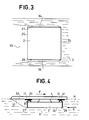
- FIG. 1 there is a printed circuit board 1 equipped with a component 2.
- a wave of molten brazing alloy 3 is produced by an alloy flow 30 channeled by two parts 31 and 32. This wave touches a plane P.
- the card 1 is placed on a transfer device, not shown and known in the art. It is moved in the direction indicated by the arrow F with its side 10 to be welded located in the P.
- Card 1 has on its face 10 not shown printed circuits and connection pads 11 and 12.
- Component 2 is bonded to face 10 of card 1 by a boss 22.
- Component 2 also has, on its face 26, connection pads such as 20 and 21 which are brought into contact (or in the vicinity) of the connection pads 11 and 12 of the card 1.
- the card 1 passes over the solder wave 3, it scans the surface of the card.
- the solder wets the metal parts with which it comes into contact and the metal parts, such as connection pads, are soldered.
- the component is immersed in the molten solder during the movement of the card. It is therefore advantageous for this displacement to be sufficiently rapid. It then turns out, due to the flow of the solder fluid around the component 2, that parts of the component are not brought into contact with the solder.
- FIG. 2 it can be seen that the front face 23 of the component as well as the connection pads 12 and 21 are immersed in the solder, the same is true of the face 24 of the component.
- connection pads 11 and 20 cannot therefore be soldered. Similarly as can be seen in Figure 3, it can occur an absence of solder in the zone 34 on either side of the lateral faces 27 and 37 of the component.
- the invention before the step of passing the card 2 over the solder wave, provides for placing capillary solder sensors connecting each pad, such as 20, to the face 24 of the component.
- the solder by sweeping the face 24 of the component comes into contact with the capillary sensor, wets it, and progresses by capillarity towards the connection pads.
- FIG 4 there is shown a capillary sensor 27 connecting the connection pad 20 to the face 24 of the component.
- a sensor 28 although it is not essential, connects the connection pad 21 to the face 24.
- the card 1 moving according to the arrow F, in relative movement, the solder moves relative to the component according to arrow A.
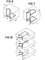
- a capillary sensor can be produced, as shown in FIG. 6, in the form of a groove made along the edge of the component from the connection pad 20. This groove is then metallized using a material having wetting properties with respect to the brazing alloy.
- the advantage of providing the capillary sensor, in the form of a groove, is to increase the surface of the capillary sensor.
- the metallized groove 27 is extended on the face 24, by a metallized area 29 of the same type as the groove. The capture of the solder when passing over the solder wave is thus improved.
- a capillary sensor according to the invention has been shown in the form of a jumper 27 plugged in on the edge of the component 2, exerting a slight pressure on the face 24 and the connection pad 20.
- component assembly 2, jumper 27, stud connection 20 and connection pad 11 are coated with solder.
- the invention also makes it possible to solve the problems of connection of components with several layers.
- the component of FIG. 10 has three layers 2, 4 and 6.
- Layer 2 carries on its face 26, a connection pad 20.
- Layer 4 has a connection 42 of the internal circuit to the component.
- a groove 27 leading to the stud 20 is formed in the edge of the layer 2 and is metallized.
- metallized grooves 41 and 61 are formed in correspondence with the groove 27 in layers 4 and 6.
- metallized bases 29, 40, 43 and 60 are produced on either side of layers 2, 4 , 6, around the grooves.
- a metallized base 62 is also produced on the upper face of the layer 6. The different layers are then stacked, pressed and glued one against the other.
- the bases 29, 40, 43 and 63 provide metallic continuity of the groove to improve the flow of the solder along the groove during the transition to the solder wave.
- the capillary sensor can also be supported by another part than the component itself.
- the capillary sensor on the face 10 of the printed circuit board 1, there are elements specially designed for this use such as the element 50.
- the element 50 On the element 50 is deposited a metallized strip 51, 52, 53 connecting the top of the element 50 to the connection pad 11 of the card.
- the height h of the element 50 is such that depending on the wave, the height of the components and the position of the element 50 relative to the components, the part 51 of metallized strip is reached by the solder wave .
- several capillary sensors can be provided on an element 50.
- an element 50 can serve several components.
Landscapes
- Engineering & Computer Science (AREA)
- Manufacturing & Machinery (AREA)
- Microelectronics & Electronic Packaging (AREA)
- Mechanical Engineering (AREA)
- Electric Connection Of Electric Components To Printed Circuits (AREA)
Applications Claiming Priority (2)
| Application Number | Priority Date | Filing Date | Title |
|---|---|---|---|
| FR8318128 | 1983-11-15 | ||
| FR8318128A FR2555010B1 (fr) | 1983-11-15 | 1983-11-15 | Procede de brasage a la vague et capteur capillaire de brasure mettant en oeuvre ce procede |
Publications (3)
| Publication Number | Publication Date |
|---|---|
| EP0145557A2 true EP0145557A2 (de) | 1985-06-19 |
| EP0145557A3 EP0145557A3 (en) | 1985-07-10 |
| EP0145557B1 EP0145557B1 (de) | 1989-07-26 |
Family
ID=9294121
Family Applications (1)
| Application Number | Title | Priority Date | Filing Date |
|---|---|---|---|
| EP84402304A Expired EP0145557B1 (de) | 1983-11-15 | 1984-11-13 | Wellenlötverfahren unter Verwendung einer rapillaren Struktur zur Aufnahme der Lötmittels |
Country Status (3)
| Country | Link |
|---|---|
| EP (1) | EP0145557B1 (de) |
| DE (1) | DE3479178D1 (de) |
| FR (1) | FR2555010B1 (de) |
Cited By (3)
| Publication number | Priority date | Publication date | Assignee | Title |
|---|---|---|---|---|
| EP0210560A3 (de) * | 1985-07-27 | 1987-05-27 | GRUNDIG E.M.V. Elektro-Mechanische Versuchsanstalt Max Grundig holländ. Stiftung & Co. KG. | Verfahren zum Einlöten einer integrierten Schaltung in eine Leiterplatte |
| FR2613898A1 (fr) * | 1987-04-13 | 1988-10-14 | Siame Electronique Sa | Procede de soudage de composants pour montage en surface (cms) sur circuit imprime |
| EP0245188A3 (de) * | 1986-04-28 | 1989-12-06 | Société Talco | Hartlötverfahren von Oberflächenbauelementen auf einer gedruckten Leiterplatte |
Family Cites Families (4)
| Publication number | Priority date | Publication date | Assignee | Title |
|---|---|---|---|---|
| GB811509A (en) * | 1954-11-22 | 1959-04-08 | Ibm | Improvements relating to printed circuit connections |
| FR1369630A (fr) * | 1963-09-06 | 1964-08-14 | Atomic Energy Authority Uk | Système de brasure pour joints |
| JPS5724775U (de) * | 1980-07-17 | 1982-02-08 | ||
| DE3231056A1 (de) * | 1982-08-20 | 1984-02-23 | Siemens AG, 1000 Berlin und 8000 München | Verfahren zum aufbringen von unbedrahteten bauelementen auf leiterplatten |
-
1983
- 1983-11-15 FR FR8318128A patent/FR2555010B1/fr not_active Expired
-
1984
- 1984-11-13 EP EP84402304A patent/EP0145557B1/de not_active Expired
- 1984-11-13 DE DE8484402304T patent/DE3479178D1/de not_active Expired
Cited By (3)
| Publication number | Priority date | Publication date | Assignee | Title |
|---|---|---|---|---|
| EP0210560A3 (de) * | 1985-07-27 | 1987-05-27 | GRUNDIG E.M.V. Elektro-Mechanische Versuchsanstalt Max Grundig holländ. Stiftung & Co. KG. | Verfahren zum Einlöten einer integrierten Schaltung in eine Leiterplatte |
| EP0245188A3 (de) * | 1986-04-28 | 1989-12-06 | Société Talco | Hartlötverfahren von Oberflächenbauelementen auf einer gedruckten Leiterplatte |
| FR2613898A1 (fr) * | 1987-04-13 | 1988-10-14 | Siame Electronique Sa | Procede de soudage de composants pour montage en surface (cms) sur circuit imprime |
Also Published As
| Publication number | Publication date |
|---|---|
| FR2555010A1 (fr) | 1985-05-17 |
| EP0145557B1 (de) | 1989-07-26 |
| DE3479178D1 (en) | 1989-08-31 |
| FR2555010B1 (fr) | 1986-08-29 |
| EP0145557A3 (en) | 1985-07-10 |
Similar Documents
| Publication | Publication Date | Title |
|---|---|---|
| FR2769390A1 (fr) | Procede de fabrication de cartes a puce aptes a assurer un fonctionnement a contact et sans contact, et de cartes a puce sans contact | |
| KR100959847B1 (ko) | 전자 장치 및 전자 장치의 제조 방법 | |
| FR2591815A1 (fr) | Structure d'interconnexion de plot de soudage | |
| FR2634616A1 (fr) | Procede de montage de micro-composants electroniques sur un support et produit realisable par le procede | |
| FR2550905A1 (fr) | Carte de circuit imprime | |
| EP0717442B1 (de) | Träger für integrierten Schaltkreis zur Kontaktierung eines anderen Trägers mittels Kontaktkugeln | |
| FR2761527A1 (fr) | Procede de fabrication de carte sans contact avec connexion d'antenne par fils soudes | |
| FR2541044A1 (fr) | Procede de montage d'une plaquette de circuit integre sur un substrat | |
| EP0145557B1 (de) | Wellenlötverfahren unter Verwendung einer rapillaren Struktur zur Aufnahme der Lötmittels | |
| EP0112760B1 (de) | Mikrogehäuse für die Verkapselung eines elektronischen Bauelementes mit einer Vielzahl umgebogener Leiter | |
| JP4018702B2 (ja) | 磁気ヘッドアッセンブリ | |
| FR2540328A1 (de) | ||
| EP0221809B1 (de) | Hybridschaltung und Verfahren zum Herstellen einer solchen Schaltung | |
| EP0895627B1 (de) | Elektronische baugruppe mit einer an einer spule verbundenen elektronischen einheit | |
| EP1350418A1 (de) | Verfahren zur herstellung einer verbindung in mehrschichtigen leiterplatten | |
| EP4293569B1 (de) | Inlay für ein elektronisches dokument, verfahren zur herstellung eines elektronischen dokuments mit einem solchen inlay und dieses elektronische dokument | |
| FR2550906A1 (fr) | Carte de circuit imprime a couches multiples et son procede de fabrication | |
| FR2711830A1 (fr) | Assemblage patin de vol/bras-ressort à plots de soudures composités et procédé de réalisation. | |
| CH643089A5 (en) | Method of mounting an integrated circuit board on a substrate | |
| FR2693339A1 (fr) | Procédé de liaison et de fixation de composants à broches sur un circuit imprimé souple, et circuit ainsi obtenu. | |
| FR3145834A1 (fr) | Composant de liaison de signaux de boîtier de semi-conducteur de puissance et module à semi-conducteur | |
| FR2817398A1 (fr) | Boitier en film ultra-mince | |
| FR2588124A1 (fr) | Procede de connexion d'un circuit electronique sur un cable connecteur plat et souple | |
| EP0901165A1 (de) | Gehäuse für integrierte Schaltung und Verfahren zum Montieren einer integrierten Schaltung | |
| FR2691293A1 (fr) | Système de liaison électrique notamment pour circuits hybrides ou autres. |
Legal Events
| Date | Code | Title | Description |
|---|---|---|---|
| PUAI | Public reference made under article 153(3) epc to a published international application that has entered the european phase |
Free format text: ORIGINAL CODE: 0009012 |
|
| PUAL | Search report despatched |
Free format text: ORIGINAL CODE: 0009013 |
|
| AK | Designated contracting states |
Designated state(s): DE GB IT NL |
|
| AK | Designated contracting states |
Designated state(s): DE GB IT NL |
|
| 17P | Request for examination filed |
Effective date: 19851114 |
|
| 17Q | First examination report despatched |
Effective date: 19871021 |
|
| RAP3 | Party data changed (applicant data changed or rights of an application transferred) |
Owner name: THOMSON-CSF |
|
| GRAA | (expected) grant |
Free format text: ORIGINAL CODE: 0009210 |
|
| AK | Designated contracting states |
Kind code of ref document: B1 Designated state(s): DE GB IT NL |
|
| ITF | It: translation for a ep patent filed | ||
| REF | Corresponds to: |
Ref document number: 3479178 Country of ref document: DE Date of ref document: 19890831 |
|
| GBT | Gb: translation of ep patent filed (gb section 77(6)(a)/1977) | ||
| PLBE | No opposition filed within time limit |
Free format text: ORIGINAL CODE: 0009261 |
|
| STAA | Information on the status of an ep patent application or granted ep patent |
Free format text: STATUS: NO OPPOSITION FILED WITHIN TIME LIMIT |
|
| 26N | No opposition filed | ||
| PGFP | Annual fee paid to national office [announced via postgrant information from national office to epo] |
Ref country code: DE Payment date: 19921009 Year of fee payment: 9 |
|
| PGFP | Annual fee paid to national office [announced via postgrant information from national office to epo] |
Ref country code: GB Payment date: 19921014 Year of fee payment: 9 |
|
| ITTA | It: last paid annual fee | ||
| PGFP | Annual fee paid to national office [announced via postgrant information from national office to epo] |
Ref country code: NL Payment date: 19921130 Year of fee payment: 9 |
|
| PG25 | Lapsed in a contracting state [announced via postgrant information from national office to epo] |
Ref country code: GB Effective date: 19931113 |
|
| PG25 | Lapsed in a contracting state [announced via postgrant information from national office to epo] |
Ref country code: NL Effective date: 19940601 |
|
| GBPC | Gb: european patent ceased through non-payment of renewal fee |
Effective date: 19931113 |
|
| NLV4 | Nl: lapsed or anulled due to non-payment of the annual fee | ||
| PG25 | Lapsed in a contracting state [announced via postgrant information from national office to epo] |
Ref country code: DE Effective date: 19940802 |