EP0145559A2 - Mindestens eine thermische Zelle enthaltende Vorrichtung und ihre Verwendung als modulierbarer Energiegenerator - Google Patents
Mindestens eine thermische Zelle enthaltende Vorrichtung und ihre Verwendung als modulierbarer Energiegenerator Download PDFInfo
- Publication number
- EP0145559A2 EP0145559A2 EP84402315A EP84402315A EP0145559A2 EP 0145559 A2 EP0145559 A2 EP 0145559A2 EP 84402315 A EP84402315 A EP 84402315A EP 84402315 A EP84402315 A EP 84402315A EP 0145559 A2 EP0145559 A2 EP 0145559A2
- Authority
- EP
- European Patent Office
- Prior art keywords
- thermal
- battery
- electrical device
- cell
- switch
- Prior art date
- Legal status (The legal status is an assumption and is not a legal conclusion. Google has not performed a legal analysis and makes no representation as to the accuracy of the status listed.)
- Granted
Links
Images
Classifications
-
- H—ELECTRICITY
- H01—ELECTRIC ELEMENTS
- H01M—PROCESSES OR MEANS, e.g. BATTERIES, FOR THE DIRECT CONVERSION OF CHEMICAL ENERGY INTO ELECTRICAL ENERGY
- H01M6/00—Primary cells; Manufacture thereof
- H01M6/50—Methods or arrangements for servicing or maintenance, e.g. for maintaining operating temperature
- H01M6/5011—Methods or arrangements for servicing or maintenance, e.g. for maintaining operating temperature for several cells simultaneously or successively
-
- H—ELECTRICITY
- H01—ELECTRIC ELEMENTS
- H01M—PROCESSES OR MEANS, e.g. BATTERIES, FOR THE DIRECT CONVERSION OF CHEMICAL ENERGY INTO ELECTRICAL ENERGY
- H01M50/00—Constructional details or processes of manufacture of the non-active parts of electrochemical cells other than fuel cells, e.g. hybrid cells
- H01M50/50—Current conducting connections for cells or batteries
- H01M50/572—Means for preventing undesired use or discharge
- H01M50/574—Devices or arrangements for the interruption of current
- H01M50/581—Devices or arrangements for the interruption of current in response to temperature
-
- H—ELECTRICITY
- H01—ELECTRIC ELEMENTS
- H01M—PROCESSES OR MEANS, e.g. BATTERIES, FOR THE DIRECT CONVERSION OF CHEMICAL ENERGY INTO ELECTRICAL ENERGY
- H01M6/00—Primary cells; Manufacture thereof
- H01M6/30—Deferred-action cells
- H01M6/36—Deferred-action cells containing electrolyte and made operational by physical means, e.g. thermal cells
-
- H—ELECTRICITY
- H01—ELECTRIC ELEMENTS
- H01M—PROCESSES OR MEANS, e.g. BATTERIES, FOR THE DIRECT CONVERSION OF CHEMICAL ENERGY INTO ELECTRICAL ENERGY
- H01M6/00—Primary cells; Manufacture thereof
- H01M6/50—Methods or arrangements for servicing or maintenance, e.g. for maintaining operating temperature
-
- H—ELECTRICITY
- H01—ELECTRIC ELEMENTS
- H01M—PROCESSES OR MEANS, e.g. BATTERIES, FOR THE DIRECT CONVERSION OF CHEMICAL ENERGY INTO ELECTRICAL ENERGY
- H01M2200/00—Safety devices for primary or secondary batteries
- H01M2200/10—Temperature sensitive devices
-
- Y—GENERAL TAGGING OF NEW TECHNOLOGICAL DEVELOPMENTS; GENERAL TAGGING OF CROSS-SECTIONAL TECHNOLOGIES SPANNING OVER SEVERAL SECTIONS OF THE IPC; TECHNICAL SUBJECTS COVERED BY FORMER USPC CROSS-REFERENCE ART COLLECTIONS [XRACs] AND DIGESTS
- Y02—TECHNOLOGIES OR APPLICATIONS FOR MITIGATION OR ADAPTATION AGAINST CLIMATE CHANGE
- Y02E—REDUCTION OF GREENHOUSE GAS [GHG] EMISSIONS, RELATED TO ENERGY GENERATION, TRANSMISSION OR DISTRIBUTION
- Y02E60/00—Enabling technologies; Technologies with a potential or indirect contribution to GHG emissions mitigation
- Y02E60/10—Energy storage using batteries
Definitions
- the present invention relates to an electrical device comprising at least one thermal battery and its application to a modular electrical energy generator.
- thermal batteries disposable and relatively short-lived, in which the electrolyte is normally inert and must be activated via an activator.
- this electrolyte is constituted by a fusible mineral salt which is in the solid state and electrically inert at room temperature, but becomes electrically active as soon as it has been melted by the activator, which is then an initiated pyrotechnic igniter. - only.
- thermal batteries very particularly suitable for supplying electronic devices for monitoring, surveillance, alarm, emergency, etc., all the more so since, even when connected to their circuit of use, they do not flow spontaneously, but on the contrary must be activated to do so.
- the object of the present invention is to remedy this drawback and in particular to allow the production of an electrical energy generator, composed of thermal cells and capable of delivering modular electrical energy over time. Thanks to the invention, it is then possible to overcome the faults of dry cells and accumulators, mainly concerning their delicate maintenance, their short service life, their random sealing and their little resistance to a harsh environment.
- thermal cells are the seat of a release of heat subjecting their elements, in particular to their casing, to a continuous increase in temperature such that a temperature of said elements corresponds to a determined instant of the operation of such a cell, that is to say an internal state thereof.
- a temperature of said elements corresponds to a determined instant of the operation of such a cell, that is to say an internal state thereof.
- the temperature of the case of such a thermal cell placed at ambient temperature increases linearly from this ambient temperature, at the instant of activation, to a maximum temperature (generally between 150 and 300 ° C.) reached at l expiration of operation.
- the present invention provides an electrical device comprising at least one thermal battery in which the electrolyte, normally inert, must be activated by means of an activator and whose temporary operation is accompanied by a release of heat subjecting elements of said cell to an increase in temperature such that at a determined temperature of said elements corresponds to a determined instant of operation of said cell, characterized in that it comprises at least one thermal switch which is arranged in connection thermal with an element, belonging to or linked to said cell, and which is designed to operate at a predetermined temperature, included in the range of temperatures taken by said element during the operation of said cell.
- said thermal switch can control an electrical circuit as soon as the operation of said battery reaches a predetermined state.
- said thermal switch is mounted on the case of said cell and is in thermal connection with the latter. It is then advantageous for said housing to be at least partly electrically conductive and to be part of the electrical circuit controlled by said switch.
- the switch can then include a conductive latch, for example of the spring type, pressed in the direction of the case of said cell, but separated from the latter by an insulating material which can either be eliminated by fusion, or to become conductive, in response to the increase in temperature of the portion of the housing in contact with which it is.
- a conductive latch for example of the spring type, pressed in the direction of the case of said cell, but separated from the latter by an insulating material which can either be eliminated by fusion, or to become conductive, in response to the increase in temperature of the portion of the housing in contact with which it is.
- the softening or melting or conduction temperature not only corresponds to the temperature of the battery to which it is desired to activate the electric circuit controlled, but still is higher than the maximum temperature of the environment in which the battery is located, before its activation.
- thermal switch of the element of the battery to which it is connected, of the connection between said element and said switch, of the location of the switch on said element, etc. can be made for that the actuation of said switch is made upon activation of the battery, during operation thereof, or even after this operation proper.
- thermal switches can be associated with said battery for the purpose of controlling several electrical circuits and / or of delivering signals at different times during the operation of said battery.
- the thermal switch or switches controlled by the heating of said battery may themselves be arranged in the control circuit of the activator of another thermal battery.
- these two thermal cells can operate simultaneously, with partial or total operating recovery, or alternatively.
- a plurality of thermal batteries of the type described above is provided, each of which is associated with at least one thermal switch in order to be able to control at least one of the said Battery.
- the batteries of said plurality can be mounted in parallel with each other on the same user device without the intermediary of 'light switch.
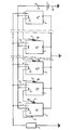
- a generator is thus obtained consisting of a cascade of thermal cells which are arranged in parallel on a device to be supplied and the activator of each of which is controlled by the thermal switch associated with the preceding thermal cell in the cascade, except for the first one which is ordered directly and voluntarily by an operator.
- the generator according to the invention comprises a plurality of thermal cells P 1 , P 2 , .. P i , .. P n of the type described above.
- Each of these batteries comprises a box 1, made of a conductive material and connected to the cathode, an anode 2 and an igniter (or activator) 3.
- the igniter 3 of the battery P 1 is supplied via the contact 6 and the housing 1 of the said battery. Consequently, the battery P 1 is activated and begins to deliver its energy to the user device 4.
- the rest of the operation of the device in the single figure may be different.
- the material 8 and the location on the housings 1 of the thermal switches 7,8 are each chosen so that the switch 7,8 of a P i-1 battery operates just before the moment when this P i-1 battery, activated, will finish delivering its energy to the device 4, so that the igniter 3 of the next battery P i is actuated at this time through the switch 7,8 and the housing 1 of the previous battery P i-1 .
- the thermal switches 7,8 and their arrangement are provided so that the n batteries Pi are activated simultaneously, that is to say so that all the switches 7,8 immediately reach their operating temperature and transmit the activation order from the battery P 2 to the battery P n .
- the user device 4 may require operating periods between which durations varying from seconds to ten years may elapse, each operating period being delimited by closing, then the opening of the switch 5. Within each of said operating periods, it is possible, in the manner described above, to activate one or more Pi batteries, successively or simultaneously.
- the energy required to control the igniters 3 is very low, so that the battery 4 which supplies it (or any other device, such as a piezoelectric system) can be very far from all of the batteries P i .
- one or more batteries P i can be provided with several thermal switches 7,8 to control other control and use chains.
Landscapes
- Chemical & Material Sciences (AREA)
- Chemical Kinetics & Catalysis (AREA)
- Electrochemistry (AREA)
- General Chemical & Material Sciences (AREA)
- Engineering & Computer Science (AREA)
- Manufacturing & Machinery (AREA)
- Primary Cells (AREA)
- Charge And Discharge Circuits For Batteries Or The Like (AREA)
- Control Of Electrical Variables (AREA)
- Secondary Cells (AREA)
- Electrochromic Elements, Electrophoresis, Or Variable Reflection Or Absorption Elements (AREA)
- Thermotherapy And Cooling Therapy Devices (AREA)
- Electromechanical Clocks (AREA)
Priority Applications (1)
| Application Number | Priority Date | Filing Date | Title |
|---|---|---|---|
| AT84402315T ATE52359T1 (de) | 1983-11-16 | 1984-11-14 | Mindestens eine thermische zelle enthaltende vorrichtung und ihre verwendung als modulierbarer energiegenerator. |
Applications Claiming Priority (2)
| Application Number | Priority Date | Filing Date | Title |
|---|---|---|---|
| FR8318206 | 1983-11-16 | ||
| FR8318206A FR2554973B1 (fr) | 1983-11-16 | 1983-11-16 | Dispositif electrique comportant au moins une pile thermique et son application a un generateur d'energie modulable |
Publications (3)
| Publication Number | Publication Date |
|---|---|
| EP0145559A2 true EP0145559A2 (de) | 1985-06-19 |
| EP0145559A3 EP0145559A3 (de) | 1985-07-10 |
| EP0145559B1 EP0145559B1 (de) | 1990-04-25 |
Family
ID=9294174
Family Applications (1)
| Application Number | Title | Priority Date | Filing Date |
|---|---|---|---|
| EP84402315A Expired - Lifetime EP0145559B1 (de) | 1983-11-16 | 1984-11-14 | Mindestens eine thermische Zelle enthaltende Vorrichtung und ihre Verwendung als modulierbarer Energiegenerator |
Country Status (7)
| Country | Link |
|---|---|
| US (1) | US4585713A (de) |
| EP (1) | EP0145559B1 (de) |
| JP (1) | JPH0756806B2 (de) |
| AT (1) | ATE52359T1 (de) |
| CA (1) | CA1221151A (de) |
| DE (1) | DE3482079D1 (de) |
| FR (1) | FR2554973B1 (de) |
Families Citing this family (9)
| Publication number | Priority date | Publication date | Assignee | Title |
|---|---|---|---|---|
| US5006429A (en) * | 1989-08-24 | 1991-04-09 | The United States Of America As Represented By The Secretary Of The Navy | Externally heated thermal battery |
| US5206456A (en) * | 1989-08-24 | 1993-04-27 | The United States Of America As Represented By The Secretary Of The Navy | Ordinance thermal battery |
| JPH0946893A (ja) * | 1995-07-28 | 1997-02-14 | Honda Motor Co Ltd | 組バッテリの監視装置および保護装置 |
| US6475662B1 (en) | 2000-06-05 | 2002-11-05 | Eagle-Picher Technologies, Llc | Thermal battery |
| CA2728383C (en) * | 2008-06-30 | 2015-04-14 | Abb Research Ltd | A battery unit arrangement for high voltage applications, connector and disconnector arrangement and method |
| CN102148378A (zh) * | 2011-02-28 | 2011-08-10 | 崔志国 | 一种电解质热电池及其工艺和原理 |
| US10670381B1 (en) * | 2013-09-17 | 2020-06-02 | The United States Of America, As Represented By The Secretary Of The Navy | Electronic thermally-initiated venting system (ETIVS) for rocket motors |
| KR102236307B1 (ko) * | 2020-12-10 | 2021-04-05 | 국방과학연구소 | 열전지 시스템 및 그의 착화 방법 |
| US20240339857A1 (en) * | 2023-04-05 | 2024-10-10 | Raytheon Company | Power management unit battery boost converter |
Family Cites Families (13)
| Publication number | Priority date | Publication date | Assignee | Title |
|---|---|---|---|---|
| FR1088450A (fr) * | 1953-10-19 | 1955-03-07 | Photographiques Modernes Lab | Système d'obturation pour éléments de piles électriques |
| US4156057A (en) * | 1961-06-01 | 1979-05-22 | National Union Electric Corporation | Secondary heat system for thermal batteries |
| FR1503730A (fr) * | 1966-10-11 | 1967-12-01 | Nord Aviation | Perfectionnement aux piles électriques à amorçage thermique |
| FR1597052A (de) * | 1968-12-23 | 1970-06-22 | ||
| US3625767A (en) * | 1969-12-17 | 1971-12-07 | Atomic Energy Commission | Thermal battery |
| US3639773A (en) * | 1970-03-20 | 1972-02-01 | Catalyst Research Corp | Thermal battery initiation sequencer |
| US3689776A (en) * | 1970-08-25 | 1972-09-05 | Us Army | Isolation of parallel cell stacks in thermal batteries by a squib switch |
| GB1342334A (en) * | 1972-05-30 | 1974-01-03 | Bogue J C | Battery power supply system |
| JPS4929367A (de) * | 1972-07-18 | 1974-03-15 | ||
| US3855003A (en) * | 1974-01-02 | 1974-12-17 | Atomic Energy Commission | Thermal sensing, fire safing device for a thermal battery |
| JPS5443245Y2 (de) * | 1974-08-15 | 1979-12-14 | ||
| DE2819583C2 (de) * | 1978-05-05 | 1983-01-20 | Brown, Boveri & Cie Ag, 6800 Mannheim | Elektrochemische Speicherzelle |
| US4274043A (en) * | 1978-12-21 | 1981-06-16 | The Dow Chemical Company | Efficient, high power battery module; D.C. transformers and multi-terminal D.C. power networks utilizing same |
-
1983
- 1983-11-16 FR FR8318206A patent/FR2554973B1/fr not_active Expired
-
1984
- 1984-11-14 AT AT84402315T patent/ATE52359T1/de not_active IP Right Cessation
- 1984-11-14 DE DE8484402315T patent/DE3482079D1/de not_active Expired - Fee Related
- 1984-11-14 US US06/671,440 patent/US4585713A/en not_active Expired - Fee Related
- 1984-11-14 JP JP59240375A patent/JPH0756806B2/ja not_active Expired - Lifetime
- 1984-11-14 EP EP84402315A patent/EP0145559B1/de not_active Expired - Lifetime
- 1984-11-16 CA CA000468085A patent/CA1221151A/fr not_active Expired
Also Published As
| Publication number | Publication date |
|---|---|
| EP0145559A3 (de) | 1985-07-10 |
| ATE52359T1 (de) | 1990-05-15 |
| DE3482079D1 (de) | 1990-05-31 |
| JPH0756806B2 (ja) | 1995-06-14 |
| CA1221151A (fr) | 1987-04-28 |
| EP0145559B1 (de) | 1990-04-25 |
| JPS60125131A (ja) | 1985-07-04 |
| US4585713A (en) | 1986-04-29 |
| FR2554973A1 (fr) | 1985-05-17 |
| FR2554973B1 (fr) | 1986-02-28 |
Similar Documents
| Publication | Publication Date | Title |
|---|---|---|
| EP0145559B1 (de) | Mindestens eine thermische Zelle enthaltende Vorrichtung und ihre Verwendung als modulierbarer Energiegenerator | |
| FR2737605A1 (fr) | Commutateur de mise en court-circuit active thermiquement destine a un element de batterie | |
| EP0017892A1 (de) | Automatische Umschaltvorrichtung zum parallelen Aufladen und serienmässigen Entladen zweier Batterien | |
| EP2415139A2 (de) | Verfahren zum sichern des betriebs einer elektrischen batterie | |
| FR2492157A1 (fr) | Dispositif combine de demarrage et de protection de moteur electrique monophase utilisant une thermistance de demarrage | |
| FR2916933A1 (fr) | Dispositif de connexion electrique entre une source d'alimentation electrique et un radiateur electrique, et procede de realisation d'un tel dispositif de connexion | |
| EP1111751B1 (de) | Schutzvorrichtung für Batteriezellen und Batterie mit einer solchen Vorrichtung | |
| FR2496352A1 (fr) | Procede et dispositif pour charger une batterie d'accumulateurs electriques au moyen de cellules solaires | |
| EP3624232A1 (de) | Vorrichtung zum lichtbogenblasen mithilfe von druckgas bei einer verbindung/trennung zwischen einer ausgangsklemme eines elektrochemischen akkus und einer sammelschiene | |
| EP0341159B1 (de) | Elektrischer Kapazitiver Energiespeicher mit grosser Kapazität | |
| WO2010063913A2 (fr) | Dispositif d'alimentation électrique, et installation de commande d'un sectionneur incluant un tel dispositif | |
| CA2975354A1 (fr) | Systeme de commande d'au moins un detonateur electronique | |
| FR3085796A1 (fr) | Dispositif de connexion/deconnexion magnetique entre un accumulateur electrochimique et des busbars, et de shunt magnetique passif de l'accumulateur apres sa chute par gravite | |
| EP1825557B1 (de) | Verfahren zur steuerung einer wiederaufladbaren batterie und wiederaufladbare batterie zur ausführung des verfahrens | |
| FR2743452A1 (fr) | Dispositif de securite pour generateur electrochimique | |
| EP0323328B1 (de) | Tragbare elektrische Vorrichtung zur Dampferzeugung, insbesondere zum Entfernen von Wandbekleidung | |
| EP3339981B1 (de) | Armbanduhr, die mit einem thermoelektrischen druckknopf ausgestattet ist | |
| FR3085797A1 (fr) | Borne de sortie d'un accumulateur electrochimique integrant un verrou magnetique pour fixation magnetique avec conduction electrique avec un busbar | |
| FR3085798A1 (fr) | Adaptateur d'interface integrant au moins un verrou magnetique pour fixation magnetique avec conduction electrique d'un accumulateur electrochimique a un busbar | |
| FR2824632A1 (fr) | Dispositif de commande sequentielle d'elements pyrotechniques integres dans un module electronique | |
| EP0191484B1 (de) | Primär- oder Sekundärelektrochemischer Generator | |
| EP1971992A1 (de) | Vorrichtung zur prüfung von mindestens zwei akkumulatoren und ladeverfahren unter verwendung einer derartigen prüfvorrichtung | |
| CH680691A5 (en) | Battery life extending technique - includes use of switching circuit introducing new cells in series after voltage falls below threshold | |
| FR2555366A1 (fr) | Dispositif d'alimentation electrique amorcable par un liquide | |
| FR3165119A1 (fr) | Station d’alimentation électrique mobile rechargeable |
Legal Events
| Date | Code | Title | Description |
|---|---|---|---|
| PUAI | Public reference made under article 153(3) epc to a published international application that has entered the european phase |
Free format text: ORIGINAL CODE: 0009012 |
|
| PUAL | Search report despatched |
Free format text: ORIGINAL CODE: 0009013 |
|
| AK | Designated contracting states |
Designated state(s): AT BE CH DE GB IT LI NL SE |
|
| AK | Designated contracting states |
Designated state(s): AT BE CH DE GB IT LI NL SE |
|
| RTI1 | Title (correction) | ||
| 17P | Request for examination filed |
Effective date: 19850605 |
|
| RAP1 | Party data changed (applicant data changed or rights of an application transferred) |
Owner name: AEROSPATIALE SOCIETE NATIONALE INDUSTRIELLE |
|
| 17Q | First examination report despatched |
Effective date: 19870127 |
|
| GRAA | (expected) grant |
Free format text: ORIGINAL CODE: 0009210 |
|
| RAP1 | Party data changed (applicant data changed or rights of an application transferred) |
Owner name: AEROSPATIALE SOCIETE NATIONALE INDUSTRIELLE |
|
| AK | Designated contracting states |
Kind code of ref document: B1 Designated state(s): AT BE CH DE GB IT LI NL SE |
|
| REF | Corresponds to: |
Ref document number: 52359 Country of ref document: AT Date of ref document: 19900515 Kind code of ref document: T |
|
| GBT | Gb: translation of ep patent filed (gb section 77(6)(a)/1977) | ||
| REF | Corresponds to: |
Ref document number: 3482079 Country of ref document: DE Date of ref document: 19900531 |
|
| ITF | It: translation for a ep patent filed | ||
| PLBE | No opposition filed within time limit |
Free format text: ORIGINAL CODE: 0009261 |
|
| STAA | Information on the status of an ep patent application or granted ep patent |
Free format text: STATUS: NO OPPOSITION FILED WITHIN TIME LIMIT |
|
| 26N | No opposition filed | ||
| ITTA | It: last paid annual fee | ||
| PGFP | Annual fee paid to national office [announced via postgrant information from national office to epo] |
Ref country code: CH Payment date: 19941024 Year of fee payment: 11 |
|
| PGFP | Annual fee paid to national office [announced via postgrant information from national office to epo] |
Ref country code: SE Payment date: 19941028 Year of fee payment: 11 Ref country code: AT Payment date: 19941028 Year of fee payment: 11 |
|
| PGFP | Annual fee paid to national office [announced via postgrant information from national office to epo] |
Ref country code: GB Payment date: 19941104 Year of fee payment: 11 |
|
| PGFP | Annual fee paid to national office [announced via postgrant information from national office to epo] |
Ref country code: DE Payment date: 19941107 Year of fee payment: 11 |
|
| PGFP | Annual fee paid to national office [announced via postgrant information from national office to epo] |
Ref country code: NL Payment date: 19941130 Year of fee payment: 11 |
|
| PGFP | Annual fee paid to national office [announced via postgrant information from national office to epo] |
Ref country code: BE Payment date: 19950111 Year of fee payment: 11 |
|
| EAL | Se: european patent in force in sweden |
Ref document number: 84402315.0 |
|
| PG25 | Lapsed in a contracting state [announced via postgrant information from national office to epo] |
Ref country code: GB Effective date: 19951114 Ref country code: AT Effective date: 19951114 |
|
| PG25 | Lapsed in a contracting state [announced via postgrant information from national office to epo] |
Ref country code: SE Effective date: 19951115 |
|
| PG25 | Lapsed in a contracting state [announced via postgrant information from national office to epo] |
Ref country code: LI Effective date: 19951130 Ref country code: CH Effective date: 19951130 Ref country code: BE Effective date: 19951130 |
|
| BERE | Be: lapsed |
Owner name: AEROSPATIALE SOC. NATIONALE INDUSTRIELLE Effective date: 19951130 |
|
| PG25 | Lapsed in a contracting state [announced via postgrant information from national office to epo] |
Ref country code: NL Effective date: 19960601 |
|
| GBPC | Gb: european patent ceased through non-payment of renewal fee |
Effective date: 19951114 |
|
| REG | Reference to a national code |
Ref country code: CH Ref legal event code: PL |
|
| NLV4 | Nl: lapsed or anulled due to non-payment of the annual fee |
Effective date: 19960601 |
|
| PG25 | Lapsed in a contracting state [announced via postgrant information from national office to epo] |
Ref country code: DE Effective date: 19960801 |
|
| EUG | Se: european patent has lapsed |
Ref document number: 84402315.0 |