EP0341159B1 - Elektrischer Kapazitiver Energiespeicher mit grosser Kapazität - Google Patents
Elektrischer Kapazitiver Energiespeicher mit grosser Kapazität Download PDFInfo
- Publication number
- EP0341159B1 EP0341159B1 EP89401265A EP89401265A EP0341159B1 EP 0341159 B1 EP0341159 B1 EP 0341159B1 EP 89401265 A EP89401265 A EP 89401265A EP 89401265 A EP89401265 A EP 89401265A EP 0341159 B1 EP0341159 B1 EP 0341159B1
- Authority
- EP
- European Patent Office
- Prior art keywords
- capacitors
- energy accumulator
- case
- electric energy
- shunts
- Prior art date
- Legal status (The legal status is an assumption and is not a legal conclusion. Google has not performed a legal analysis and makes no representation as to the accuracy of the status listed.)
- Expired - Lifetime
Links
Images

Classifications
-
- H—ELECTRICITY
- H01—ELECTRIC ELEMENTS
- H01G—CAPACITORS; CAPACITORS, RECTIFIERS, DETECTORS, SWITCHING DEVICES, LIGHT-SENSITIVE OR TEMPERATURE-SENSITIVE DEVICES OF THE ELECTROLYTIC TYPE
- H01G9/00—Electrolytic capacitors, rectifiers, detectors, switching devices, light-sensitive or temperature-sensitive devices; Processes of their manufacture
- H01G9/004—Details
- H01G9/08—Housing; Encapsulation
-
- H—ELECTRICITY
- H02—GENERATION; CONVERSION OR DISTRIBUTION OF ELECTRIC POWER
- H02H—EMERGENCY PROTECTIVE CIRCUIT ARRANGEMENTS
- H02H7/00—Emergency protective circuit arrangements specially adapted for specific types of electric machines or apparatus or for sectionalised protection of cable or line systems, and effecting automatic switching in the event of an undesired change from normal working conditions
- H02H7/16—Emergency protective circuit arrangements specially adapted for specific types of electric machines or apparatus or for sectionalised protection of cable or line systems, and effecting automatic switching in the event of an undesired change from normal working conditions for capacitors
-
- Y—GENERAL TAGGING OF NEW TECHNOLOGICAL DEVELOPMENTS; GENERAL TAGGING OF CROSS-SECTIONAL TECHNOLOGIES SPANNING OVER SEVERAL SECTIONS OF THE IPC; TECHNICAL SUBJECTS COVERED BY FORMER USPC CROSS-REFERENCE ART COLLECTIONS [XRACs] AND DIGESTS
- Y02—TECHNOLOGIES OR APPLICATIONS FOR MITIGATION OR ADAPTATION AGAINST CLIMATE CHANGE
- Y02E—REDUCTION OF GREENHOUSE GAS [GHG] EMISSIONS, RELATED TO ENERGY GENERATION, TRANSMISSION OR DISTRIBUTION
- Y02E60/00—Enabling technologies; Technologies with a potential or indirect contribution to GHG emissions mitigation
- Y02E60/13—Energy storage using capacitors
Definitions
- the present invention relates to a capacitive type electrical energy accumulator, of large capacity, comprising a plurality of electrochemical capacitors connected in parallel, an overvoltage detection circuit and a discharge circuit for discharging the capacitors in heat dissipation shunts from that an abnormal overvoltage is detected.
- Such an electrical energy accumulator is applicable in particular to an electrical control system, with energy recovery, of the turret of a battle tank.
- the patent FR-A-606 801 describes an electric energy accumulator of the capacitive type comprising, for each capacitor, a circuit for detecting overvoltage and discharge in a heat dissipation shunt. In addition, nothing is planned to avoid the risk of electric shock.
- the main object of the present invention is therefore to produce a large capacity accumulator which at the same time has great job security.
- the accumulator according to the invention is essentially characterized in that the plurality of electrochemical capacitors is arranged inside the same housing comprising the detection circuit and a discharge control circuit in which the housing is integrated. dissipation shunts thermal, and in that this box consists of a receptacle provided with a cover and comprises a device for detecting the opening of the cover automatically triggering the discharge of the capacitors.
- the capacitors are distributed inside each box in several batteries each associated with a fuse.
- a damage detector is provided in order to locate the faulty capacitor bank.
- the fuse is destroyed and isolates the corresponding battery, which does not jeopardize the proper functioning of the assembly.
- the faulty battery is located and can then be repaired as soon as the conditions of use allow it.
- the housing is produced in the form of a circular sector capable of being joined to other identical housings to form an at least partial crown.
- the capacitive accumulator shown in FIG. 1 has a relatively large capacity of the order of 0.25 Farad and it is essentially constituted by the parallel connection of 20 electrochemical capacitors C of 12,500 ⁇ F each.
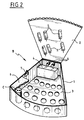
- all of these capacitors are arranged inside the same housing B, shown in FIG. 2, which is equipped with an overvoltage detection circuit DS controlling a discharge switch CD connected in series with heat dissipation shunts S integrated into the housing.
- the capacitors are normally subjected to a nominal voltage of the order of 270 volts and when an abnormal overvoltage is detected by the DS circuit, the switch CD closes and causes the immediate discharge of the capacitors in the shunts S in a time less than 2 seconds.
- the DS overvoltage detector is also provided with a control external to the CE casing allowing the capacitors to discharge voluntarily outside the periods of use of the system.
- the capacitors C are distributed inside the housing B into four identical batteries A1 ... A4 of five capacitors, each associated with a fuse F.
- a short type damage -circuit appears on one of the capacitors, it destroys the fuse of the corresponding battery.
- the faulty battery is then isolated, which does not prevent the other batteries from operating normally.
- a damage detector DA is also provided, with a connection to the outside CA making it possible to locate the box in which the faulty battery, in order to repair it as soon as the conditions of use allow it.
- the housing B is essentially constituted by a receptacle 1 in the form of a circular sector, of approximately 60 ° angle at the top, closed in leaktight manner by a cover 2.
- the capacitors C are arranged upright and staggered on a honeycombed bottom plate 3, made for example of Teflon, in four successive rows corresponding respectively to the four batteries A1 to A4.
- an electronic unit 4 containing the overvoltage detector DS, the discharge switch CD and the damage detector DA.
- connectors 5 for ensuring connections with the outside of the electronic unit 4 and the capacitors C.
- the assembly is covered with a block of foam 6 ensuring the maintenance of the capacitors in the cells of the bottom plate 3.
- the shunts S are fixed on the internal face of the cover 2 including the external face of the grooves in order to constitute a thermal radiator. Furthermore, a contactor 7 is placed inside the receptacle 1 so as to be biased by the cover 2 in the closed position. Thus, when the cover is opened for any reason, the contactor 7 is actuated and then automatically causes the capacitors to discharge in the shunts S, in order to avoid any risk of electrocution.
- the capacitive accumulator according to the invention has both high job security and high operational availability due to its cellular organization.
- the particular application envisaged here namely the electric motorization of the turret of a combat tank
- an accumulator having a large capacity of the order of 1 Farad there is in fact a need for an accumulator having a large capacity of the order of 1 Farad. It is then necessary to associate several boxes such as that which has just been described, and the particular shape of these boxes makes it possible to produce, by juxtaposition, partial crowns which integrate perfectly into the turret of a tank.
Landscapes
- Engineering & Computer Science (AREA)
- Power Engineering (AREA)
- Microelectronics & Electronic Packaging (AREA)
- Electric Double-Layer Capacitors Or The Like (AREA)
- Charge And Discharge Circuits For Batteries Or The Like (AREA)
- Connection Of Batteries Or Terminals (AREA)
- Secondary Cells (AREA)
Claims (4)
- Elektrischer kapazitiver Energiespeicher mit großer Kapazität, enthaltend eine Vielzahl parallelgeschalteter elektrochemischer Kondensatoren (C), einen Überspannungs-Überwachungskreis (DS) und einen Entladungskreis (CD, S), um die Kondensatoren in Wärmeabstrahlungs-Shunts (S) zu entladen, sowie eine anormale Überspannung festgestellt wird,
dadurch gekennzeichnet,
daß die Vielzahl elektrochemischer Kondenstoren (C) im Inneren desselben Gehäuses (B) untergebracht ist, das den Überwachungskreis (DS) und einen Entladungssteuerkreis (CD) enthält und in das die Wärmeabstrahlungs-Shunts (S) integriert sind, und dadurch, daß dieses Gehäuse gebildet wird durch einen Behälter (1), versehen mit einem Deckel (2), und eine Überwachungseinrichtung (7) für die Öffung des Deckels (2) umfaßt, die automatisch die Entladung der Kondensatoren (C) auslöst. - Elektrischer Energiespeicher nach Anspruch 1, dadurch gekennzeichnet, daß die Kondensatoren (C) im Inneren eines jeden Gehäuses auf mehrere Batterien verteilt sind (A₁...A₄), wobei jede einer Sicherung (F) zugeordnet ist.
- Elektrischer Energiespeicher nach Anspruch 2, dadurch gekennzeichnet, daß er eine Störfalldetektor (DA) enthält, der gestattet, die ausgefallene Batterie zu lokalisieren.
- Elektrischer Energiespeicher nach einem der Ansprüche 1 bis 3, dadurch gekennzeichnet, daß das Gehäuse (B) ausgeführt ist in der Form eines Kreissektors, geeignet, an weitere identische Gehäuse angefügt zu werden, um einen, wenigstens partiellen Kranz zu bilden.
Priority Applications (1)
| Application Number | Priority Date | Filing Date | Title |
|---|---|---|---|
| AT89401265T ATE92680T1 (de) | 1988-05-06 | 1989-05-03 | Elektrischer kapazitiver energiespeicher mit grosser kapazitaet. |
Applications Claiming Priority (2)
| Application Number | Priority Date | Filing Date | Title |
|---|---|---|---|
| FR8806162A FR2631156B1 (fr) | 1988-05-06 | 1988-05-06 | Accumulateur d'energie electrique de type capacitif, de grande capacite |
| FR8806162 | 1988-05-06 |
Publications (2)
| Publication Number | Publication Date |
|---|---|
| EP0341159A1 EP0341159A1 (de) | 1989-11-08 |
| EP0341159B1 true EP0341159B1 (de) | 1993-08-04 |
Family
ID=9366097
Family Applications (1)
| Application Number | Title | Priority Date | Filing Date |
|---|---|---|---|
| EP89401265A Expired - Lifetime EP0341159B1 (de) | 1988-05-06 | 1989-05-03 | Elektrischer Kapazitiver Energiespeicher mit grosser Kapazität |
Country Status (9)
| Country | Link |
|---|---|
| US (1) | US5073751A (de) |
| EP (1) | EP0341159B1 (de) |
| AT (1) | ATE92680T1 (de) |
| CA (1) | CA1310690C (de) |
| DE (2) | DE68907995T2 (de) |
| ES (1) | ES2015846T3 (de) |
| FR (1) | FR2631156B1 (de) |
| GR (1) | GR900300145T1 (de) |
| IL (1) | IL90195A (de) |
Families Citing this family (11)
| Publication number | Priority date | Publication date | Assignee | Title |
|---|---|---|---|---|
| US5574967A (en) * | 1994-01-11 | 1996-11-12 | Ericsson Ge Mobile Communications, Inc. | Waste energy control and management in power amplifiers |
| US6005370A (en) * | 1998-01-26 | 1999-12-21 | Physio-Control Manufacturing Corporation | Automatic rate control for defibrillator capacitor charging |
| FR2774222B1 (fr) * | 1998-01-27 | 2000-04-14 | Sextant Avionique | Dispositif de reserve d'energie en courant electrique continu |
| EP1033730B1 (de) * | 1999-02-04 | 2008-06-11 | Advanced Capacitor Technologies, Inc. | Kondensatormodul, Gruppe von Modulen und Gehäuse für solche Modulen |
| DE10304557A1 (de) * | 2003-02-05 | 2004-08-19 | Bayerische Motoren Werke Ag | Kondensatorbatterie und Verfahren zu deren Ansteuerung |
| JP4237733B2 (ja) * | 2004-08-02 | 2009-03-11 | 株式会社リコー | 補助電源ユニットおよび画像形成装置 |
| DE102005018339A1 (de) * | 2005-04-20 | 2006-10-26 | Siemens Ag | Anordnung mit einem Kondensatormodul und Verfahren zu dessen Betrieb |
| JP4509852B2 (ja) * | 2005-05-17 | 2010-07-21 | 株式会社東芝 | 組電池装置とその電圧検出装置 |
| DE102005055075A1 (de) | 2005-11-18 | 2007-05-24 | Bayerische Motoren Werke Ag | Kraftfahrzeug mit einer Kondensatoreinrichtung zur Speicherung elektrischer Energie |
| DE102008061585B4 (de) * | 2008-12-11 | 2019-02-21 | Conti Temic Microelectronic Gmbh | Fahrzeug mit Versorgungseinrichtung eines Elektromotors und Verfahren zur Stromversorgung des Elektromotors |
| DE102012020019B4 (de) * | 2012-10-12 | 2015-04-02 | Audi Ag | Entladevorrichtung zum aktiven Entladen eines Hochvolt-Zwischenkreises in einem Hochvolt-Netz eines Fahrzeugs und Fahrzeug mit einer solchen Entladevorrichtung |
Family Cites Families (9)
| Publication number | Priority date | Publication date | Assignee | Title |
|---|---|---|---|---|
| FR606801A (fr) * | 1924-11-24 | 1926-06-21 | Dubilier Condenser Co 1925 Ltd | Condensateur électrique protégé par un dispositif à décharge par distances explosives |
| US2660694A (en) * | 1951-02-23 | 1953-11-24 | Westinghouse Electric Corp | Housed capacitor assembly with interlocked grounding switch |
| US3692401A (en) * | 1969-08-01 | 1972-09-19 | Minolta Camera Kk | Safety system in electrostatic copier |
| US3628091A (en) * | 1970-05-13 | 1971-12-14 | Bouligny Inc R H | Resonance suppressor for electrical system including capacitors |
| JPS5942536B2 (ja) * | 1974-07-10 | 1984-10-16 | 三菱電機株式会社 | 直列コンデンサの保護装置 |
| US4295174A (en) * | 1979-05-29 | 1981-10-13 | Westinghouse Electric Corp. | Multi-series group capacitor bank protection equipment |
| US4347539A (en) * | 1981-06-03 | 1982-08-31 | Westinghouse Electric Corp. | Electrical equipment protective apparatus with energy balancing among parallel varistors |
| FR2559321B1 (fr) * | 1984-02-06 | 1986-11-21 | Applic Mach Motrices | Dispositif d'entrainement electrique en basse tension d'une masse tournante de forte inertie et moteur faisant partie de ce dispositif |
| FR2598024B1 (fr) * | 1986-04-29 | 1990-04-27 | Merlin Gerin | Condensateur basse tension autoprotege |
-
1988
- 1988-05-06 FR FR8806162A patent/FR2631156B1/fr not_active Expired - Fee Related
-
1989
- 1989-05-03 ES ES89401265T patent/ES2015846T3/es not_active Expired - Lifetime
- 1989-05-03 DE DE89401265T patent/DE68907995T2/de not_active Expired - Fee Related
- 1989-05-03 EP EP89401265A patent/EP0341159B1/de not_active Expired - Lifetime
- 1989-05-03 DE DE198989401265T patent/DE341159T1/de active Pending
- 1989-05-03 AT AT89401265T patent/ATE92680T1/de not_active IP Right Cessation
- 1989-05-04 IL IL9019589A patent/IL90195A/en unknown
- 1989-05-05 CA CA000598818A patent/CA1310690C/fr not_active Expired - Lifetime
- 1989-05-05 US US07/348,263 patent/US5073751A/en not_active Expired - Lifetime
-
1991
- 1991-09-27 GR GR90300145T patent/GR900300145T1/el unknown
Also Published As
| Publication number | Publication date |
|---|---|
| ES2015846T3 (es) | 1994-01-01 |
| FR2631156A1 (fr) | 1989-11-10 |
| DE341159T1 (de) | 1990-10-18 |
| ES2015846A4 (es) | 1990-09-16 |
| DE68907995T2 (de) | 1994-02-24 |
| CA1310690C (fr) | 1992-11-24 |
| DE68907995D1 (de) | 1993-09-09 |
| GR900300145T1 (en) | 1991-09-27 |
| FR2631156B1 (fr) | 1994-07-22 |
| EP0341159A1 (de) | 1989-11-08 |
| US5073751A (en) | 1991-12-17 |
| ATE92680T1 (de) | 1993-08-15 |
| IL90195A (en) | 1994-06-24 |
Similar Documents
| Publication | Publication Date | Title |
|---|---|---|
| EP0341159B1 (de) | Elektrischer Kapazitiver Energiespeicher mit grosser Kapazität | |
| EP1130202B1 (de) | Verriegelungseinrichtung für eine Kraftfahrzeugtür und Verfahren zur Funktionsprüfung eines Schlossmoduls dieser Einrichtung | |
| FR2494503A1 (fr) | Dispositif de batteries | |
| FR2635406A1 (fr) | Disjoncteur equipe d'une unite amovible constituee d'un ensemble de visualisation et d'un clavier | |
| FR2883665A1 (fr) | Dispositif d'alimentation electrique pour vehicule automobile | |
| EP1764891A1 (de) | Elektronische Auslösevorrichtung mit Überwachungsmittel und entsprechendes Überwachungsverfahren | |
| FR2858722A1 (fr) | Dispositif d'alimentation electrique pour vehicule a moteur | |
| EP3066707B1 (de) | Speicherbatterie mit ununterbrochener dienstleistung im störungsfall | |
| EP1111751B1 (de) | Schutzvorrichtung für Batteriezellen und Batterie mit einer solchen Vorrichtung | |
| FR2964506A1 (fr) | Dispositif et procede de limitation de courants de fuite | |
| FR2916579A1 (fr) | Boitier electronique pour batterie. | |
| EP2363939B1 (de) | Unterbrechungsfreie Wechselstromversorgung einer Installation und Verfahren dazu | |
| FR2770050A1 (fr) | Dispositif de securite d'un accumulateur electrochimique | |
| WO2018167306A1 (fr) | Systeme d'alimentation en energie electrique d'un reseau de bord d'un sous-marin | |
| FR2743452A1 (fr) | Dispositif de securite pour generateur electrochimique | |
| EP2997588A1 (de) | Isolator für gleichstrom-stromversorgungsquelle | |
| EP0918388B1 (de) | Elektrischer Fehlerschutz in einem Datenspeichersystem | |
| EP0145559A2 (de) | Mindestens eine thermische Zelle enthaltende Vorrichtung und ihre Verwendung als modulierbarer Energiegenerator | |
| FR2845837A1 (fr) | Dispositif d'alimentation en energie electrique, notamment d'un actionneur electromecanique | |
| EP0909000B1 (de) | Schutzeinrichtung für eine Kondensatorbatterie | |
| EP3758180B1 (de) | Vorrichtung und verfahren zum schutz und/oder zur überwachung für elektrischen transformator vom typ mit dielektrischer flüssigkeit, die in einem hermetisch abgeschlossenen tank eingeschlossen ist | |
| FR2810809A1 (fr) | Dispositif d'alimentation pour appareils electriques portables | |
| EP4721228A1 (de) | Elektrische energiespeichereinheit | |
| FR2770407A1 (fr) | Appareil pour la destruction individuelle des aiguilles de seringue par fusion sous l'effet d'un courant electrique | |
| FR2778281A1 (fr) | Protection pour module de batterie |
Legal Events
| Date | Code | Title | Description |
|---|---|---|---|
| PUAI | Public reference made under article 153(3) epc to a published international application that has entered the european phase |
Free format text: ORIGINAL CODE: 0009012 |
|
| AK | Designated contracting states |
Kind code of ref document: A1 Designated state(s): AT BE CH DE ES GB GR IT LI LU NL SE |
|
| 17P | Request for examination filed |
Effective date: 19900327 |
|
| ITCL | It: translation for ep claims filed |
Representative=s name: ING. A. GIAMBROCONO & C. S.R.L. |
|
| GBC | Gb: translation of claims filed (gb section 78(7)/1977) | ||
| TCAT | At: translation of patent claims filed | ||
| TCNL | Nl: translation of patent claims filed | ||
| DET | De: translation of patent claims | ||
| 17Q | First examination report despatched |
Effective date: 19911127 |
|
| RAP1 | Party data changed (applicant data changed or rights of an application transferred) |
Owner name: GIAT INDUSTRIES Owner name: COMPAGNIE DE SIGNAUX ET D'EQUIPEMENTS ELECTRONIQUE |
|
| GRAA | (expected) grant |
Free format text: ORIGINAL CODE: 0009210 |
|
| AK | Designated contracting states |
Kind code of ref document: B1 Designated state(s): AT BE CH DE ES GB GR IT LI LU NL SE |
|
| REF | Corresponds to: |
Ref document number: 92680 Country of ref document: AT Date of ref document: 19930815 Kind code of ref document: T |
|
| REF | Corresponds to: |
Ref document number: 68907995 Country of ref document: DE Date of ref document: 19930909 |
|
| ITF | It: translation for a ep patent filed | ||
| GBT | Gb: translation of ep patent filed (gb section 77(6)(a)/1977) |
Effective date: 19931115 |
|
| REG | Reference to a national code |
Ref country code: GR Ref legal event code: FG4A Free format text: 3009632 |
|
| RAP2 | Party data changed (patent owner data changed or rights of a patent transferred) |
Owner name: GIAT INDUSTRIES Owner name: CSEE-DEFENSE |
|
| REG | Reference to a national code |
Ref country code: CH Ref legal event code: PUE Owner name: CSEE-DEFENSE |
|
| NLS | Nl: assignments of ep-patents |
Owner name: CSEE-DEFENSE TE PARIJS EN GIAT INDUSTRIES TE VERSA |
|
| REG | Reference to a national code |
Ref country code: GB Ref legal event code: 732E |
|
| PG25 | Lapsed in a contracting state [announced via postgrant information from national office to epo] |
Ref country code: LU Free format text: LAPSE BECAUSE OF NON-PAYMENT OF DUE FEES Effective date: 19940531 |
|
| PLBE | No opposition filed within time limit |
Free format text: ORIGINAL CODE: 0009261 |
|
| STAA | Information on the status of an ep patent application or granted ep patent |
Free format text: STATUS: NO OPPOSITION FILED WITHIN TIME LIMIT |
|
| 26N | No opposition filed | ||
| ITPR | It: changes in ownership of a european patent |
Owner name: CESSIONE;CSEE - DEFENSE |
|
| REG | Reference to a national code |
Ref country code: ES Ref legal event code: PC2A Owner name: CSEE-DEFENSE (TITULAR DEL 50%) |
|
| EAL | Se: european patent in force in sweden |
Ref document number: 89401265.7 |
|
| REG | Reference to a national code |
Ref country code: CH Ref legal event code: PUEA Free format text: GIAT INDUSTRIES;CSEE-DEFENSE TRANSFER- GIAT INDUSTRIES;CS DEFENSE |
|
| REG | Reference to a national code |
Ref country code: ES Ref legal event code: PC2A |
|
| NLS | Nl: assignments of ep-patents |
Owner name: CS DEFENSE;GIAT INDUSTRIES |
|
| REG | Reference to a national code |
Ref country code: GB Ref legal event code: 732E |
|
| REG | Reference to a national code |
Ref country code: GB Ref legal event code: IF02 |
|
| PGFP | Annual fee paid to national office [announced via postgrant information from national office to epo] |
Ref country code: AT Payment date: 20030415 Year of fee payment: 15 |
|
| PGFP | Annual fee paid to national office [announced via postgrant information from national office to epo] |
Ref country code: NL Payment date: 20030416 Year of fee payment: 15 |
|
| PGFP | Annual fee paid to national office [announced via postgrant information from national office to epo] |
Ref country code: SE Payment date: 20030417 Year of fee payment: 15 |
|
| PGFP | Annual fee paid to national office [announced via postgrant information from national office to epo] |
Ref country code: GR Payment date: 20030422 Year of fee payment: 15 |
|
| PGFP | Annual fee paid to national office [announced via postgrant information from national office to epo] |
Ref country code: GB Payment date: 20030425 Year of fee payment: 15 |
|
| PGFP | Annual fee paid to national office [announced via postgrant information from national office to epo] |
Ref country code: DE Payment date: 20030512 Year of fee payment: 15 |
|
| PGFP | Annual fee paid to national office [announced via postgrant information from national office to epo] |
Ref country code: ES Payment date: 20030514 Year of fee payment: 15 |
|
| PGFP | Annual fee paid to national office [announced via postgrant information from national office to epo] |
Ref country code: CH Payment date: 20030515 Year of fee payment: 15 |
|
| PGFP | Annual fee paid to national office [announced via postgrant information from national office to epo] |
Ref country code: BE Payment date: 20030603 Year of fee payment: 15 |
|
| PG25 | Lapsed in a contracting state [announced via postgrant information from national office to epo] |
Ref country code: GB Free format text: LAPSE BECAUSE OF NON-PAYMENT OF DUE FEES Effective date: 20040503 Ref country code: AT Free format text: LAPSE BECAUSE OF NON-PAYMENT OF DUE FEES Effective date: 20040503 |
|
| PG25 | Lapsed in a contracting state [announced via postgrant information from national office to epo] |
Ref country code: SE Free format text: LAPSE BECAUSE OF NON-PAYMENT OF DUE FEES Effective date: 20040504 Ref country code: ES Free format text: LAPSE BECAUSE OF NON-PAYMENT OF DUE FEES Effective date: 20040504 |
|
| PG25 | Lapsed in a contracting state [announced via postgrant information from national office to epo] |
Ref country code: LI Free format text: LAPSE BECAUSE OF NON-PAYMENT OF DUE FEES Effective date: 20040531 Ref country code: CH Free format text: LAPSE BECAUSE OF NON-PAYMENT OF DUE FEES Effective date: 20040531 Ref country code: BE Free format text: LAPSE BECAUSE OF NON-PAYMENT OF DUE FEES Effective date: 20040531 |
|
| BERE | Be: lapsed |
Owner name: *GIAT INDUSTRIES Effective date: 20040531 Owner name: S.A. *CS DEFENSE Effective date: 20040531 |
|
| PG25 | Lapsed in a contracting state [announced via postgrant information from national office to epo] |
Ref country code: NL Free format text: LAPSE BECAUSE OF NON-PAYMENT OF DUE FEES Effective date: 20041201 Ref country code: DE Free format text: LAPSE BECAUSE OF NON-PAYMENT OF DUE FEES Effective date: 20041201 |
|
| PG25 | Lapsed in a contracting state [announced via postgrant information from national office to epo] |
Ref country code: GR Free format text: LAPSE BECAUSE OF NON-PAYMENT OF DUE FEES Effective date: 20041203 |
|
| GBPC | Gb: european patent ceased through non-payment of renewal fee |
Effective date: 20040503 |
|
| EUG | Se: european patent has lapsed | ||
| REG | Reference to a national code |
Ref country code: CH Ref legal event code: PL |
|
| NLV4 | Nl: lapsed or anulled due to non-payment of the annual fee |
Effective date: 20041201 |
|
| PG25 | Lapsed in a contracting state [announced via postgrant information from national office to epo] |
Ref country code: IT Free format text: LAPSE BECAUSE OF NON-PAYMENT OF DUE FEES;WARNING: LAPSES OF ITALIAN PATENTS WITH EFFECTIVE DATE BEFORE 2007 MAY HAVE OCCURRED AT ANY TIME BEFORE 2007. THE CORRECT EFFECTIVE DATE MAY BE DIFFERENT FROM THE ONE RECORDED. Effective date: 20050503 |
|
| REG | Reference to a national code |
Ref country code: ES Ref legal event code: FD2A Effective date: 20040504 |