EP0145816B1 - Metronomischer Signalgeber und Verfahren zur Tempoangabe - Google Patents
Metronomischer Signalgeber und Verfahren zur Tempoangabe Download PDFInfo
- Publication number
- EP0145816B1 EP0145816B1 EP83307669A EP83307669A EP0145816B1 EP 0145816 B1 EP0145816 B1 EP 0145816B1 EP 83307669 A EP83307669 A EP 83307669A EP 83307669 A EP83307669 A EP 83307669A EP 0145816 B1 EP0145816 B1 EP 0145816B1
- Authority
- EP
- European Patent Office
- Prior art keywords
- tempo
- transmitter
- pulsing
- metronomic
- dynamo
- Prior art date
- Legal status (The legal status is an assumption and is not a legal conclusion. Google has not performed a legal analysis and makes no representation as to the accuracy of the status listed.)
- Expired
Links
- 230000011664 signaling Effects 0.000 title claims abstract description 16
- 238000000034 method Methods 0.000 title claims description 5
- 230000033001 locomotion Effects 0.000 claims abstract description 9
- 239000004020 conductor Substances 0.000 claims description 7
- 230000000694 effects Effects 0.000 claims description 4
- 230000005540 biological transmission Effects 0.000 claims description 3
- 238000010079 rubber tapping Methods 0.000 claims description 3
- 230000003534 oscillatory effect Effects 0.000 claims 1
- 239000000463 material Substances 0.000 abstract description 5
- XEEYBQQBJWHFJM-UHFFFAOYSA-N Iron Chemical compound [Fe] XEEYBQQBJWHFJM-UHFFFAOYSA-N 0.000 abstract description 4
- 230000000295 complement effect Effects 0.000 abstract description 4
- 229910052742 iron Inorganic materials 0.000 abstract description 2
- 230000001276 controlling effect Effects 0.000 description 2
- 238000010586 diagram Methods 0.000 description 2
- 230000000737 periodic effect Effects 0.000 description 2
- 230000000007 visual effect Effects 0.000 description 2
- 239000011324 bead Substances 0.000 description 1
- 239000003990 capacitor Substances 0.000 description 1
- 230000001351 cycling effect Effects 0.000 description 1
- 230000009977 dual effect Effects 0.000 description 1
- 239000013013 elastic material Substances 0.000 description 1
- 230000003287 optical effect Effects 0.000 description 1
- 230000002093 peripheral effect Effects 0.000 description 1
- 239000004033 plastic Substances 0.000 description 1
- 230000001105 regulatory effect Effects 0.000 description 1
- 230000001360 synchronised effect Effects 0.000 description 1
Images

Classifications
-
- G—PHYSICS
- G04—HOROLOGY
- G04F—TIME-INTERVAL MEASURING
- G04F5/00—Apparatus for producing preselected time intervals for use as timing standards
- G04F5/02—Metronomes
Definitions
- This invention relates to silent metronomic signal pulsing devices.
- Metronomic devices make it possible to train or guide players of musical or similar activities a more accurate timing by a regularly repeated beat signals emitted from the devices at a rate ranging from 40 to 208 per minute.
- Audible (acoustic) and visual (optical) are two types of metronome widely known, while the former produces ticking sound and the latter produces oscillating light or pendulum.
- Another is a combination of the audible type with a skin felt addition and is known from US-A-2,535,809, cf the first six lines of claim 8 specifying "a case including a back wall comprising a flexible diaphragm, a timing mechanism within the case, means responsible to operation of the timing mechanism for creating uniformly periodic impacts in the diaphragm", and column 1, lines 25 to 28 specifying: "my timing device may be considered as being in the nature of a silent metronome in that it supplies sensible but substantially inaudible periodic beats".
- the device powered by a main spring is regulated by a clockwork mechanism including an escape wheel, 8 striking members and pallet fingers.
- the impact actions by the striker members of the escape wheel against the pallet fingers cause the casing to resonate and the shaft transmits the impact to the diaphragm thereby causing it to amplify the striking sound further to a distinct tick similarly as a regular audible metronome.
- the ticking sound or noise will render the device useless in an actual performance such as studio recording session where the microphones are sensitive enough to pick up even a slightest sound or noise emitted by the device.
- the lack of synchronising or inter-connecting means of the device in the reference further hinders the application of a method whereby the tempo signals may be effected to a plurality of users tacitly from a central location remote from the users.
- a silent metronomic signal pulsing device comprising: a housing having an opening; a transmitter fixed across said opening and having a face projecting from said housing for tempo-signal-imparting engagement with a user; transducer means comprising a disk-like member movable with said transmitter; dynamoelectric means having a part fixed to said member and a part fixed to said housing and operable for pulsing said member and thereby actuating said transmitter for tempo signal guidance of the user without acoustical interferences; and electrical means for controlling the pulsing tempo of the dynamo-electric means, characterised in that said face is texture accentuated by an array of projections which in operation thrust toward and tacitly impart a silent motion impulse to the skin of the user contacted by the pad face of the transmitter so that the transmitter is soundproof and clap-proof, and in that the member is fixed to said transmitter.
- the signal impulse generating means in US-A-2,535,809 which consists of striker members, pallet fingers, diaphragm as well as the mechanical clockwork is replaced by a dynamo- electrical translating means, including an elastic soundproof signal transmitting pad of soft rubber or similar material that allows imparting of silent motion impulses to the skin of the user contacted by the device without acoustic interference and, secondly, the electrical pulsing means in the device can also be inter-connected in multiple circuit to separate units in a synchronised manner and a master signaller or alternately a conductor's baton equipped with a tapping key switch can thereby effect respectively_ a steady or flexible tempo signals to the units.
- This method of signalling allows a conductor or director to direct musicians contacted by the separate devices to be situated unconventionally beyond his field of vision during rehearsal or actual performance. For example, they may be behind him, above him, behind the curtain or moving from place to place to enhance the phonic effect of a performance. In the latter situation, the moving musicians may carry devices that are radio wave activated, a wireless system which can be easily achieved in accordance with the present state of electronic arts.
- a method of use of the metronomic signal pulsing device mentioned above for metronomic tempo signalling comprising: generating silent tempo signals from a metronomic signal generating circuit through driving by a conductor; controlling said tempo signals so as to vary their tempo; and translating said signals dynamo-electrically into mechanical silent motion impulses by plural soundproof transmission means and thereby transmitting the impulses to plural users so that the plural users simultaneously receive tempo guidance by feeling said impulses silently.
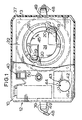
- Figures 1 and 2 show the portable device comprises a body base portion 11 of which is moulded from a suitable plastic material. Removably carried by the base 11 is a snap-on detachable cover 12 so that the rim flange 13 with a lower edge inwardly projecting retaining bead 14 is retainingly engageable with a complementary latching shoulder 15 at the inner side of a rabbet groove 17 which provides an upwardly facing shoulder on which the edge of the flange 13 seats.
- dynamo- electric means are provided inside 18 the device for generating tacit metronomic signal impulses, comprising in a preferred arrangement a balanced, co-operative pair of agitator electro-magnets 19 mounted in respective diametrically opposite spaced bosses 20 located at the rim of a cavity 21 defined within an integral thickened area 22 within the housing on the base member 11 and defining an opening from the housing.
- the transducer 24 is carried by a soundproof relatively soft, yieldably movable transmission pad 25 having a surface area facing inwardly and to which area is secured fixedly the outwardly facing surface of the member 24, while the arms 23 project from the inwardly margin of the facing surface of the member.
- the pad 25 of rubber or rubber-like elastic material desirably has an array of interspersed mode projections 27 providing a texture accentuated, an air cushioned or clap-proof face.
- the pad 25 has means for securing it to the base member 11, comprising a preferably continuous peripheral attachment flange 28 which is adapted to be firmly clamped against an annular frusto-conical shoulder 29 provided in annular outwardly opening groove cavity 30 concentric with the outwardly opening cavity 21 in the thickened base area 22.
- a clamping ring nut 31 is adapted to be threadedly engaged by means of threads 32 with base 11 within the annular cavity 30 and driven with its complementary frusto-conical clamping surface 33 against the pad flange 28 of the pad 25 to clamp it securely against the clamping shoulder 29.
- pulsing operation of the electro- magnets 19 is adapted to be effected by electrical means ( Figures 1, 2 and 4) comprising an electrical circuit 34, components of which may be carried on a circuit board 35 mounted as by means of a thin mounting panel 37 on the inside roof surface provided by the top of the cap 12.
- Means such as a pulse cycling transistor 38 and capacitor 38a (a digital circuitry may be alternately employed) are connected electrically to the electromagnets 19 and to a power source such as a battery 39.
- An on/off electrical switch 40 for the electrical circuit has suitable actuating means mounted conveniently on the cover 12.
- a pulse frequency or tempo control 41 in the circuit 34 is adapted to be adjusted as by means of a knob 42 located on the cover 12 and desirably provided with an indicator 43 for visualising adjustment relative to a tempo or pulse rate scale 44.
- the electro-magnets 19 are energised and de-energised with a frequency determined by the adjustment of the tempo control 41.
- the impulse signalling device arms 23 are drawn toward, but the sufficiently resilient pad 25 prevents contacting, the electromagnets and then released on de-energising of the electro-magnets.
- the device 10 may be carried in a garment pocket with the impulse transmitting pad 25 contiguous to the user's body.
- An attachment means 48, 49 is provided alternatively for attaching the device to the user's body.
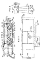
- the device 10 may provide with multiple circuit jack outlet 50 to which a lead connection 55 to slave unit 53 may be plugged in.
- the slave unit 53 is a stripped down version of device 10 that contains electro-magnets 19 and transmitter means 23, 24, 25 and it is powered by the signal pulsing component of a device 10 or an equivalent master signaller 54.
- Figure 3 depicts a multiple signalling where the equivalent signaller 54 is of increased capacity to accommodate the power demand from a large number of units 53.
- a DC adaptor 57 Connected to the master signaller 54 are a DC adaptor 57 to supply extra power when needed and an adaptor cord 63 leading to a conductor's baton 60 for effecting manual tempo signalling.
- Each pulse closes a synchronising relay switch 64, preferably of a silent kind that having a similar function as switch 62 in closing the pulsing circuit 65, which correspondingly actuate the solenoids 19' of the slave units synchronously, thereby a multiple signalling of a steady tempo is effected.
Landscapes
- Physics & Mathematics (AREA)
- General Physics & Mathematics (AREA)
- Percussion Or Vibration Massage (AREA)
- Electrophonic Musical Instruments (AREA)
- Circuits Of Receivers In General (AREA)
Claims (7)
Priority Applications (3)
| Application Number | Priority Date | Filing Date | Title |
|---|---|---|---|
| EP83307669A EP0145816B1 (de) | 1983-12-16 | 1983-12-16 | Metronomischer Signalgeber und Verfahren zur Tempoangabe |
| DE8383307669T DE3381873D1 (de) | 1983-12-16 | 1983-12-16 | Metronomischer signalgeber und verfahren zur tempoangabe. |
| AT83307669T ATE56286T1 (de) | 1983-12-16 | 1983-12-16 | Metronomischer signalgeber und verfahren zur tempoangabe. |
Applications Claiming Priority (1)
| Application Number | Priority Date | Filing Date | Title |
|---|---|---|---|
| EP83307669A EP0145816B1 (de) | 1983-12-16 | 1983-12-16 | Metronomischer Signalgeber und Verfahren zur Tempoangabe |
Publications (2)
| Publication Number | Publication Date |
|---|---|
| EP0145816A1 EP0145816A1 (de) | 1985-06-26 |
| EP0145816B1 true EP0145816B1 (de) | 1990-09-05 |
Family
ID=8191366
Family Applications (1)
| Application Number | Title | Priority Date | Filing Date |
|---|---|---|---|
| EP83307669A Expired EP0145816B1 (de) | 1983-12-16 | 1983-12-16 | Metronomischer Signalgeber und Verfahren zur Tempoangabe |
Country Status (3)
| Country | Link |
|---|---|
| EP (1) | EP0145816B1 (de) |
| AT (1) | ATE56286T1 (de) |
| DE (1) | DE3381873D1 (de) |
Family Cites Families (5)
| Publication number | Priority date | Publication date | Assignee | Title |
|---|---|---|---|---|
| CH220800A (de) * | 1940-12-06 | 1942-04-30 | Stalder Oskar | Armbandweckeruhr. |
| US2535809A (en) * | 1949-06-14 | 1950-12-26 | Otto H Niendorff | Timing device |
| DE2454621A1 (de) * | 1974-11-18 | 1976-05-20 | Geb Steinmassl Paula Poetschke | Verfahren zur ueberwachung, kontrolle und steigerung des koerperlichen trainings sowie taktgeber zur durchfuehrung des verfahrens |
| FR2493014A1 (fr) * | 1978-03-22 | 1982-04-30 | Stabler Edward | Procede et dispositif (polymetronome) pour les productions artistiques organisees sur le principe des structures de tempos differents simultanes (polytempie structurelle) |
| GB2121567B (en) * | 1982-04-27 | 1985-10-09 | Hsing Chen Shin | A metronomic signalling device and a method of metronomic and tempo signalling |
-
1983
- 1983-12-16 AT AT83307669T patent/ATE56286T1/de active
- 1983-12-16 EP EP83307669A patent/EP0145816B1/de not_active Expired
- 1983-12-16 DE DE8383307669T patent/DE3381873D1/de not_active Expired - Lifetime
Also Published As
| Publication number | Publication date |
|---|---|
| EP0145816A1 (de) | 1985-06-26 |
| ATE56286T1 (de) | 1990-09-15 |
| DE3381873D1 (de) | 1990-10-11 |
Similar Documents
| Publication | Publication Date | Title |
|---|---|---|
| US5790021A (en) | Remote control finder | |
| US7390955B2 (en) | Metronome with wireless transducer | |
| US4517564A (en) | Cordless remote control apparatus | |
| US3499361A (en) | Rhythm instrument | |
| US4437381A (en) | Metronomic signalling devices and method of tempo signalling | |
| US5883323A (en) | Sense of touch electronic tuner | |
| DE3576648D1 (de) | Beruhigungssauger mit musik. | |
| EP0145816B1 (de) | Metronomischer Signalgeber und Verfahren zur Tempoangabe | |
| US4233679A (en) | Adjustable piezoelectric transducer for a watch | |
| IE57091B1 (en) | Metronomic signalling device and method of tempo signalling | |
| GB2121567A (en) | A metronomic signalling device and a method of metronomic and tempo signalling | |
| US3263551A (en) | Electronic metronome | |
| JPH031628B2 (de) | ||
| US2553482A (en) | Electrical time reminder for various purposes | |
| US6962015B2 (en) | Sound actuated display device incorporating vibratory-rotary motion converter | |
| ES265211U (es) | Dispositivo de soporte para sujetar un transductor electroacustico en el oido. | |
| KR920003743B1 (ko) | 무음의 박자신호 발생장치와 무음의 박자신호를 발생시키는 방법 | |
| JPS6357749B2 (de) | ||
| JPS63108264U (de) | ||
| US2431574A (en) | Musical call signal telephone attachment | |
| GB553677A (en) | Improvements in or relating to microphones | |
| GB1087127A (en) | Frequency selective circuit and control apparatus including such circuit | |
| JP2000162329A (ja) | 時計体 | |
| CA1196507A (en) | Metronomic signalling devices and method of tempo signalling | |
| JPH0443064Y2 (de) |
Legal Events
| Date | Code | Title | Description |
|---|---|---|---|
| PUAI | Public reference made under article 153(3) epc to a published international application that has entered the european phase |
Free format text: ORIGINAL CODE: 0009012 |
|
| AK | Designated contracting states |
Designated state(s): AT CH DE FR IT LI NL SE |
|
| 17P | Request for examination filed |
Effective date: 19851220 |
|
| 17Q | First examination report despatched |
Effective date: 19870514 |
|
| GRAA | (expected) grant |
Free format text: ORIGINAL CODE: 0009210 |
|
| AK | Designated contracting states |
Kind code of ref document: B1 Designated state(s): AT CH DE FR IT LI NL SE |
|
| PG25 | Lapsed in a contracting state [announced via postgrant information from national office to epo] |
Ref country code: SE Effective date: 19900905 Ref country code: NL Effective date: 19900905 Ref country code: LI Effective date: 19900905 Ref country code: IT Free format text: LAPSE BECAUSE OF FAILURE TO SUBMIT A TRANSLATION OF THE DESCRIPTION OR TO PAY THE FEE WITHIN THE PRESCRIBED TIME-LIMIT;WARNING: LAPSES OF ITALIAN PATENTS WITH EFFECTIVE DATE BEFORE 2007 MAY HAVE OCCURRED AT ANY TIME BEFORE 2007. THE CORRECT EFFECTIVE DATE MAY BE DIFFERENT FROM THE ONE RECORDED. Effective date: 19900905 Ref country code: CH Effective date: 19900905 Ref country code: AT Effective date: 19900905 |
|
| REF | Corresponds to: |
Ref document number: 56286 Country of ref document: AT Date of ref document: 19900915 Kind code of ref document: T |
|
| ET | Fr: translation filed | ||
| REF | Corresponds to: |
Ref document number: 3381873 Country of ref document: DE Date of ref document: 19901011 |
|
| REG | Reference to a national code |
Ref country code: CH Ref legal event code: PL |
|
| PGFP | Annual fee paid to national office [announced via postgrant information from national office to epo] |
Ref country code: DE Payment date: 19910102 Year of fee payment: 8 |
|
| NLV1 | Nl: lapsed or annulled due to failure to fulfill the requirements of art. 29p and 29m of the patents act | ||
| PLBE | No opposition filed within time limit |
Free format text: ORIGINAL CODE: 0009261 |
|
| STAA | Information on the status of an ep patent application or granted ep patent |
Free format text: STATUS: NO OPPOSITION FILED WITHIN TIME LIMIT |
|
| 26N | No opposition filed | ||
| PG25 | Lapsed in a contracting state [announced via postgrant information from national office to epo] |
Ref country code: FR Effective date: 19910830 |
|
| REG | Reference to a national code |
Ref country code: FR Ref legal event code: ST |
|
| REG | Reference to a national code |
Ref country code: FR Ref legal event code: AR |
|
| PG25 | Lapsed in a contracting state [announced via postgrant information from national office to epo] |
Ref country code: DE Effective date: 19920901 |
|
| REG | Reference to a national code |
Ref country code: FR Ref legal event code: DE |