EP0145836A2 - Interféromètre pour mesurer la distance et méthode pour l'utiliser - Google Patents
Interféromètre pour mesurer la distance et méthode pour l'utiliser Download PDFInfo
- Publication number
- EP0145836A2 EP0145836A2 EP84108416A EP84108416A EP0145836A2 EP 0145836 A2 EP0145836 A2 EP 0145836A2 EP 84108416 A EP84108416 A EP 84108416A EP 84108416 A EP84108416 A EP 84108416A EP 0145836 A2 EP0145836 A2 EP 0145836A2
- Authority
- EP
- European Patent Office
- Prior art keywords
- wavefront
- interference pattern
- magnetic head
- head assembly
- reference surface
- Prior art date
- Legal status (The legal status is an assumption and is not a legal conclusion. Google has not performed a legal analysis and makes no representation as to the accuracy of the status listed.)
- Withdrawn
Links
Images


Classifications
-
- G—PHYSICS
- G11—INFORMATION STORAGE
- G11B—INFORMATION STORAGE BASED ON RELATIVE MOVEMENT BETWEEN RECORD CARRIER AND TRANSDUCER
- G11B5/00—Recording by magnetisation or demagnetisation of a record carrier; Reproducing by magnetic means; Record carriers therefor
- G11B5/48—Disposition or mounting of heads or head supports relative to record carriers ; arrangements of heads, e.g. for scanning the record carrier to increase the relative speed
- G11B5/58—Disposition or mounting of heads or head supports relative to record carriers ; arrangements of heads, e.g. for scanning the record carrier to increase the relative speed with provision for moving the head for the purpose of maintaining alignment of the head relative to the record carrier during transducing operation, e.g. to compensate for surface irregularities of the latter or for track following
- G11B5/60—Fluid-dynamic spacing of heads from record-carriers
- G11B5/6005—Specially adapted for spacing from a rotating disc using a fluid cushion
-
- G—PHYSICS
- G01—MEASURING; TESTING
- G01B—MEASURING LENGTH, THICKNESS OR SIMILAR LINEAR DIMENSIONS; MEASURING ANGLES; MEASURING AREAS; MEASURING IRREGULARITIES OF SURFACES OR CONTOURS
- G01B11/00—Measuring arrangements characterised by the use of optical techniques
- G01B11/14—Measuring arrangements characterised by the use of optical techniques for measuring distance or clearance between spaced objects or spaced apertures
-
- G—PHYSICS
- G01—MEASURING; TESTING
- G01B—MEASURING LENGTH, THICKNESS OR SIMILAR LINEAR DIMENSIONS; MEASURING ANGLES; MEASURING AREAS; MEASURING IRREGULARITIES OF SURFACES OR CONTOURS
- G01B9/00—Measuring instruments characterised by the use of optical techniques
- G01B9/02—Interferometers
- G01B9/02015—Interferometers characterised by the beam path configuration
- G01B9/02022—Interferometers characterised by the beam path configuration contacting one object by grazing incidence
-
- G—PHYSICS
- G01—MEASURING; TESTING
- G01B—MEASURING LENGTH, THICKNESS OR SIMILAR LINEAR DIMENSIONS; MEASURING ANGLES; MEASURING AREAS; MEASURING IRREGULARITIES OF SURFACES OR CONTOURS
- G01B2290/00—Aspects of interferometers not specifically covered by any group under G01B9/02
- G01B2290/70—Using polarization in the interferometer
Definitions
- the present invention relates to an apparatus and method for interferometrically measuring the absolute distance between a piano test surface and a piano reference surface which are in close proximity to each other. More particularly, the invention relates to apparatus which rapidly and accurately measures said absolute distance and which requires no physical contact with the surface under test.
- Interferometers are generally known for determining distances and the topography of a test surface; see, for example, C. Zanoni, "Interferometry," The Optical Industry and Systems Purchasing Directory, Book 2, pp. E-80 - E-82 (1983). Interferometry relies ultimately on the measurement of phase. In traditional interferometry, the measurement of phase is derived from the geometry of the fringe pattern.
- Phase measuring interferometry ascertains the phase at each point in the interference pattern by measuring the corresponding intensity variation as the overall phase is modulated.
- the phase must be modulated by 2 ⁇ in a precisely known way so as not to introduce errors in the measured intensities, see for example, J. H. Bruning, et al., "Digital Wavefront Measuring Interferometer for Testing Optical Surfaces and Lenses," Applied Optics, vol. 13, pp. 2693-2703 (1974); Gallagher, et al., U. S. Patent 3,694,088 issued September 26, 1972; N. Balasubramanian, U. S. Patent 4,225,240 issued September 30, 1980; M. Schaham, "Precision optical wavefront measurement," Proceedings SPIE, vol. 306, pp. 183-191 (1981); and H. Z. Hu, “Polarization heterodyne interferometry using a simple rotating analyzer. 1: Theory and error analysis,” Applied Optics, vol. 22, pp. 2052-2056 (1983).
- phase measuring interferometers the phase is modulated by a known amount by one of the following means: (1) mechanically moving an optical element of the interferometer with a piezoelectric transducer, (2) rotating a phase retardation plate in the interferometer, (3) use of either an acousto-optic, electro-optic, or similar device in the interferometer, and (4) variation of the incident angle, see for example, R. C. Moore, U. S. Patent 4,325,637 issued April 20, 1982.
- the prior-art fringe pattern and phase measuring interferometers are useful for many applications, they cannot be used for some measurements.
- the flying height is the distance between the magnetic head assembly's rails, also referred to as air bearing surfaces, and the surface of the rotating disk, see M. F. Garnier, et al., U. S. Patent 3,855,625 issued December 17, 1974.
- the flying height results from the aerodynamic effects produced by the disk's rotation and ranges from 0.1 to 0.25 micrometers.
- the topography As well as the angular orientation of the rails, or portions thereof, in order to assess the compliance of these parameters to the design specifications. It is desirable to measure the aforementioned parameters quickly and automatically with minimum operator intervention.
- the distance to be measured is nominally less than one-half of a wavelength of visible light, and the absolute distance must be measured.
- Prior-art apparatus and methods for measuring the flying height of a magnetic head assembly have included: (a) visual assessment of the color bands produced by
- white light interferometry (b) multiple wavelength interferometry, and (c) capacitive- type sensors.
- the prior-art optical techniques have generally measured the flying height of a magnetic head assembly using a rapidly rotating glass disk, one surface of which is a reference surface of an interferometer.
- White light interferometry suffers from a number of limitations; first, as the flying height gets below one-half a wavelength of light, i.e., approximately 0.3 micrometers, only limited and ambiguous information is available; second, it does not lend itself to automated operation for high through-put production testing. A single manufacturer typically produces 200,000 to 500,000 magnetic head assemblies per month.
- the multiple wavelength interferometry technique suffers from the same limitations.
- the capacitive sensor approach is suitable for some laboratory testing but requires that a capacitive transducer be added to the magnetic head assembly to be tested. For production testing this is neither practical nor cost effective. Furthermore, all of the aforementioned techniques provide poor spatial data sampling.
- Another object f the Invention is to provide an apparatus and method which precisely, automatically, and rapidly measures the flying height of a magnetic head assembly used in computer mass storage systems.
- Another object of the invention is to provide an apparatus and method which obviates the need to mechanically modulate an optical element of the interferometer cavity.
- Another object of the invention is to provide an apparatus and method in which the fringe contrast can always be adjusted to unity regardless of the reflectivities of the reference and test surfaces.
- Another object of the invention is to provide an apparatus and method in which the phase modulation is the same over the entire measurement aperture of the interferometer.
- I provide an optical interferometer system capable of measuring the absolute distance between a piano test surface and a piano reference surface which are in close proximity to each other comprising: (1) a source of a beam of coherent, single wavelength, linearly polarized energy, most preferably a laser; (2) means for varying the relative phase of the orthogonal polarization components of said beam; (3) means for spatially filtering and expanding the diameter of said beam; (4) means, most preferably a surface polarizer coating on a transparent substrate which is the reference surface in a Fizeau interferometer, for converting said expanded beam into a reference wavefront comprised of one of the polarization components and a measurement wavefront comprised of the other polarization component; (5) means, most preferably a polarizer, for producing an interference pattern between said reference wavefront and said measurement wavefront after it interacts with the test surface; (6) means, preferably a solid state array camera, for photosensing the radiant energy of said interference pattern over a two-dimensional array of points over a
- This invention includes a method to rapidly measure the flying height of a magnetic head assembly's rails over a rotating recording disk used in computer mass storage systems, in which (1) said recording disk is replaced by a transparent disk one surface of which is used as a reference surface in a Fizeau interferometer (2) said magnetic head assembly is placed against said reference surface (3) said transparent disk is rotated at the same speed used to rotate said recording disk so that said magnetic head assembly's rails assume the flying height assumed in actual use to become the test surface in said Fizeau interferometer (4) a beam of coherent, single wavelength, linearly polarized energy, most preferably a laser beam, is provided (5) the relative phase of the orthogonal polarization components of said beam is varied (6) said beam is spatially filtered and its diameter expanded (7) said expanded beam is converted into a reference wavefront comprised of one of the polarization components and a measurement wavefront comprised of the other polarization component, most preferably by the use of a surface polarizer coating on said reference surface, (8) after said measurement wavefront interacts
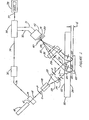
- Figure 1 depicts in schematic form an embodiment of the instant invention. While the apparatus has application for a wide range of radiation sources, the following description is taken by way of example with respect to an optical measuring system.
- the term "radiant energy” as used herein includes, but is not limited to, electromagnetic energy of all frequency ranges.
- a light source (10) most preferably a laser, provides coherent optical energy of single wavelength and linear polarization for the narrcw nearly collimated beam (12).
- Phase shifter (14) varies the relative phase of the orthogonal polarization components of beam (12) to produce beam (16). Phase shifter (14) could also be placed after the imaging system (36).
- phase shifter (14) may be any of the following: (a) a PZT driven corner cube or mirror (see, for example, B. E. Truax et al., "Laser Doppler Velocimeter for Velocity and Length Measurements of Moving Surfaces," Applied Opties, in publication), (b) a rotating, either continuously or discretely, half-wave phase retardation plate (see, for example, G. E. Sommargren, “Up/Down Frequency Shifter for Optical Heterodyne Interferometry," Journal of the Optical Society of America, vol. 65, p. 960 (1975)), (c) acousto-optic modulators (see, for example, N. A.
- the spatial filter-beam diverger (18) converts beam (16) into a diverging spherical wavefront (20).
- the spatial filter-beam diverger (18) uses an internal lens system and a small aperture located at the focus of the lens system to eliminate spurious beams and artifacts which are frequently found to accompany the principal output beam of a laser.
- Collimating lens (22) converts the diverging wavefront (20) to a plano wavefront (24).
- Piano wavefront (24) enters the optical element (50) at an angle 8 to the normal to surface (52) of element (50).
- Optical element (50) is made of a material which transmits the wavefront (26).
- Surfaces (52) and (54) are piano and parallel.
- Surface (54) is the reference surface for the Fizeau interferometer cavity and, thusly, must be made to a flatness tolerance consistent with the measurement tolerances desired.
- surface (52) has an antireflection coating so that essentially all of piano wavefront (24) is refracted onto element (50) as plano wavefront (26) and essentially none of wavefrcnt (24) is reflected by surface (52).
- Surface (54) of optical element (50) is coated so that it is a surface polarizer.
- a surface polarizer transmits the p polarization component of the wavefront (26) and reflects the s polarization component of the wavefront (26).
- the p label denotes the polarization component in the plane defined by the incident wavefront and the normal to the surface (54).
- the s label denotes the polarization component perpendicular to the plane defined by the incident wavefront and the normal to the surface (54).
- surface (54) is the reference surface for a Fizeau interferometer.
- Surface (54) converts wavefront (26) into a p polarization measurement wavefront (28) and an polarization reference wavefront (27).
- the measurement wavefront (28) is reflected by the test surface (62) of the article under test (60) to produce wavefront (30) which is refracted by surface (54) to produce wavefront (32).
- Wavefronts (27) and (32) emerge from element (50) as wavefronts (29) and (34) respectively.
- Imaging system (36) images the surface under test (62) onto the photosensitive surface of device (42), and in doing so converts wavefronts (29) and (34) into wavefronts (37) and (38), respectively.
- the optical path lengths, zr(x,y) and zt(x,y) are related by where d(x,y) is the distance between the surfaces (54) and (62) and is the angle of incidence.
- the phase shift can be written more explicitly as where ⁇ o is a constant offset due to the material properties and ⁇ 't is the linear phase modulation induced by the phase shifter (14) as shown in Fig. 2(a).
- Each wavefront i.e. (37) and (38) passes through the polarizer (40), which is oriented at an angle ⁇ with respect to the polarization of V r .
- the transmitted wavefronts are thus converted to the same polarization resulting in wavefronts (39) and (41) which form an interference pattern on photosensing device (42).
- Their combined amplitude is given by
- Device (42) can be a solid state camera with either CCD, CID, MOS or photodiode photosensitive elements in a two-dimensional array.
- Device (42) may alternatively be a linear array with either the interference pattern or the array scanned in a direction orthogonal to the length of the array for some applications.
- a modulated interference pattern is produced on the photosensitive surface of device (42).
- the details for aligning an interferometer, if required, are disclosed in Domencalli and Hunter, U.S. Patent 4,201,473 issued May 6, 1980.
- Output (70) provides the photosignals from the array of pixels of device (42) to the electronic processor (72).
- Electronic signals .(71) are provided by the processor (72) to control the device (42) if needed.
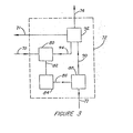
- the description of Fig. 3 provides the functional details of the electronic processor (72).
- the signal (74) from the electronic processor (72) is fed into the phase shifter driver (76).
- the output (79) of the phase shifter driver (76) is fed into the phase shifter (14).
- the resultant phase shift is shown in Fig. 2.
- T [(2 ⁇ )/m']
- each pixel integrates the fringe pattern intensity, I(x,y;t), to produce integral B(0), B(1), ..., B(N-1).
- B(k) is generally given by
- Figure 2 shows three phase modulation waveforms.
- Figure 2(a) shows the phase modulation waveform for a dynamic phase measurement method where the phase change is a linear, monotonic function.
- Figure 2(b) shows the phase modulation waveform for a dynamic phase measurement method where the phase change is a linear, periodic function.
- Figure 2(c) shows the phase modulation waveform for a static phase measurement method.
- Figure 3 depicts a schematic block diagram of the circuitry used in the electronic processor (72) in one embodiment of the invention.
- the output (70) of device (42) is fed into the analog-to-digital (A/D) converter (80) to provide the digital signal (82) which is stored in memory (84).
- the microprocessor (88) not only manipulates the data stored in memory (84), received via digital signal (86), but also provides and receives signals (90) with the measurement control unit (92) and provides an output signal (77) to the output device (78) which may be either a digital display or a printer, for example.
- the measurement control unit (92) provides (a) a waveform signal (74) to the phase shifter driver (76); (b) a clock signal (71) to the device (42); and (c) a synchronization signal (94) to the A/D converter (80).
- Figure 4 depicts in schematic form an embodiment of the instant invention for the measurement of the flying height of a magnetic head assembly.
- Figure 4(a) is a partial side view and Fig. 4(b) is a top view, partially schematic.
- the glass disk (50) is mounted on precision bearing (106). Motor (108) rotates the glass disk as shown.
- the magnetic head assembly (100) is supported from the base (104) by a flexure element (102).
- the unit (110) is comprised of the optical/mechanical elements in Fig. 1 of the instant invention.
- the measurement wavefront (24) illuminates the reference surface (54) of the glass disk (50) and the rails (112) and (114), see Fig. 4(b) of the magnetic head assembly (100).
- the function of elements (70), (71), (72), (77), and (78) are described in the description of Fig. 1.
- Fig. 4(b) a top view, partially schematic, is depicted to show, not to scale, the measurement arrangement.
- the coherence length of the radiant energy can readily be so modified without departing from the scope of the invention using a suitable device, such as a rotating ground glass, suitably placed in the interferometer.
- a suitable device such as a rotating ground glass
- the coherence length of the radiant energy can be reduced or destroyed either before it enters the interferometer cavity, e.g., see Moore, op. cit., or after the reference and measurement wavefronts are combined to form an interference pattern, e.g. see Domeniealli and Hunter, op. cit.
Landscapes
- Physics & Mathematics (AREA)
- General Physics & Mathematics (AREA)
- Instruments For Measurement Of Length By Optical Means (AREA)
- Length Measuring Devices By Optical Means (AREA)
Applications Claiming Priority (2)
| Application Number | Priority Date | Filing Date | Title |
|---|---|---|---|
| US548248 | 1983-11-03 | ||
| US06/548,248 US4606638A (en) | 1983-11-03 | 1983-11-03 | Distance measuring interferometer and method of use |
Publications (2)
| Publication Number | Publication Date |
|---|---|
| EP0145836A2 true EP0145836A2 (fr) | 1985-06-26 |
| EP0145836A3 EP0145836A3 (fr) | 1988-08-03 |
Family
ID=24188012
Family Applications (1)
| Application Number | Title | Priority Date | Filing Date |
|---|---|---|---|
| EP84108416A Withdrawn EP0145836A3 (fr) | 1983-11-03 | 1984-07-17 | Interféromètre pour mesurer la distance et méthode pour l'utiliser |
Country Status (3)
| Country | Link |
|---|---|
| US (1) | US4606638A (fr) |
| EP (1) | EP0145836A3 (fr) |
| JP (1) | JPS60123704A (fr) |
Cited By (5)
| Publication number | Priority date | Publication date | Assignee | Title |
|---|---|---|---|---|
| EP0313775A1 (fr) * | 1987-10-08 | 1989-05-03 | Siemens Aktiengesellschaft | Système de mesure sans contact des caractéristiques d'exactitude, particulièrement pour les robots industriels |
| EP0410187A1 (fr) * | 1989-07-24 | 1991-01-30 | Becton, Dickinson and Company | Mesurage d'une fente entre un tube et un flotteur |
| US5909282A (en) * | 1996-05-31 | 1999-06-01 | Tropel Corporation | Interferometer for measuring thickness variations of semiconductor wafers |
| US7921718B2 (en) | 2001-04-16 | 2011-04-12 | Zevex, Inc. | Optical pressure monitoring system |
| CN106052561A (zh) * | 2016-08-05 | 2016-10-26 | 京东方科技集团股份有限公司 | 位置传感器以及包括其的运送装置和利用其进行位置修正的方法 |
Families Citing this family (66)
| Publication number | Priority date | Publication date | Assignee | Title |
|---|---|---|---|---|
| US5121987A (en) * | 1989-03-02 | 1992-06-16 | Honeywell Inc. | Method and apparatus for measuring coefficient of thermal expansion |
| US4989980A (en) * | 1989-03-02 | 1991-02-05 | Honeywell Inc. | Method and apparatus for measuring coefficient of thermal expansion |
| JP2533664B2 (ja) * | 1990-01-17 | 1996-09-11 | 株式会社日立製作所 | 磁気記録装置 |
| US5218424A (en) * | 1991-03-19 | 1993-06-08 | Zygo Corporation | Flying height and topography measuring interferometer |
| US5374991A (en) * | 1991-03-29 | 1994-12-20 | Gradient Lens Corporation | Compact distance measuring interferometer |
| US5327216A (en) * | 1992-09-18 | 1994-07-05 | Shell Oil Company | Apparatus for remote seismic sensing of array signals using side-by-side retroreflectors |
| US5317383A (en) * | 1992-09-18 | 1994-05-31 | Shell Oil Company | Array retroreflector apparatus for remote seismic sensing |
| US5289434A (en) * | 1992-09-18 | 1994-02-22 | Shell Oil Company | Retroreflector apparatus for remote seismic sensing |
| US5430537A (en) * | 1993-09-03 | 1995-07-04 | Dynamics Research Corporation | Light beam distance encoder |
| US5473434A (en) * | 1994-05-16 | 1995-12-05 | Zygo Corporation | Phase shifting interferometer and method for surface topography measurement |
| US5457395A (en) * | 1994-07-18 | 1995-10-10 | Ford Motor Company | System and apparatus for measuring gaps between non-parallel surfaces |
| US5600441A (en) * | 1995-01-31 | 1997-02-04 | Zygo Corporation | Interferometer and method for measuring the distance of an object surface with respect to the surface of a rotating disk |
| US5557399A (en) * | 1995-03-22 | 1996-09-17 | Zygo Corporation | Optical gap measuring apparatus and method |
| CN1131741A (zh) * | 1995-03-22 | 1996-09-25 | 载歌公司 | 光学间隙测量装置和方法 |
| US5953125A (en) * | 1995-09-01 | 1999-09-14 | Zygo Corporation | Optical gap measuring apparatus and method |
| US5831733A (en) * | 1996-02-28 | 1998-11-03 | Zygo Corporation | Apparatus and methods for measuring gaps while compensating for birefringence effects in the measurement path |
| US5644562A (en) * | 1996-02-28 | 1997-07-01 | Zygo Corporation | Method and apparatus for measuring and compensating birefringence in rotating disks |
| US20030145353A1 (en) * | 1997-05-07 | 2003-07-31 | Lightner Jonathan E. | Starch biosynthetic enzymes |
| DE19962078B4 (de) * | 1998-12-23 | 2010-03-18 | CiS Institut für Mikrosensorik gGmbH | Verfahren und Vorrichtung zur interferentiellen Abstandsmessung |
| US6271924B1 (en) | 1998-12-29 | 2001-08-07 | Bryan Kok Ann Ngoi | Noncontact acoustic optic scanning laser vibrometer for determining the difference between an object and a reference surface |
| US6184993B1 (en) * | 1999-02-09 | 2001-02-06 | Phase Metrics, Inc. | Apparatus for measuring a small gap using a Savart plate |
| US6184992B1 (en) * | 1999-02-09 | 2001-02-06 | Phase Metrics, Inc. | Apparatus and method for measuring flying height and a real index of refraction |
| US6710881B1 (en) | 1999-09-28 | 2004-03-23 | Nanyang Technological University | Heterodyne interferometry for small spacing measurement |
| US6624892B1 (en) | 2000-06-01 | 2003-09-23 | Seagate Technolgy Llc | Method and apparatus for fly height testing using light emitting diodes |
| US6847452B2 (en) * | 2001-08-02 | 2005-01-25 | Zygo Corporation | Passive zero shear interferometers |
| EP1419361A1 (fr) * | 2001-08-23 | 2004-05-19 | Zygo Corporation | Interferometre dynamique commandant la direction du faisceau d'entree |
| US6912054B2 (en) * | 2001-08-28 | 2005-06-28 | Zygo Corporation | Interferometric stage system |
| US6680811B2 (en) * | 2001-10-09 | 2004-01-20 | International Business Machines Corporation | System and method for enhancing load/unload performance of low-flying heads in a disk drive |
| WO2003036225A1 (fr) * | 2001-10-26 | 2003-05-01 | University Of Rochester | Methode de detection biomoleculaire et systeme associe |
| US7057739B2 (en) * | 2002-02-12 | 2006-06-06 | Zygo Corporation | Separated beam multiple degree of freedom interferometer |
| WO2003069286A2 (fr) * | 2002-02-12 | 2003-08-21 | Zygo Corporation | Procede et appareil pour mesurer des erreurs de capteur optique dans des systemes d'interferometrie |
| US7262860B2 (en) * | 2002-07-29 | 2007-08-28 | Zygo Corporation | Compensation for errors in off-axis interferometric measurements |
| US7274462B2 (en) * | 2002-09-09 | 2007-09-25 | Zygo Corporation | In SITU measurement and compensation of errors due to imperfections in interferometer optics in displacement measuring interferometry systems |
| US7321432B2 (en) * | 2002-09-09 | 2008-01-22 | Zygo Corporation | Measurement and compensation of errors in interferometers |
| EP1583934A1 (fr) * | 2002-12-12 | 2005-10-12 | Zygo Corporation | Correction en cours de fabrication de deformations de miroirs de platine lors d'un cycle d'exposition photolithographique |
| US7327465B2 (en) * | 2003-06-19 | 2008-02-05 | Zygo Corporation | Compensation for effects of beam misalignments in interferometer metrology systems |
| US7286240B2 (en) * | 2003-06-19 | 2007-10-23 | Zygo Corporation | Compensation for geometric effects of beam misalignments in plane mirror interferometer metrology systems |
| US7283248B2 (en) * | 2004-01-06 | 2007-10-16 | Zygo Corporation | Multi-axis interferometers and methods and systems using multi-axis interferometers |
| US7310152B2 (en) * | 2004-03-03 | 2007-12-18 | Zygo Corporation | Interferometer assemblies having reduced cyclic errors and system using the interferometer assemblies |
| US7305158B2 (en) * | 2004-04-15 | 2007-12-04 | Davidson Instruments Inc. | Interferometric signal conditioner for measurement of absolute static displacements and dynamic displacements of a Fabry-Perot interferometer |
| US7492463B2 (en) * | 2004-04-15 | 2009-02-17 | Davidson Instruments Inc. | Method and apparatus for continuous readout of Fabry-Perot fiber optic sensor |
| JP2007534941A (ja) * | 2004-04-22 | 2007-11-29 | ザイゴ コーポレーション | 光学干渉計システムおよび光学干渉計システムを用いる方法 |
| US7375823B2 (en) * | 2004-04-22 | 2008-05-20 | Zygo Corporation | Interferometry systems and methods of using interferometry systems |
| WO2006014406A2 (fr) | 2004-06-30 | 2006-02-09 | Zygo Corporation | Ensembles optiques interferometriques et systemes les comprenant |
| US7489407B2 (en) * | 2004-10-06 | 2009-02-10 | Zygo Corporation | Error correction in interferometry systems |
| DE502004011107D1 (de) * | 2004-10-13 | 2010-06-10 | Leica Geosystems Ag | Verfahren und Messgerät zur Messung eines Absolutdistanzwertes |
| US7864329B2 (en) | 2004-12-21 | 2011-01-04 | Halliburton Energy Services, Inc. | Fiber optic sensor system having circulators, Bragg gratings and couplers |
| US7835598B2 (en) | 2004-12-21 | 2010-11-16 | Halliburton Energy Services, Inc. | Multi-channel array processor |
| EP1869737B1 (fr) | 2005-03-16 | 2021-05-12 | Davidson Instruments, Inc. | Capteur fabry-perot haute intensite |
| US7433049B2 (en) * | 2005-03-18 | 2008-10-07 | Zygo Corporation | Multi-axis interferometer with procedure and data processing for mirror mapping |
| JP4869656B2 (ja) * | 2005-08-08 | 2012-02-08 | 株式会社ミツトヨ | 干渉計 |
| WO2007033069A2 (fr) | 2005-09-13 | 2007-03-22 | Davidson Instruments Inc. | Algorithme de poursuite pour processeur de signal a reseau lineaire a schemas de correlation croisee de fabry-perot et son procede d'utilisation |
| US7551294B2 (en) * | 2005-09-16 | 2009-06-23 | University Of Rochester | System and method for brewster angle straddle interferometry |
| US7830528B2 (en) * | 2005-12-14 | 2010-11-09 | Koh Young Technology, Inc. | 3D image measuring apparatus and method thereof |
| US7684051B2 (en) * | 2006-04-18 | 2010-03-23 | Halliburton Energy Services, Inc. | Fiber optic seismic sensor based on MEMS cantilever |
| US7743661B2 (en) | 2006-04-26 | 2010-06-29 | Halliburton Energy Services, Inc. | Fiber optic MEMS seismic sensor with mass supported by hinged beams |
| US8115937B2 (en) | 2006-08-16 | 2012-02-14 | Davidson Instruments | Methods and apparatus for measuring multiple Fabry-Perot gaps |
| US7787128B2 (en) | 2007-01-24 | 2010-08-31 | Halliburton Energy Services, Inc. | Transducer for measuring environmental parameters |
| US8422112B2 (en) * | 2008-02-04 | 2013-04-16 | Industrial Technology Research Institute | Display system |
| JP5268425B2 (ja) * | 2008-05-16 | 2013-08-21 | キヤノン株式会社 | 表面形状測定装置及び露光装置 |
| DE102011111900A1 (de) * | 2011-08-30 | 2013-02-28 | Dr. Johannes Heidenhain Gmbh | Vorrichtung zur interferometrischen Abstandsbestimmung |
| EP2653884A1 (fr) * | 2012-04-16 | 2013-10-23 | Leica Geosystems AG | Dispositif électro-optique de mesure de distance |
| DE102013221898A1 (de) * | 2013-10-29 | 2015-04-30 | Dr. Johannes Heidenhain Gmbh | Vorrichtung zur Positionsbestimmung |
| US11262191B1 (en) | 2018-07-12 | 2022-03-01 | Onto Innovation Inc. | On-axis dynamic interferometer and optical imaging systems employing the same |
| US12216051B2 (en) | 2022-01-21 | 2025-02-04 | Onto Innovation Inc. | Dynamic phase-shift interferometer utilizing a synchronous optical frequency-shift |
| JP2025540911A (ja) * | 2022-11-15 | 2025-12-17 | シーネラ テクノロジーズ リミテッド | イメージングシステムおよび方法 |
Family Cites Families (9)
| Publication number | Priority date | Publication date | Assignee | Title |
|---|---|---|---|---|
| US3695767A (en) * | 1970-11-18 | 1972-10-03 | Burroughs Corp | Apparatus for measuring magnetic head angle of a magnetic disc file |
| US3694088A (en) * | 1971-01-25 | 1972-09-26 | Bell Telephone Labor Inc | Wavefront measurement |
| US3855625A (en) * | 1973-12-19 | 1974-12-17 | Ibm | Magnetic head slider assembly |
| US4188122A (en) * | 1978-03-27 | 1980-02-12 | Rockwell International Corporation | Interferometer |
| US4201473A (en) * | 1978-04-21 | 1980-05-06 | Zygo Corporation | Optical interferometer system with CCTV camera for measuring a wide range of aperture sizes |
| US4225240A (en) * | 1978-06-05 | 1980-09-30 | Balasubramanian N | Method and system for determining interferometric optical path length difference |
| DE2851750B1 (de) * | 1978-11-30 | 1980-03-06 | Ibm Deutschland | Verfahren und Vorrichtung zur Messung der Ebenheit der Rauhigkeit oder des Kruemmungsradius einer Messflaeche |
| JPS56103303A (en) * | 1980-01-21 | 1981-08-18 | Hitachi Ltd | Optical measuring method for micro-gap |
| US4325637A (en) * | 1980-06-02 | 1982-04-20 | Tropel, Inc. | Phase modulation of grazing incidence interferometer |
-
1983
- 1983-11-03 US US06/548,248 patent/US4606638A/en not_active Expired - Fee Related
-
1984
- 1984-07-17 EP EP84108416A patent/EP0145836A3/fr not_active Withdrawn
- 1984-10-29 JP JP59227638A patent/JPS60123704A/ja active Granted
Cited By (8)
| Publication number | Priority date | Publication date | Assignee | Title |
|---|---|---|---|---|
| EP0313775A1 (fr) * | 1987-10-08 | 1989-05-03 | Siemens Aktiengesellschaft | Système de mesure sans contact des caractéristiques d'exactitude, particulièrement pour les robots industriels |
| US4880992A (en) * | 1987-10-08 | 1989-11-14 | Siemens Aktiengesellschaft | Non-contacting measuring system for precision characteristics, particularly of industrial robots |
| EP0410187A1 (fr) * | 1989-07-24 | 1991-01-30 | Becton, Dickinson and Company | Mesurage d'une fente entre un tube et un flotteur |
| US5909282A (en) * | 1996-05-31 | 1999-06-01 | Tropel Corporation | Interferometer for measuring thickness variations of semiconductor wafers |
| US7921718B2 (en) | 2001-04-16 | 2011-04-12 | Zevex, Inc. | Optical pressure monitoring system |
| CN106052561A (zh) * | 2016-08-05 | 2016-10-26 | 京东方科技集团股份有限公司 | 位置传感器以及包括其的运送装置和利用其进行位置修正的方法 |
| CN106052561B (zh) * | 2016-08-05 | 2019-07-09 | 京东方科技集团股份有限公司 | 位置传感器以及包括其的运送装置和利用其进行位置修正的方法 |
| US10571258B2 (en) | 2016-08-05 | 2020-02-25 | Boe Technology Group Co., Ltd. | Position sensor, conveying device comprising the same, and method for position correction by using the same |
Also Published As
| Publication number | Publication date |
|---|---|
| JPS60123704A (ja) | 1985-07-02 |
| EP0145836A3 (fr) | 1988-08-03 |
| JPH0431043B2 (fr) | 1992-05-25 |
| US4606638A (en) | 1986-08-19 |
Similar Documents
| Publication | Publication Date | Title |
|---|---|---|
| US4606638A (en) | Distance measuring interferometer and method of use | |
| US4869593A (en) | Interferometric surface profiler | |
| US4594003A (en) | Interferometric wavefront measurement | |
| US4948253A (en) | Interferometric surface profiler for spherical surfaces | |
| Tiziani | Optical methods for precision measurements: An invited paper | |
| US4422764A (en) | Interferometer apparatus for microtopography | |
| US4732483A (en) | Interferometric surface profiler | |
| US6822745B2 (en) | Optical systems for measuring form and geometric dimensions of precision engineered parts | |
| Wykes | Use of electronic speckle pattern interferometry (ESPI) in the measurement of static and dynamic surface displacements | |
| US5218424A (en) | Flying height and topography measuring interferometer | |
| Koliopoulos | Interferometric optical phase measurement techniques | |
| US4432239A (en) | Apparatus for measuring deformation | |
| US4139304A (en) | Methods and apparatus for measuring variations in distance to a surface | |
| US4340304A (en) | Interferometric method and system | |
| WO2013134966A1 (fr) | Interféromètre à balayage des longueurs d'ondes pour mesures d'asphéricité, et procédé d'application correspondant | |
| JP2006515925A (ja) | 共通経路周波数走査型干渉計 | |
| US3767307A (en) | Real time interferometer | |
| Kaufmann | Automatic fringe analysis procedures in speckle metrology | |
| US4347000A (en) | Interferometric system | |
| EP0731335B1 (fr) | Appareil et méthode pour tester de façon non-déstructive des matériaux illuminés par de la lumière cohérente | |
| Hariharan | Interferometric metrology: current trends and future prospects | |
| JPH02259510A (ja) | 面形状等測定方法及び装置 | |
| Butters | Speckle pattern interferometry using video techniques | |
| US5120133A (en) | Interferometer with two phase-conjugate mirrors | |
| JPS63128211A (ja) | スペ−シング測定方法 |
Legal Events
| Date | Code | Title | Description |
|---|---|---|---|
| PUAI | Public reference made under article 153(3) epc to a published international application that has entered the european phase |
Free format text: ORIGINAL CODE: 0009012 |
|
| AK | Designated contracting states |
Designated state(s): DE FR GB |
|
| 17P | Request for examination filed |
Effective date: 19850703 |
|
| PUAL | Search report despatched |
Free format text: ORIGINAL CODE: 0009013 |
|
| AK | Designated contracting states |
Kind code of ref document: A3 Designated state(s): DE FR GB |
|
| RHK1 | Main classification (correction) |
Ipc: G01B 9/02 |
|
| STAA | Information on the status of an ep patent application or granted ep patent |
Free format text: STATUS: THE APPLICATION IS DEEMED TO BE WITHDRAWN |
|
| 18D | Application deemed to be withdrawn |
Effective date: 19890202 |
|
| RIN1 | Information on inventor provided before grant (corrected) |
Inventor name: SOMMARGREN, GARY E. |