EP0146161A2 - Regelbares Schlauchanschlussventil für Atemluftanfuhr - Google Patents
Regelbares Schlauchanschlussventil für Atemluftanfuhr Download PDFInfo
- Publication number
- EP0146161A2 EP0146161A2 EP84201661A EP84201661A EP0146161A2 EP 0146161 A2 EP0146161 A2 EP 0146161A2 EP 84201661 A EP84201661 A EP 84201661A EP 84201661 A EP84201661 A EP 84201661A EP 0146161 A2 EP0146161 A2 EP 0146161A2
- Authority
- EP
- European Patent Office
- Prior art keywords
- wall
- connection valve
- adjustable connection
- passage
- valve according
- Prior art date
- Legal status (The legal status is an assumption and is not a legal conclusion. Google has not performed a legal analysis and makes no representation as to the accuracy of the status listed.)
- Granted
Links
- 230000000241 respiratory effect Effects 0.000 claims description 2
- 230000000903 blocking effect Effects 0.000 claims 1
- 238000006073 displacement reaction Methods 0.000 claims 1
- 238000005192 partition Methods 0.000 abstract 2
- 230000029058 respiratory gaseous exchange Effects 0.000 abstract 1
- 239000007789 gas Substances 0.000 description 11
- 238000004026 adhesive bonding Methods 0.000 description 1
- 230000015572 biosynthetic process Effects 0.000 description 1
- 230000008878 coupling Effects 0.000 description 1
- 238000010168 coupling process Methods 0.000 description 1
- 238000005859 coupling reaction Methods 0.000 description 1
Images

Classifications
-
- A—HUMAN NECESSITIES
- A62—LIFE-SAVING; FIRE-FIGHTING
- A62B—DEVICES, APPARATUS OR METHODS FOR LIFE-SAVING
- A62B9/00—Component parts for respiratory or breathing apparatus
- A62B9/02—Valves
Definitions
- a known adjustable connection valve for the supply of respiratory air essentially consists of four elements, namely a first element, to which is connected a cap, with which the filter can cooperate in an airtight manner. a gas mask or other similar device; a second element, to which is connected an air supply pipe and which, at its free end, is closed and is provided with at least one passage, this second element being capable of being displaced relative to the first element; a third element suitable for opening or closing the valve and also having an air passage opening; and a fourth element comprising a spring tending to maintain the valve in its closed position or to bring it to this position; a special feature of the connection valve according to this main patent consisting in that the air passage openings, which must be able to cooperate mutually in an adjustable manner to ensure the supply of air or connected filter of the gas mask or another similar device extend radially in tubular elements.
- the present invention relates to improvements, of the aforementioned valve, consisting mainly in that the aforesaid air passage openings are arranged axially in various mutually cooperating elements of the coupling sub-valve, which presents, inter alia, the advantage of a significant reduction in resistance by the subpape the passage of air, with, consequently, a significant reduction in the risk of formation of depression in the gas mask, as well as the advantage of a net increase in the adjustment range of the valve.
- the adjustable connection valve having the above-mentioned and other characteristics consists essentially of four elements for this purpose, namely a first element, to which is connected a cap, with which it can cooperate, in an airtight manner , the filter of a gas mask or other similar device; a second element to which is connected an air supply pipe and which, at its free end is closed and is provided with at least one passage, this second element being capable of being displaced relative to the first element; a third element suitable for opening or closing the valve and also having an air passage opening; and a fourth element comprising a spring tending to maintain the valve in its closed position or to bring it to this position; characterized in that a fifth element is provided between the first and the second element, having at least one air passage opening, capable of being displaced relative to an air passage opening of the first element, in that which the second element and the third element element together form a whole and in that the passage of air through the valve is an almost completely axial passage.
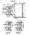
- the adjustable connection valve 1, illustrated by the appended figures, essentially consists of five elements, of which the first element 2, on which the cap 3 is mounted in an airtight manner, consists of two concentric parts 4 and 5 , joined, at one of their ends, by a wall 6, provided with two diametrically opposite passage openings 7.
- This element 2 is, in the present embodiment of the invention, extended by a fifth element 8, consisting essentially of a cylindrical part 9, the outside diameter of which is equal to that of element 2, and of part 10, concentric with this part 9 and sliding in part 5 of element 2.
- These two parts 9 and 10 are mutually connected by a wall 11 provided with two diametrically opposite passage openings 12, each having a narrow part 13 and a wider part 14.
- the two elements 2 and 8 can be angularly offset one relative to the other and are, preferably rence, provided with a snap-in system intended to lock them reciprocally in determined positions.
- the wall 11 is, for example, provided with notches 15, with which a ball 16 cooperates urged by a spring 17.
- the second element 18 of the connection valve 1 is in the form of a wall 19, capable of sliding in the above element 8 and mounted on a tubular part 20, to which can be fixed, on one side of the wall 19 , suitably, an air hose 21, while, on the other side of the wall 19, there are openings 22 in the tubular part 20.
- the end of the latter, located beyond the openings 22, is provided with an end wall 23, on which is fixed the wall 24 of the third element 25, which is appropriately fixed, for example by gluing, to the second element 18 and is thus capable of moving with this element 18 relative to the first element 2, the above-mentioned wall 24 being provided with openings 26.
- the fourth element is provided, in the form of a spring 26.
- the valve is closed in the position shown in FIG. 1.
- the wall 19 of the element 18 applies to the wall 11 of the element 8 so as to close the openings 12, while the part of the element 18, provided with the openings 22, applies to the part 10 of the element 8, so as to also avoid the passage of air through these openings.
- the third element 25 and, consequently, also the second element 18 move relative to the second element 18 and to the fifth element 8, respectively, so as to disengage the openings 22 from the part 10 of the element 8 and to move the wall 19 of the element 18 away from the openings 12, all of this so as to allow the free passage of air, brought by the flexible 21, by the tubular part 20 and the openings 22, 12, 7 and 26 towards the filter 28.
- the spring 27 thus compressed ensures, when the filter 28 is removed from the cap 3, the automatic reclosing of the valve 1.
- the element 8 With a view to adjusting the air flow rate passing through the filter 28 of the gas mask 29, the element 8 can be rotated relative to the element 2, so that the passage openings 7 more or less cover the openings of passage 12 of wall 11.
- the free passage section can vary between a minimum value, determined by stops 30-31 (fig. 4 and 6), and a maximum value.
- valves of the type to which the present invention relates are used to connect gas masks or other similar devices to a common air supply pipe, for example, in workshops giving off harmful products (gases or vapors) , in vehicles intended to cross infested areas, etc., all of this so that the persons concerned wearing a gas mask can at any time be connected to a cap 3 so as to increase the autonomy of the gas mask.
Landscapes
- Health & Medical Sciences (AREA)
- Pulmonology (AREA)
- General Health & Medical Sciences (AREA)
- Business, Economics & Management (AREA)
- Emergency Management (AREA)
- Respiratory Apparatuses And Protective Means (AREA)
- Compressor (AREA)
- Self-Closing Valves And Venting Or Aerating Valves (AREA)
- Feeding, Discharge, Calcimining, Fusing, And Gas-Generation Devices (AREA)
Priority Applications (1)
| Application Number | Priority Date | Filing Date | Title |
|---|---|---|---|
| AT84201661T ATE49895T1 (de) | 1983-11-21 | 1984-11-19 | Regelbares schlauchanschlussventil fuer atemluftanfuhr. |
Applications Claiming Priority (2)
| Application Number | Priority Date | Filing Date | Title |
|---|---|---|---|
| BE2/60262A BE898263R (nl) | 1983-11-21 | 1983-11-21 | Regelbaar aansluitventiel voor ademluchttoevoer. |
| BE2060262 | 1983-11-21 |
Publications (3)
| Publication Number | Publication Date |
|---|---|
| EP0146161A2 true EP0146161A2 (de) | 1985-06-26 |
| EP0146161A3 EP0146161A3 (en) | 1986-02-12 |
| EP0146161B1 EP0146161B1 (de) | 1990-01-31 |
Family
ID=3865662
Family Applications (1)
| Application Number | Title | Priority Date | Filing Date |
|---|---|---|---|
| EP84201661A Expired - Lifetime EP0146161B1 (de) | 1983-11-21 | 1984-11-19 | Regelbares Schlauchanschlussventil für Atemluftanfuhr |
Country Status (3)
| Country | Link |
|---|---|
| EP (1) | EP0146161B1 (de) |
| AT (1) | ATE49895T1 (de) |
| DE (1) | DE3481173D1 (de) |
Cited By (5)
| Publication number | Priority date | Publication date | Assignee | Title |
|---|---|---|---|---|
| GB2221844A (en) * | 1988-07-19 | 1990-02-21 | Protector Safety Ltd | Respirator filter |
| US4903694A (en) * | 1988-03-09 | 1990-02-27 | J. Blaschke Pumpen-Filteranlagen | Ventilating apparatus for a protective suit |
| USH1361H (en) * | 1992-05-06 | 1994-10-04 | The United States Of America As Represented By The Secretary Of The Army | Softshell protective mask |
| WO2001005348A1 (en) * | 1999-07-16 | 2001-01-25 | Inteledatics, Inc. | Isolation apparatus |
| CN113521583A (zh) * | 2021-08-27 | 2021-10-22 | 姜玫 | 一种消防过滤式自救呼吸器 |
Family Cites Families (4)
| Publication number | Priority date | Publication date | Assignee | Title |
|---|---|---|---|---|
| GB231061A (en) * | 1924-07-17 | 1925-03-26 | Curtis Mordaunt Shipley | Improvements in coupling valve |
| AT321048B (de) * | 1972-05-09 | 1975-03-10 | Paula Duda | Drosselrückschlagventil |
| FR2511252A1 (fr) * | 1982-04-02 | 1983-02-18 | Fenzy Sa | Embout pour appareil respiratoire pour le raccordement du masque a une bouteille de gaz respiratoire |
| BE895415A (en) * | 1982-12-21 | 1983-04-15 | Vandeputte Gilbert | Breathing mask air filter valve - couplable to air line then opening valve to increase filter life when mask user stationary |
-
1984
- 1984-11-19 EP EP84201661A patent/EP0146161B1/de not_active Expired - Lifetime
- 1984-11-19 AT AT84201661T patent/ATE49895T1/de active
- 1984-11-19 DE DE8484201661T patent/DE3481173D1/de not_active Expired - Lifetime
Cited By (6)
| Publication number | Priority date | Publication date | Assignee | Title |
|---|---|---|---|---|
| US4903694A (en) * | 1988-03-09 | 1990-02-27 | J. Blaschke Pumpen-Filteranlagen | Ventilating apparatus for a protective suit |
| GB2221844A (en) * | 1988-07-19 | 1990-02-21 | Protector Safety Ltd | Respirator filter |
| GB2221844B (en) * | 1988-07-19 | 1992-03-04 | Protector Safety Ltd | Respirator filters |
| USH1361H (en) * | 1992-05-06 | 1994-10-04 | The United States Of America As Represented By The Secretary Of The Army | Softshell protective mask |
| WO2001005348A1 (en) * | 1999-07-16 | 2001-01-25 | Inteledatics, Inc. | Isolation apparatus |
| CN113521583A (zh) * | 2021-08-27 | 2021-10-22 | 姜玫 | 一种消防过滤式自救呼吸器 |
Also Published As
| Publication number | Publication date |
|---|---|
| EP0146161B1 (de) | 1990-01-31 |
| EP0146161A3 (en) | 1986-02-12 |
| ATE49895T1 (de) | 1990-02-15 |
| DE3481173D1 (de) | 1990-03-08 |
Similar Documents
| Publication | Publication Date | Title |
|---|---|---|
| FR2715451A3 (fr) | Vanne de commande d'écoulement à commande magnétique. | |
| FR2517014A1 (fr) | Ensemble a valve pour l'ecoulement commande d'un liquide accumule dans un recipient | |
| EP1321241A1 (de) | Druckgaspatrone für Befestigungsgerät und Adapter für Verbindungsmuffe | |
| EP0146161B1 (de) | Regelbares Schlauchanschlussventil für Atemluftanfuhr | |
| EP0519800A1 (de) | Vorrichtung zum Montieren zweier Leitungen auf zwei benachbarte Öffnungen von einer Endkammer eines Wärmetauschers | |
| EP0513712B1 (de) | Gerät für Atemübungen | |
| FR2731071A1 (fr) | Indicateur de pression differentielle | |
| FR2824761A3 (fr) | Commutateur de pistolet d'arrosage droit | |
| EP0306416A1 (de) | Pilot-gesteuertes Sicherheitsventil | |
| FR2606296A1 (fr) | Rampe de pulverisation d'un fluide | |
| FR2594786A1 (fr) | Appareil respiratoire a air comprime pour la plongee sous-marine | |
| FR2708209A1 (fr) | Dispositif de nettoyage, notamment de dépoussiérage, pour un atomiseur. | |
| FR2546984A1 (fr) | Dispositif a commande par depression pour le deplacement d'un element entre au moins trois positions | |
| FR2653523A3 (fr) | Raccord d'adaptation d'une bonbonne de gaz comprime a une valve de gonflage de pneu. | |
| FR2695973A1 (fr) | Dispositif de guidage pour tige d'amortisseur. | |
| EP1126196B1 (de) | Gehäuse für ein Fahrzeugschaltgetriebe | |
| EP0873922A1 (de) | Motorgetriebe für Scheibenwischer eines Kraftfahrzeuges mit einer Waschwasser-Rohrleitung | |
| FR2704293A1 (fr) | Robinet à tournant cylindrique. | |
| EP1122433A1 (de) | Schnellanschluss für das Aufpumpen eines Reifens und Fahrradpumpe mit Schnellanschluss | |
| FR2474630A1 (fr) | Dispositif d'etancheite pour isoler de facon etanche deux espaces dont les pressions sont differentes | |
| FR2833685A1 (fr) | Cartouche de gaz comprime pour appareil de fixation a raccord integre d'etancheite | |
| FR2535612A1 (fr) | Valve respiratoire perfectionnee | |
| FR2673153A1 (fr) | Dispositif de lave-glace, pour mecanismes d'essuie-glace. | |
| EP0976419A1 (de) | Verbindungsvorrichtung für eine Peritonealdialyseleitung | |
| FR2790936A1 (fr) | Suceur d'aspirateur commutable sur plusieurs fonctions d'aspiration |
Legal Events
| Date | Code | Title | Description |
|---|---|---|---|
| PUAI | Public reference made under article 153(3) epc to a published international application that has entered the european phase |
Free format text: ORIGINAL CODE: 0009012 |
|
| AK | Designated contracting states |
Designated state(s): AT CH DE FR GB LI LU NL |
|
| TCAT | At: translation of patent claims filed | ||
| PUAL | Search report despatched |
Free format text: ORIGINAL CODE: 0009013 |
|
| TCNL | Nl: translation of patent claims filed | ||
| DET | De: translation of patent claims | ||
| AK | Designated contracting states |
Designated state(s): AT CH DE FR GB LI LU NL |
|
| 17P | Request for examination filed |
Effective date: 19860221 |
|
| 17Q | First examination report despatched |
Effective date: 19870330 |
|
| GRAA | (expected) grant |
Free format text: ORIGINAL CODE: 0009210 |
|
| AK | Designated contracting states |
Kind code of ref document: B1 Designated state(s): AT CH DE FR GB LI LU NL |
|
| REF | Corresponds to: |
Ref document number: 49895 Country of ref document: AT Date of ref document: 19900215 Kind code of ref document: T |
|
| REF | Corresponds to: |
Ref document number: 3481173 Country of ref document: DE Date of ref document: 19900308 |
|
| GBT | Gb: translation of ep patent filed (gb section 77(6)(a)/1977) | ||
| PLBE | No opposition filed within time limit |
Free format text: ORIGINAL CODE: 0009261 |
|
| STAA | Information on the status of an ep patent application or granted ep patent |
Free format text: STATUS: NO OPPOSITION FILED WITHIN TIME LIMIT |
|
| 26N | No opposition filed | ||
| PGFP | Annual fee paid to national office [announced via postgrant information from national office to epo] |
Ref country code: FR Payment date: 19931018 Year of fee payment: 10 Ref country code: CH Payment date: 19931018 Year of fee payment: 10 |
|
| PGFP | Annual fee paid to national office [announced via postgrant information from national office to epo] |
Ref country code: LU Payment date: 19931116 Year of fee payment: 10 |
|
| PGFP | Annual fee paid to national office [announced via postgrant information from national office to epo] |
Ref country code: AT Payment date: 19931117 Year of fee payment: 10 |
|
| PGFP | Annual fee paid to national office [announced via postgrant information from national office to epo] |
Ref country code: GB Payment date: 19931118 Year of fee payment: 10 Ref country code: DE Payment date: 19931118 Year of fee payment: 10 |
|
| PGFP | Annual fee paid to national office [announced via postgrant information from national office to epo] |
Ref country code: NL Payment date: 19931130 Year of fee payment: 10 |
|
| EPTA | Lu: last paid annual fee | ||
| PG25 | Lapsed in a contracting state [announced via postgrant information from national office to epo] |
Ref country code: LU Free format text: LAPSE BECAUSE OF NON-PAYMENT OF DUE FEES Effective date: 19941119 Ref country code: GB Effective date: 19941119 Ref country code: AT Effective date: 19941119 |
|
| PG25 | Lapsed in a contracting state [announced via postgrant information from national office to epo] |
Ref country code: LI Effective date: 19941130 Ref country code: CH Effective date: 19941130 |
|
| PG25 | Lapsed in a contracting state [announced via postgrant information from national office to epo] |
Ref country code: NL Effective date: 19950601 |
|
| NLV4 | Nl: lapsed or anulled due to non-payment of the annual fee | ||
| GBPC | Gb: european patent ceased through non-payment of renewal fee |
Effective date: 19941119 |
|
| PG25 | Lapsed in a contracting state [announced via postgrant information from national office to epo] |
Ref country code: FR Effective date: 19950731 |
|
| REG | Reference to a national code |
Ref country code: CH Ref legal event code: PL |
|
| PG25 | Lapsed in a contracting state [announced via postgrant information from national office to epo] |
Ref country code: DE Effective date: 19950801 |
|
| REG | Reference to a national code |
Ref country code: FR Ref legal event code: ST |