EP1321241A1 - Druckgaspatrone für Befestigungsgerät und Adapter für Verbindungsmuffe - Google Patents
Druckgaspatrone für Befestigungsgerät und Adapter für Verbindungsmuffe Download PDFInfo
- Publication number
- EP1321241A1 EP1321241A1 EP02292941A EP02292941A EP1321241A1 EP 1321241 A1 EP1321241 A1 EP 1321241A1 EP 02292941 A EP02292941 A EP 02292941A EP 02292941 A EP02292941 A EP 02292941A EP 1321241 A1 EP1321241 A1 EP 1321241A1
- Authority
- EP
- European Patent Office
- Prior art keywords
- valve
- cartridge
- ejection
- seal
- gas
- Prior art date
- Legal status (The legal status is an assumption and is not a legal conclusion. Google has not performed a legal analysis and makes no representation as to the accuracy of the status listed.)
- Granted
Links
- 238000007789 sealing Methods 0.000 claims description 20
- 239000011324 bead Substances 0.000 claims description 17
- 230000001681 protective effect Effects 0.000 claims description 7
- 238000006073 displacement reaction Methods 0.000 claims description 6
- 230000006978 adaptation Effects 0.000 claims description 4
- 240000008042 Zea mays Species 0.000 description 2
- 230000002093 peripheral effect Effects 0.000 description 1
Images

Classifications
-
- F—MECHANICAL ENGINEERING; LIGHTING; HEATING; WEAPONS; BLASTING
- F16—ENGINEERING ELEMENTS AND UNITS; GENERAL MEASURES FOR PRODUCING AND MAINTAINING EFFECTIVE FUNCTIONING OF MACHINES OR INSTALLATIONS; THERMAL INSULATION IN GENERAL
- F16K—VALVES; TAPS; COCKS; ACTUATING-FLOATS; DEVICES FOR VENTING OR AERATING
- F16K1/00—Lift valves or globe valves, i.e. cut-off apparatus with closure members having at least a component of their opening and closing motion perpendicular to the closing faces
- F16K1/30—Lift valves or globe valves, i.e. cut-off apparatus with closure members having at least a component of their opening and closing motion perpendicular to the closing faces specially adapted for pressure containers
- F16K1/301—Lift valves or globe valves, i.e. cut-off apparatus with closure members having at least a component of their opening and closing motion perpendicular to the closing faces specially adapted for pressure containers only shut-off valves, i.e. valves without additional means
- F16K1/303—Lift valves or globe valves, i.e. cut-off apparatus with closure members having at least a component of their opening and closing motion perpendicular to the closing faces specially adapted for pressure containers only shut-off valves, i.e. valves without additional means with a valve member, e.g. stem or shaft, passing through the seat
-
- B—PERFORMING OPERATIONS; TRANSPORTING
- B25—HAND TOOLS; PORTABLE POWER-DRIVEN TOOLS; MANIPULATORS
- B25C—HAND-HELD NAILING OR STAPLING TOOLS; MANUALLY OPERATED PORTABLE STAPLING TOOLS
- B25C1/00—Hand-held nailing tools; Nail feeding devices
- B25C1/08—Hand-held nailing tools; Nail feeding devices operated by combustion pressure
-
- F—MECHANICAL ENGINEERING; LIGHTING; HEATING; WEAPONS; BLASTING
- F16—ENGINEERING ELEMENTS AND UNITS; GENERAL MEASURES FOR PRODUCING AND MAINTAINING EFFECTIVE FUNCTIONING OF MACHINES OR INSTALLATIONS; THERMAL INSULATION IN GENERAL
- F16K—VALVES; TAPS; COCKS; ACTUATING-FLOATS; DEVICES FOR VENTING OR AERATING
- F16K1/00—Lift valves or globe valves, i.e. cut-off apparatus with closure members having at least a component of their opening and closing motion perpendicular to the closing faces
- F16K1/30—Lift valves or globe valves, i.e. cut-off apparatus with closure members having at least a component of their opening and closing motion perpendicular to the closing faces specially adapted for pressure containers
- F16K1/308—Connecting means
-
- F—MECHANICAL ENGINEERING; LIGHTING; HEATING; WEAPONS; BLASTING
- F16—ENGINEERING ELEMENTS AND UNITS; GENERAL MEASURES FOR PRODUCING AND MAINTAINING EFFECTIVE FUNCTIONING OF MACHINES OR INSTALLATIONS; THERMAL INSULATION IN GENERAL
- F16L—PIPES; JOINTS OR FITTINGS FOR PIPES; SUPPORTS FOR PIPES, CABLES OR PROTECTIVE TUBING; MEANS FOR THERMAL INSULATION IN GENERAL
- F16L29/00—Joints with fluid cut-off means
- F16L29/02—Joints with fluid cut-off means with a cut-off device in one of the two pipe ends, the cut-off device being automatically opened when the coupling is applied
-
- F—MECHANICAL ENGINEERING; LIGHTING; HEATING; WEAPONS; BLASTING
- F17—STORING OR DISTRIBUTING GASES OR LIQUIDS
- F17C—VESSELS FOR CONTAINING OR STORING COMPRESSED, LIQUEFIED OR SOLIDIFIED GASES; FIXED-CAPACITY GAS-HOLDERS; FILLING VESSELS WITH, OR DISCHARGING FROM VESSELS, COMPRESSED, LIQUEFIED, OR SOLIDIFIED GASES
- F17C13/00—Details of vessels or of the filling or discharging of vessels
- F17C13/04—Arrangement or mounting of valves
-
- F—MECHANICAL ENGINEERING; LIGHTING; HEATING; WEAPONS; BLASTING
- F17—STORING OR DISTRIBUTING GASES OR LIQUIDS
- F17C—VESSELS FOR CONTAINING OR STORING COMPRESSED, LIQUEFIED OR SOLIDIFIED GASES; FIXED-CAPACITY GAS-HOLDERS; FILLING VESSELS WITH, OR DISCHARGING FROM VESSELS, COMPRESSED, LIQUEFIED, OR SOLIDIFIED GASES
- F17C2201/00—Vessel construction, in particular geometry, arrangement or size
- F17C2201/01—Shape
- F17C2201/0104—Shape cylindrical
- F17C2201/0119—Shape cylindrical with flat end-piece
-
- F—MECHANICAL ENGINEERING; LIGHTING; HEATING; WEAPONS; BLASTING
- F17—STORING OR DISTRIBUTING GASES OR LIQUIDS
- F17C—VESSELS FOR CONTAINING OR STORING COMPRESSED, LIQUEFIED OR SOLIDIFIED GASES; FIXED-CAPACITY GAS-HOLDERS; FILLING VESSELS WITH, OR DISCHARGING FROM VESSELS, COMPRESSED, LIQUEFIED, OR SOLIDIFIED GASES
- F17C2201/00—Vessel construction, in particular geometry, arrangement or size
- F17C2201/03—Orientation
- F17C2201/032—Orientation with substantially vertical main axis
-
- F—MECHANICAL ENGINEERING; LIGHTING; HEATING; WEAPONS; BLASTING
- F17—STORING OR DISTRIBUTING GASES OR LIQUIDS
- F17C—VESSELS FOR CONTAINING OR STORING COMPRESSED, LIQUEFIED OR SOLIDIFIED GASES; FIXED-CAPACITY GAS-HOLDERS; FILLING VESSELS WITH, OR DISCHARGING FROM VESSELS, COMPRESSED, LIQUEFIED, OR SOLIDIFIED GASES
- F17C2201/00—Vessel construction, in particular geometry, arrangement or size
- F17C2201/05—Size
- F17C2201/058—Size portable (<30 l)
-
- F—MECHANICAL ENGINEERING; LIGHTING; HEATING; WEAPONS; BLASTING
- F17—STORING OR DISTRIBUTING GASES OR LIQUIDS
- F17C—VESSELS FOR CONTAINING OR STORING COMPRESSED, LIQUEFIED OR SOLIDIFIED GASES; FIXED-CAPACITY GAS-HOLDERS; FILLING VESSELS WITH, OR DISCHARGING FROM VESSELS, COMPRESSED, LIQUEFIED, OR SOLIDIFIED GASES
- F17C2205/00—Vessel construction, in particular mounting arrangements, attachments or identifications means
- F17C2205/03—Fluid connections, filters, valves, closure means or other attachments
- F17C2205/0302—Fittings, valves, filters, or components in connection with the gas storage device
- F17C2205/0308—Protective caps
-
- F—MECHANICAL ENGINEERING; LIGHTING; HEATING; WEAPONS; BLASTING
- F17—STORING OR DISTRIBUTING GASES OR LIQUIDS
- F17C—VESSELS FOR CONTAINING OR STORING COMPRESSED, LIQUEFIED OR SOLIDIFIED GASES; FIXED-CAPACITY GAS-HOLDERS; FILLING VESSELS WITH, OR DISCHARGING FROM VESSELS, COMPRESSED, LIQUEFIED, OR SOLIDIFIED GASES
- F17C2205/00—Vessel construction, in particular mounting arrangements, attachments or identifications means
- F17C2205/03—Fluid connections, filters, valves, closure means or other attachments
- F17C2205/0302—Fittings, valves, filters, or components in connection with the gas storage device
- F17C2205/0323—Valves
- F17C2205/0326—Valves electrically actuated
-
- F—MECHANICAL ENGINEERING; LIGHTING; HEATING; WEAPONS; BLASTING
- F17—STORING OR DISTRIBUTING GASES OR LIQUIDS
- F17C—VESSELS FOR CONTAINING OR STORING COMPRESSED, LIQUEFIED OR SOLIDIFIED GASES; FIXED-CAPACITY GAS-HOLDERS; FILLING VESSELS WITH, OR DISCHARGING FROM VESSELS, COMPRESSED, LIQUEFIED, OR SOLIDIFIED GASES
- F17C2205/00—Vessel construction, in particular mounting arrangements, attachments or identifications means
- F17C2205/03—Fluid connections, filters, valves, closure means or other attachments
- F17C2205/0302—Fittings, valves, filters, or components in connection with the gas storage device
- F17C2205/0323—Valves
- F17C2205/0329—Valves manually actuated
-
- F—MECHANICAL ENGINEERING; LIGHTING; HEATING; WEAPONS; BLASTING
- F17—STORING OR DISTRIBUTING GASES OR LIQUIDS
- F17C—VESSELS FOR CONTAINING OR STORING COMPRESSED, LIQUEFIED OR SOLIDIFIED GASES; FIXED-CAPACITY GAS-HOLDERS; FILLING VESSELS WITH, OR DISCHARGING FROM VESSELS, COMPRESSED, LIQUEFIED, OR SOLIDIFIED GASES
- F17C2205/00—Vessel construction, in particular mounting arrangements, attachments or identifications means
- F17C2205/03—Fluid connections, filters, valves, closure means or other attachments
- F17C2205/0302—Fittings, valves, filters, or components in connection with the gas storage device
- F17C2205/037—Quick connecting means, e.g. couplings
- F17C2205/0373—Adapters
-
- F—MECHANICAL ENGINEERING; LIGHTING; HEATING; WEAPONS; BLASTING
- F17—STORING OR DISTRIBUTING GASES OR LIQUIDS
- F17C—VESSELS FOR CONTAINING OR STORING COMPRESSED, LIQUEFIED OR SOLIDIFIED GASES; FIXED-CAPACITY GAS-HOLDERS; FILLING VESSELS WITH, OR DISCHARGING FROM VESSELS, COMPRESSED, LIQUEFIED, OR SOLIDIFIED GASES
- F17C2223/00—Handled fluid before transfer, i.e. state of fluid when stored in the vessel or before transfer from the vessel
- F17C2223/01—Handled fluid before transfer, i.e. state of fluid when stored in the vessel or before transfer from the vessel characterised by the phase
- F17C2223/0107—Single phase
- F17C2223/0123—Single phase gaseous, e.g. CNG, GNC
-
- F—MECHANICAL ENGINEERING; LIGHTING; HEATING; WEAPONS; BLASTING
- F17—STORING OR DISTRIBUTING GASES OR LIQUIDS
- F17C—VESSELS FOR CONTAINING OR STORING COMPRESSED, LIQUEFIED OR SOLIDIFIED GASES; FIXED-CAPACITY GAS-HOLDERS; FILLING VESSELS WITH, OR DISCHARGING FROM VESSELS, COMPRESSED, LIQUEFIED, OR SOLIDIFIED GASES
- F17C2223/00—Handled fluid before transfer, i.e. state of fluid when stored in the vessel or before transfer from the vessel
- F17C2223/03—Handled fluid before transfer, i.e. state of fluid when stored in the vessel or before transfer from the vessel characterised by the pressure level
- F17C2223/035—High pressure (>10 bar)
-
- F—MECHANICAL ENGINEERING; LIGHTING; HEATING; WEAPONS; BLASTING
- F17—STORING OR DISTRIBUTING GASES OR LIQUIDS
- F17C—VESSELS FOR CONTAINING OR STORING COMPRESSED, LIQUEFIED OR SOLIDIFIED GASES; FIXED-CAPACITY GAS-HOLDERS; FILLING VESSELS WITH, OR DISCHARGING FROM VESSELS, COMPRESSED, LIQUEFIED, OR SOLIDIFIED GASES
- F17C2270/00—Applications
- F17C2270/05—Applications for industrial use
- F17C2270/0545—Tools
-
- Y—GENERAL TAGGING OF NEW TECHNOLOGICAL DEVELOPMENTS; GENERAL TAGGING OF CROSS-SECTIONAL TECHNOLOGIES SPANNING OVER SEVERAL SECTIONS OF THE IPC; TECHNICAL SUBJECTS COVERED BY FORMER USPC CROSS-REFERENCE ART COLLECTIONS [XRACs] AND DIGESTS
- Y10—TECHNICAL SUBJECTS COVERED BY FORMER USPC
- Y10T—TECHNICAL SUBJECTS COVERED BY FORMER US CLASSIFICATION
- Y10T137/00—Fluid handling
- Y10T137/8593—Systems
- Y10T137/87917—Flow path with serial valves and/or closures
- Y10T137/88022—One valve head provides seat for other head
- Y10T137/8803—Also carries head of other valve
Definitions
- the invention relates first of all to a compressed gas cartridge intended to supply gas to a compressed gas fixing device, that is to say a device for fixing fasteners of the nail type, comprising a intake device.
- a compressed gas fixing device that is to say a device for fixing fasteners of the nail type, comprising a intake device.
- the device's intake device is usually a solenoid valve.
- Known intake devices such as that described in FR 2 771 796, have a male intake nozzle, inside a bowl formed by a peripheral protective skirt. This tip Intake is intended to cooperate with a cartridge ejection valve to move the valve away from its seat and thus allow the transfer of gas from the cartridge into the device's intake device. During the operation of transfer, it is necessary to seal around the cartridge valve and the inlet nozzle of the appliance. To this end, often, and especially in in the case of the cartridge described in FR 2 771 796, the ejection valve of the cartridge extends into a male end piece which cooperates with the male end piece inlet of the device inside a fitting so arranged appropriate.
- the present invention aims to eliminate these drawbacks.
- a compressed gas cartridge intended for supply gas to a compressed gas fixing device, comprising a protective edge forming a bowl inside which a valve ejection having a bearing and displacement surface is mounted movable in translation between a rest position and an ejection position gas, characterized in that the ejection valve is mounted, at the inside of a seal, set back from the edge of the bowl and the valve support surface does not protrude from the edge of the bowl in the rest position and is set back from the surface facing the outside of the gasket in the gas ejection position.
- the valve in rest position, protrudes from the seal.
- the bearing surface of the valve is intended to cooperate directly with a male end of a gas intake device the device to push the valve back into the ejection position in which the gasket extends on either side of the joint plane of the valve and of the male end of the intake device.
- the seal comprises an external sleeve and a internal cord in an annular shoulder of an enlarged portion of the muff.
- the bearing surface of the valve, in the rest position is set back relative to the turned surface outward of the seal to receive a first portion male end of an intermediate joint including a second portion female end is intended to receive a male end of a device gas inlet from the fixing device to push back the valve in dejection position.
- the invention also relates to the adaptation cap for the second embodiment of the cartridge of the invention, arranged to be received in the protective bowl of the cartridge and protrude therefrom and in which is mounted the intermediate seal with male end portion of cooperation with the ejection valve and female end portion of receiving the male connector from the gas inlet device of the fixation.
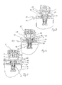
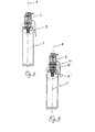
- a compressed gas cartridge 1 is mounted on solenoid valve 2 for compressed gas intake of a drive unit nail-like fasteners, via a connector sealing 3.
- the inlet solenoid valve 2 has a male inlet nozzle 4 extending axially - along the axis 8 - projecting from the bottom 5 of a bowl 6, formed by an annular skirt 7 for receiving an ejection foot 14 of the cartridge 1.
- the end 9 of the inlet nozzle 4 of the solenoid valve is set back relative to the annular edge 10 of the skirt 7.
- the compressed gas cartridge 1 comprises a cylindrical envelope 11 ending with a thick annular bead 12 forming a bowl 13 in the center from which the ejection foot 14 protrudes.
- the foot 14 does not protrude outside the plane of the annular edge 15 of the bead 12. In the example considered, it is flush with it.
- An ejection valve 16 is mounted in the ejection foot 14, sliding in a sleeve-shaped seal 20 against the action of a return spring 17.
- the valve 16 has, projecting from the seal 20, but not outside the bowl 13, an external part 18 extended by an internal part 19 having an annular sealing rim 21.
- the return spring 17 is housed inside the seal sleeve 20, around the internal part of valve 19, in abutment against the annular sealing rim 21 of the part of valve 19, of diameter substantially equal to that of the central bore 22 of the sleeve 20 but very slightly lower, for the exhaust compressed gas between the wall of the bore 22 of the sleeve 20 and this flange 21.
- the flange 21 of the valve 16 is in abutment against a bead sealing ring 23 housed in an annular shoulder of a portion enlarged 24 of the sealing sleeve 20 of the seal 3.
- the seal 3 therefore comprises a sleeve 20 and a cord 23 housed in the foot 14 of which an annular edge 25 covers the enlarged portion 24 of the sleeve and the sealing bead 23.
- the edge 25 of the foot 14 here is flush with the plane of the edge 15 of the bead 12.
- the sealing sleeve 20 is thus slightly set back from the edge plane 15.
- the valve part external 18 has, facing outward, a surface 26 of support and displacement of the valve which, in all circumstances, does not protrude out of the edge plane 15. Here, it is flush with it.
- its external part 18, by its portion adjacent to the surface support 26, protrudes from the sealing bead 23.
- the diameter of the outer valve portion 18 is substantially the same, very slightly smaller, than the diameter of the passage opening 27 of the sealing bead 23 and the same as the outside diameter of the intake nozzle 4.
- the side wall 28 of the external valve part 18 and the outer side wall 29 of the inlet nozzle 4 are successively in contact with the wall of the passage orifice 27 of the sealing bead 23. They constitute cylindrical surfaces sealing, axis 8.
- the end 9 of the endpiece 4 bears against the face 26 of the external valve part 18, arranged perpendicular to axis 8.
- the external valve part 18, in operation is pushed back in the ejection position by the intake nozzle 4 against the action of the spring return 17, to clear the edge of the annular valve 21 of the cord seal 23 and let the gas escape from the cartridge 1 in the solenoid valve 2 of the fixing device.
- the surface support and displacement 26 of the valve 18, 19 is set back relative to the surface 30 facing outwards from the joint bead 23, and even by with respect to its surface 31 facing inwards.
- the seal 3 In the ejection position, the seal 3, with its sleeve 20 and its bead 23 extends on either side of the joint plane of the valve 18, 19 and of the male inlet nozzle 4, which is the plane of the bearing surface 26 of the outer valve part 18.
- an intermediate seal 40 is used mounted in a adapter cap 50.
- the intermediate seal 40 is a sleeve, with a first portion male end 41, mounted in abutment against the bearing surface 26 of the valve 16 to actuate it and move aside its sealing edge 21 of the cord sealing 23, and a second female end portion 42, intended for receive the male inlet nozzle 4 of the solenoid valve 2.
- the diameter outside of the actuating end 41 corresponds to that of the end piece male inlet 4.
- the bore 43 for the passage of compressed gas, extending in the intermediate seal 40, is stepped and its section, in the portion end 42, is significantly larger than at the other end 41 for be of a diameter equal to the outside diameter of the intake nozzle 4. In consequently, the outside diameter of the end portion 42 is also enlarged relative to that of the end portion 41.
- the wall of the enlarged bore 44 in the end portion 42 has a lip sealing ring 45.
- the adapter cap 50 has the shape of a ring with a through bore stepped 51, 52, of section (51) of a diameter substantially equal to the diameter outside of the enlarged female end portion 42 of the intermediate seal 40, in a male end portion 53 intended to be received in the bowl 6 of the solenoid valve 2, and of enlarged section (52) with a diameter substantially equal to the outside diameter of the ejection foot 14 ', in a second female end portion 54 intended to receive this foot ejecting 14 'from the cartridge 1'.
- the bore 51, 52 of the cap 50 extends over a length substantially equal to that of the intermediate seal 40.
- the cap 50 At its end of smaller section 53, the cap 50 has a rim annular 55 for retaining the intermediate seal 40.
- the outer wall 56 of the cover 50 is also stepped, adapted to the bore 51, 52 for receiving the intermediate seal as well as the skirt 7 of the solenoid valve 2 and it ends, at its widened end 54, by an annular edge 57 of outside diameter equal to the inside diameter of the bead 12 of the cartridge 1 'to be received in the bowl 13 of the cartridge 1 '.
Landscapes
- Engineering & Computer Science (AREA)
- General Engineering & Computer Science (AREA)
- Mechanical Engineering (AREA)
- Chemical & Material Sciences (AREA)
- Combustion & Propulsion (AREA)
- Feeding And Controlling Fuel (AREA)
- Valve Housings (AREA)
- Filling Or Discharging Of Gas Storage Vessels (AREA)
- Portable Nailing Machines And Staplers (AREA)
- Lift Valve (AREA)
- Quick-Acting Or Multi-Walled Pipe Joints (AREA)
- Mechanical Coupling Of Light Guides (AREA)
- Steroid Compounds (AREA)
Applications Claiming Priority (2)
| Application Number | Priority Date | Filing Date | Title |
|---|---|---|---|
| FR0116367A FR2833684B1 (fr) | 2001-12-18 | 2001-12-18 | Cartouche de gaz comprime pour appareil de fixation et coiffe d'adaptation d'un joint intermediaire |
| FR0116367 | 2001-12-18 |
Publications (2)
| Publication Number | Publication Date |
|---|---|
| EP1321241A1 true EP1321241A1 (de) | 2003-06-25 |
| EP1321241B1 EP1321241B1 (de) | 2007-06-13 |
Family
ID=8870622
Family Applications (1)
| Application Number | Title | Priority Date | Filing Date |
|---|---|---|---|
| EP02292941A Expired - Lifetime EP1321241B1 (de) | 2001-12-18 | 2002-11-28 | Druckgaspatrone für Befestigungsgerät und Adapter für Verbindungsmuffe |
Country Status (14)
| Country | Link |
|---|---|
| US (1) | US6889731B2 (de) |
| EP (1) | EP1321241B1 (de) |
| JP (1) | JP4405723B2 (de) |
| KR (1) | KR100508275B1 (de) |
| CN (1) | CN1272568C (de) |
| AT (1) | ATE364482T1 (de) |
| AU (1) | AU2002306203B2 (de) |
| CA (1) | CA2414345C (de) |
| DE (1) | DE60220632T2 (de) |
| DK (1) | DK1321241T3 (de) |
| ES (1) | ES2288542T3 (de) |
| FR (1) | FR2833684B1 (de) |
| MX (1) | MXPA02012555A (de) |
| NZ (1) | NZ522921A (de) |
Cited By (2)
| Publication number | Priority date | Publication date | Assignee | Title |
|---|---|---|---|---|
| WO2008076389A1 (en) * | 2006-12-14 | 2008-06-26 | The Gates Corporation | Two stage fluid connector for a pressurized fluid reservoirs |
| DE202013001376U1 (de) | 2013-02-14 | 2013-04-09 | Olaf Kersten | Kartuschenadaptersystem mit Entnahmevorrichtung für gasbetriebene Setzgeräte |
Families Citing this family (20)
| Publication number | Priority date | Publication date | Assignee | Title |
|---|---|---|---|---|
| PT1530002E (pt) * | 2003-11-04 | 2006-09-29 | Cavagna Group Spa | Valvula para recipientes de fluidos pressurizados com dispositivo de bloqueio de sujidade |
| US7478740B2 (en) * | 2006-06-30 | 2009-01-20 | Illinois Tool Works Inc. | Enhanced fuel passageway and adapter for combustion tool fuel cell |
| FR2870921B1 (fr) * | 2004-05-25 | 2007-07-06 | Prospection Et D Inv S Techniq | Adaptateur de raccordement d'une cartouche de gaz et d'un dispositif d'admission de gaz d'un appareil de fixation a gaz, la cartouche, l'electrovanne et l'appareil avec l'adaptateur |
| DE102005006971B3 (de) * | 2005-02-16 | 2006-08-10 | Rothenberger Ag | Adapter für die Verbindung eines Gasverbrauchers mit einer Druckgasflasche |
| FR2884894B1 (fr) * | 2005-04-22 | 2007-06-29 | Prospection Et D Inv S Techniq | Cartouche de gaz de combustion pour appareil de fixation a gaz |
| FR2884892B1 (fr) * | 2005-04-26 | 2010-05-21 | Prospection & Inventions | Ensemble d'un organe de transmission d'energie d'un appareil a actionnement manuel et d'une source d'energie a moyens de blocage en rotation et d'indexage angulaire de la source |
| FR2884896B1 (fr) * | 2005-04-26 | 2007-06-29 | Prospection Et D Inv S Techniq | Raccord d'etancheite et ensemble d'un organe de transmission, d'une cartouche de gaz et d'un adaptateur comprenant le raccord |
| EP2099587B1 (de) * | 2006-11-09 | 2016-02-10 | Stanely Fastening Systems, L.P. | Kabelloses werkzeug zum eintreiben von befestigungselementen |
| KR100861248B1 (ko) * | 2007-04-11 | 2008-10-02 | 주식회사 뉴로스 | 터보블로워용 방풍밸브 |
| US8236046B2 (en) * | 2008-06-10 | 2012-08-07 | Boston Scientific Scimed, Inc. | Bioerodible endoprosthesis |
| FR2941762A1 (fr) * | 2009-02-03 | 2010-08-06 | Taema | Dispositif d'obturation selective d'un passage de fluide, et robinet comportant un tel dispositif |
| US9802303B2 (en) | 2010-04-13 | 2017-10-31 | Illinois Tool Works Inc. | Interface for fuel delivery system for combustion fastener driver |
| US9739367B2 (en) * | 2011-07-14 | 2017-08-22 | Oetiker Ny, Inc. | Transmission anti-leak valve |
| EP3102869B1 (de) * | 2014-02-04 | 2020-01-01 | Strauss Water Ltd | Druckgasbehälter und kupplungsmittel für anwendungen |
| GB2532944A (en) * | 2014-12-01 | 2016-06-08 | Eco-Burner Products Ltd | Improvements in fuel transfer adapters |
| WO2016135715A1 (en) * | 2015-02-25 | 2016-09-01 | Strauss Water Ltd. | Pressurized gas container |
| CN106763760B (zh) * | 2016-11-29 | 2018-07-13 | 宁波照华环保科技有限公司 | 用于净水设备上的防爆压力桶 |
| US10781957B2 (en) * | 2017-01-24 | 2020-09-22 | Staubli Faverges | Fluid coupling element and fluid-coupling comprising such an element |
| US10618152B2 (en) | 2017-08-09 | 2020-04-14 | Black & Decker Inc. | All-direction valve and handheld power tool having same |
| CN109704257A (zh) * | 2018-12-13 | 2019-05-03 | 李保强 | 一种压力桶灌装阀及其工作方法 |
Citations (4)
| Publication number | Priority date | Publication date | Assignee | Title |
|---|---|---|---|---|
| US4971224A (en) * | 1987-07-07 | 1990-11-20 | Application Des Gaz | Valve and container with a valve |
| EP0471503A2 (de) * | 1990-08-14 | 1992-02-19 | Illinois Tool Works Inc. | Ausgabegerät für ein Fluidum |
| EP0922902A1 (de) * | 1997-11-28 | 1999-06-16 | Societe De Prospection Et D'inventions Techniques Spit | Kupplungsstück zwischen einem Druckgassetzgerät und einer Druckgaspatrone |
| US6138714A (en) * | 1999-04-23 | 2000-10-31 | Kim; Dong-Sook | Adapter for a dome-shaped high pressure butane gas container |
Family Cites Families (6)
| Publication number | Priority date | Publication date | Assignee | Title |
|---|---|---|---|---|
| FR1500117A (fr) | 1966-07-18 | 1967-11-03 | Utilisation Ration Gaz | Ensemble d'obturation de sécurité, notamment pour valves de bouteilles de gaz sous pression |
| US4949745A (en) * | 1988-12-27 | 1990-08-21 | Air-Lock, Incorporated | Clean air connector |
| DE4319910C2 (de) * | 1992-06-17 | 2000-04-27 | Isi Metallwarenfabrik Ges M B | Wiederbefüllbare Druckgaskapsel |
| US6467515B1 (en) * | 2001-11-29 | 2002-10-22 | Hwai-Tay Lin | Gas container |
| US8070918B2 (en) * | 2004-09-15 | 2011-12-06 | Sekisui Nano Coat Technology Co., Ltd. | Metal-coated textile |
| KR102112122B1 (ko) * | 2020-01-16 | 2020-05-18 | 김이수 | 멀티형분기관스프레이노즐과 조립식온수관의 온수 분사장치 및 이를 이용한 하수관 보수방법 |
-
2001
- 2001-12-18 FR FR0116367A patent/FR2833684B1/fr not_active Expired - Fee Related
-
2002
- 2002-11-27 AU AU2002306203A patent/AU2002306203B2/en not_active Ceased
- 2002-11-28 DE DE60220632T patent/DE60220632T2/de not_active Expired - Lifetime
- 2002-11-28 AT AT02292941T patent/ATE364482T1/de not_active IP Right Cessation
- 2002-11-28 ES ES02292941T patent/ES2288542T3/es not_active Expired - Lifetime
- 2002-11-28 EP EP02292941A patent/EP1321241B1/de not_active Expired - Lifetime
- 2002-11-28 DK DK02292941T patent/DK1321241T3/da active
- 2002-12-04 NZ NZ522921A patent/NZ522921A/en not_active IP Right Cessation
- 2002-12-06 KR KR10-2002-0077258A patent/KR100508275B1/ko not_active Expired - Fee Related
- 2002-12-12 US US10/317,061 patent/US6889731B2/en not_active Expired - Fee Related
- 2002-12-16 CA CA002414345A patent/CA2414345C/en not_active Expired - Fee Related
- 2002-12-17 CN CNB021571279A patent/CN1272568C/zh not_active Expired - Fee Related
- 2002-12-17 MX MXPA02012555A patent/MXPA02012555A/es active IP Right Grant
- 2002-12-18 JP JP2002366437A patent/JP4405723B2/ja not_active Expired - Fee Related
Patent Citations (4)
| Publication number | Priority date | Publication date | Assignee | Title |
|---|---|---|---|---|
| US4971224A (en) * | 1987-07-07 | 1990-11-20 | Application Des Gaz | Valve and container with a valve |
| EP0471503A2 (de) * | 1990-08-14 | 1992-02-19 | Illinois Tool Works Inc. | Ausgabegerät für ein Fluidum |
| EP0922902A1 (de) * | 1997-11-28 | 1999-06-16 | Societe De Prospection Et D'inventions Techniques Spit | Kupplungsstück zwischen einem Druckgassetzgerät und einer Druckgaspatrone |
| US6138714A (en) * | 1999-04-23 | 2000-10-31 | Kim; Dong-Sook | Adapter for a dome-shaped high pressure butane gas container |
Cited By (3)
| Publication number | Priority date | Publication date | Assignee | Title |
|---|---|---|---|---|
| WO2008076389A1 (en) * | 2006-12-14 | 2008-06-26 | The Gates Corporation | Two stage fluid connector for a pressurized fluid reservoirs |
| US8033523B2 (en) | 2006-12-14 | 2011-10-11 | The Gates Corporation | Systems and methods for two stage fluid path attachment to pressurized fluid reservoirs |
| DE202013001376U1 (de) | 2013-02-14 | 2013-04-09 | Olaf Kersten | Kartuschenadaptersystem mit Entnahmevorrichtung für gasbetriebene Setzgeräte |
Also Published As
| Publication number | Publication date |
|---|---|
| KR100508275B1 (ko) | 2005-08-17 |
| JP4405723B2 (ja) | 2010-01-27 |
| DE60220632D1 (de) | 2007-07-26 |
| AU2002306203B2 (en) | 2005-10-20 |
| CN1428534A (zh) | 2003-07-09 |
| EP1321241B1 (de) | 2007-06-13 |
| US6889731B2 (en) | 2005-05-10 |
| MXPA02012555A (es) | 2003-06-25 |
| NZ522921A (en) | 2003-05-30 |
| JP2003214599A (ja) | 2003-07-30 |
| KR20030051243A (ko) | 2003-06-25 |
| FR2833684B1 (fr) | 2004-05-28 |
| DE60220632T2 (de) | 2008-02-14 |
| ES2288542T3 (es) | 2008-01-16 |
| CA2414345A1 (en) | 2003-06-18 |
| US20030111136A1 (en) | 2003-06-19 |
| ATE364482T1 (de) | 2007-07-15 |
| CN1272568C (zh) | 2006-08-30 |
| CA2414345C (en) | 2007-07-03 |
| FR2833684A1 (fr) | 2003-06-20 |
| DK1321241T3 (da) | 2007-10-15 |
Similar Documents
| Publication | Publication Date | Title |
|---|---|---|
| EP1321241B1 (de) | Druckgaspatrone für Befestigungsgerät und Adapter für Verbindungsmuffe | |
| EP0649683B1 (de) | Abgabevorrichtung mit einer volumenveränderlichen membranartigen Druckkammer | |
| EP0547925B1 (de) | Vorrichtung zum Abgeben eines Produktes, insbesondere eines aufschäumenden Produktes | |
| EP0777049B1 (de) | Vorrichtung zur Verbindung mit einer Pumpe | |
| EP0911565B1 (de) | Schnellverbindung zur Verbindung von starren Rohren in einem Anschlussstück | |
| EP1321242B1 (de) | Verbindungselement zwischen Druckgaspatrone und Befestigungsgerät | |
| EP0486355A1 (de) | Abgabevorrichtung für ein flüssiges bis pastöses Erzeugnis und Halterung für eine solche Abgabevorrichtung | |
| FR2873185A1 (fr) | Cartouche d'implantation pour un raccord de tuyau destine a prendre place dans un logement | |
| EP1171367B1 (de) | Befestigungselement für flüssigkeitsabgabevorrichtungen und abgabevorrichtung die ein solches element enthält | |
| EP1463674B1 (de) | Fluidproduktabgabeventil und dieses umfassende fluidproduktabgabevorrichtung | |
| EP1009540A1 (de) | Abgabevorrichtung mit einem einzusteckenden konischen befestigungsring | |
| EP0874761A1 (de) | Ausgiesser für flüssige oder pastöse produkte | |
| EP1156883B1 (de) | Vorrichtung zur montage einer pumpe auf einen mit einem befestigungskragen versehenen flaschenhals | |
| EP0740101A1 (de) | Schnellkupplung mit einem selbständigen, belasteten Ventil | |
| EP0499754B1 (de) | Verschluss zum dichten Befestigen eines elektrischen Kabels in einer Öffnung und Kabelschutzmuffe mit solchen Verschlüssen | |
| EP0455552B1 (de) | Betätigungsvorrichtung für Ausgabeventil | |
| EP1467842B1 (de) | Druckgaspatrone für befestigungsvorrichtung mit integriertem dichtungsanschluss | |
| EP1352716A1 (de) | Einstückiges Kupplungsstück zwischen einem Druckgassetzgerät und einer Druckgaspatrone | |
| FR2653381A1 (fr) | Instrument de peinture/ecriture. | |
| EP0394139B1 (de) | Zwischenanschlussstück für den Atemgerätendstutzen | |
| FR2692559A1 (fr) | Dispositif de sécurité pour récipient de conditionnement muni d'un organe de distribution comportant une tige de manÓoeuvre. | |
| FR2810302A1 (fr) | Dispositif de reprise d'air dynamique pour distributeur de produit liquide | |
| FR2646654A3 (fr) | Mecanisme de pompage destine a distribuer de la lotion a partir d'une bouteille/conteneur | |
| FR2762807A1 (fr) | Embout de fermeture pour tubulure de remplissage d'un reservoir de carburant d'un vehicule automobile | |
| FR2804490A1 (fr) | Raccord rapide pour le gonflage d'un pneumatique, et pompe de bicyclette comportant un tel raccord |
Legal Events
| Date | Code | Title | Description |
|---|---|---|---|
| PUAI | Public reference made under article 153(3) epc to a published international application that has entered the european phase |
Free format text: ORIGINAL CODE: 0009012 |
|
| AK | Designated contracting states |
Designated state(s): AT BE BG CH CY CZ DE DK EE ES FI FR GB GR IE IT LI LU MC NL PT SE SK TR |
|
| AX | Request for extension of the european patent |
Extension state: AL LT LV MK RO SI |
|
| 17P | Request for examination filed |
Effective date: 20031229 |
|
| AKX | Designation fees paid |
Designated state(s): AT BE BG CH CY CZ DE DK EE ES FI FR GB GR IE IT LI LU MC NL PT SE SK TR |
|
| 17Q | First examination report despatched |
Effective date: 20040308 |
|
| GRAP | Despatch of communication of intention to grant a patent |
Free format text: ORIGINAL CODE: EPIDOSNIGR1 |
|
| GRAS | Grant fee paid |
Free format text: ORIGINAL CODE: EPIDOSNIGR3 |
|
| GRAA | (expected) grant |
Free format text: ORIGINAL CODE: 0009210 |
|
| AK | Designated contracting states |
Kind code of ref document: B1 Designated state(s): AT BE BG CH CY CZ DE DK EE ES FI FR GB GR IE IT LI LU MC NL PT SE SK TR |
|
| REG | Reference to a national code |
Ref country code: GB Ref legal event code: FG4D Free format text: NOT ENGLISH |
|
| REG | Reference to a national code |
Ref country code: CH Ref legal event code: EP |
|
| REG | Reference to a national code |
Ref country code: IE Ref legal event code: FG4D Free format text: LANGUAGE OF EP DOCUMENT: FRENCH |
|
| REF | Corresponds to: |
Ref document number: 60220632 Country of ref document: DE Date of ref document: 20070726 Kind code of ref document: P |
|
| REG | Reference to a national code |
Ref country code: SE Ref legal event code: TRGR |
|
| GBT | Gb: translation of ep patent filed (gb section 77(6)(a)/1977) |
Effective date: 20070912 |
|
| REG | Reference to a national code |
Ref country code: DK Ref legal event code: T3 |
|
| REG | Reference to a national code |
Ref country code: GR Ref legal event code: EP Ref document number: 20070402791 Country of ref document: GR |
|
| PG25 | Lapsed in a contracting state [announced via postgrant information from national office to epo] |
Ref country code: AT Free format text: LAPSE BECAUSE OF FAILURE TO SUBMIT A TRANSLATION OF THE DESCRIPTION OR TO PAY THE FEE WITHIN THE PRESCRIBED TIME-LIMIT Effective date: 20070613 |
|
| REG | Reference to a national code |
Ref country code: ES Ref legal event code: FG2A Ref document number: 2288542 Country of ref document: ES Kind code of ref document: T3 |
|
| PG25 | Lapsed in a contracting state [announced via postgrant information from national office to epo] |
Ref country code: CZ Free format text: LAPSE BECAUSE OF FAILURE TO SUBMIT A TRANSLATION OF THE DESCRIPTION OR TO PAY THE FEE WITHIN THE PRESCRIBED TIME-LIMIT Effective date: 20070613 Ref country code: BG Free format text: LAPSE BECAUSE OF FAILURE TO SUBMIT A TRANSLATION OF THE DESCRIPTION OR TO PAY THE FEE WITHIN THE PRESCRIBED TIME-LIMIT Effective date: 20070913 Ref country code: PT Free format text: LAPSE BECAUSE OF FAILURE TO SUBMIT A TRANSLATION OF THE DESCRIPTION OR TO PAY THE FEE WITHIN THE PRESCRIBED TIME-LIMIT Effective date: 20071113 |
|
| PG25 | Lapsed in a contracting state [announced via postgrant information from national office to epo] |
Ref country code: SK Free format text: LAPSE BECAUSE OF FAILURE TO SUBMIT A TRANSLATION OF THE DESCRIPTION OR TO PAY THE FEE WITHIN THE PRESCRIBED TIME-LIMIT Effective date: 20070613 |
|
| PLBE | No opposition filed within time limit |
Free format text: ORIGINAL CODE: 0009261 |
|
| STAA | Information on the status of an ep patent application or granted ep patent |
Free format text: STATUS: NO OPPOSITION FILED WITHIN TIME LIMIT |
|
| 26N | No opposition filed |
Effective date: 20080314 |
|
| PG25 | Lapsed in a contracting state [announced via postgrant information from national office to epo] |
Ref country code: MC Free format text: LAPSE BECAUSE OF NON-PAYMENT OF DUE FEES Effective date: 20071130 |
|
| PG25 | Lapsed in a contracting state [announced via postgrant information from national office to epo] |
Ref country code: LI Free format text: LAPSE BECAUSE OF NON-PAYMENT OF DUE FEES Effective date: 20071130 Ref country code: CH Free format text: LAPSE BECAUSE OF NON-PAYMENT OF DUE FEES Effective date: 20071130 |
|
| REG | Reference to a national code |
Ref country code: CH Ref legal event code: PL |
|
| PG25 | Lapsed in a contracting state [announced via postgrant information from national office to epo] |
Ref country code: EE Free format text: LAPSE BECAUSE OF FAILURE TO SUBMIT A TRANSLATION OF THE DESCRIPTION OR TO PAY THE FEE WITHIN THE PRESCRIBED TIME-LIMIT Effective date: 20070613 |
|
| PG25 | Lapsed in a contracting state [announced via postgrant information from national office to epo] |
Ref country code: FI Free format text: LAPSE BECAUSE OF FAILURE TO SUBMIT A TRANSLATION OF THE DESCRIPTION OR TO PAY THE FEE WITHIN THE PRESCRIBED TIME-LIMIT Effective date: 20070613 |
|
| PGFP | Annual fee paid to national office [announced via postgrant information from national office to epo] |
Ref country code: GR Payment date: 20081127 Year of fee payment: 7 |
|
| PG25 | Lapsed in a contracting state [announced via postgrant information from national office to epo] |
Ref country code: CY Free format text: LAPSE BECAUSE OF FAILURE TO SUBMIT A TRANSLATION OF THE DESCRIPTION OR TO PAY THE FEE WITHIN THE PRESCRIBED TIME-LIMIT Effective date: 20070613 |
|
| PG25 | Lapsed in a contracting state [announced via postgrant information from national office to epo] |
Ref country code: LU Free format text: LAPSE BECAUSE OF NON-PAYMENT OF DUE FEES Effective date: 20071128 |
|
| PG25 | Lapsed in a contracting state [announced via postgrant information from national office to epo] |
Ref country code: TR Free format text: LAPSE BECAUSE OF FAILURE TO SUBMIT A TRANSLATION OF THE DESCRIPTION OR TO PAY THE FEE WITHIN THE PRESCRIBED TIME-LIMIT Effective date: 20070613 |
|
| PGFP | Annual fee paid to national office [announced via postgrant information from national office to epo] |
Ref country code: IE Payment date: 20091124 Year of fee payment: 8 Ref country code: SE Payment date: 20091127 Year of fee payment: 8 |
|
| PGFP | Annual fee paid to national office [announced via postgrant information from national office to epo] |
Ref country code: IT Payment date: 20091126 Year of fee payment: 8 |
|
| PG25 | Lapsed in a contracting state [announced via postgrant information from national office to epo] |
Ref country code: GR Free format text: LAPSE BECAUSE OF NON-PAYMENT OF DUE FEES Effective date: 20100602 |
|
| REG | Reference to a national code |
Ref country code: SE Ref legal event code: EUG |
|
| PG25 | Lapsed in a contracting state [announced via postgrant information from national office to epo] |
Ref country code: SE Free format text: LAPSE BECAUSE OF NON-PAYMENT OF DUE FEES Effective date: 20101129 |
|
| PG25 | Lapsed in a contracting state [announced via postgrant information from national office to epo] |
Ref country code: IE Free format text: LAPSE BECAUSE OF NON-PAYMENT OF DUE FEES Effective date: 20101129 |
|
| PG25 | Lapsed in a contracting state [announced via postgrant information from national office to epo] |
Ref country code: IT Free format text: LAPSE BECAUSE OF NON-PAYMENT OF DUE FEES Effective date: 20101128 |
|
| PGFP | Annual fee paid to national office [announced via postgrant information from national office to epo] |
Ref country code: DK Payment date: 20121126 Year of fee payment: 11 |
|
| PGFP | Annual fee paid to national office [announced via postgrant information from national office to epo] |
Ref country code: GB Payment date: 20121126 Year of fee payment: 11 Ref country code: ES Payment date: 20121126 Year of fee payment: 11 Ref country code: BE Payment date: 20121129 Year of fee payment: 11 |
|
| PGFP | Annual fee paid to national office [announced via postgrant information from national office to epo] |
Ref country code: FR Payment date: 20131118 Year of fee payment: 12 Ref country code: DE Payment date: 20131127 Year of fee payment: 12 |
|
| PGFP | Annual fee paid to national office [announced via postgrant information from national office to epo] |
Ref country code: NL Payment date: 20131126 Year of fee payment: 12 |
|
| BERE | Be: lapsed |
Owner name: SOC. DE PROSPECTION ET D'INVENTIONS TECHNIQUES SP Effective date: 20131130 |
|
| REG | Reference to a national code |
Ref country code: DK Ref legal event code: EBP Effective date: 20131130 |
|
| GBPC | Gb: european patent ceased through non-payment of renewal fee |
Effective date: 20131128 |
|
| PG25 | Lapsed in a contracting state [announced via postgrant information from national office to epo] |
Ref country code: BE Free format text: LAPSE BECAUSE OF NON-PAYMENT OF DUE FEES Effective date: 20131130 |
|
| PG25 | Lapsed in a contracting state [announced via postgrant information from national office to epo] |
Ref country code: DK Free format text: LAPSE BECAUSE OF NON-PAYMENT OF DUE FEES Effective date: 20131130 |
|
| PG25 | Lapsed in a contracting state [announced via postgrant information from national office to epo] |
Ref country code: GB Free format text: LAPSE BECAUSE OF NON-PAYMENT OF DUE FEES Effective date: 20131128 |
|
| REG | Reference to a national code |
Ref country code: ES Ref legal event code: FD2A Effective date: 20150430 |
|
| REG | Reference to a national code |
Ref country code: DE Ref legal event code: R119 Ref document number: 60220632 Country of ref document: DE |
|
| REG | Reference to a national code |
Ref country code: NL Ref legal event code: V1 Effective date: 20150601 |
|
| PG25 | Lapsed in a contracting state [announced via postgrant information from national office to epo] |
Ref country code: ES Free format text: LAPSE BECAUSE OF NON-PAYMENT OF DUE FEES Effective date: 20131129 |
|
| REG | Reference to a national code |
Ref country code: FR Ref legal event code: ST Effective date: 20150731 |
|
| PG25 | Lapsed in a contracting state [announced via postgrant information from national office to epo] |
Ref country code: NL Free format text: LAPSE BECAUSE OF NON-PAYMENT OF DUE FEES Effective date: 20150601 |
|
| PG25 | Lapsed in a contracting state [announced via postgrant information from national office to epo] |
Ref country code: DE Free format text: LAPSE BECAUSE OF NON-PAYMENT OF DUE FEES Effective date: 20150602 |
|
| PG25 | Lapsed in a contracting state [announced via postgrant information from national office to epo] |
Ref country code: FR Free format text: LAPSE BECAUSE OF NON-PAYMENT OF DUE FEES Effective date: 20141201 |