EP0146249A2 - Glasfaserprodukte - Google Patents
Glasfaserprodukte Download PDFInfo
- Publication number
- EP0146249A2 EP0146249A2 EP84307610A EP84307610A EP0146249A2 EP 0146249 A2 EP0146249 A2 EP 0146249A2 EP 84307610 A EP84307610 A EP 84307610A EP 84307610 A EP84307610 A EP 84307610A EP 0146249 A2 EP0146249 A2 EP 0146249A2
- Authority
- EP
- European Patent Office
- Prior art keywords
- casing
- roving
- filling
- airstream
- prior
- Prior art date
- Legal status (The legal status is an assumption and is not a legal conclusion. Google has not performed a legal analysis and makes no representation as to the accuracy of the status listed.)
- Granted
Links
Images


Classifications
-
- F—MECHANICAL ENGINEERING; LIGHTING; HEATING; WEAPONS; BLASTING
- F01—MACHINES OR ENGINES IN GENERAL; ENGINE PLANTS IN GENERAL; STEAM ENGINES
- F01N—GAS-FLOW SILENCERS OR EXHAUST APPARATUS FOR MACHINES OR ENGINES IN GENERAL; GAS-FLOW SILENCERS OR EXHAUST APPARATUS FOR INTERNAL-COMBUSTION ENGINES
- F01N13/00—Exhaust or silencing apparatus characterised by constructional features
- F01N13/18—Construction facilitating manufacture, assembly, or disassembly
-
- F—MECHANICAL ENGINEERING; LIGHTING; HEATING; WEAPONS; BLASTING
- F01—MACHINES OR ENGINES IN GENERAL; ENGINE PLANTS IN GENERAL; STEAM ENGINES
- F01N—GAS-FLOW SILENCERS OR EXHAUST APPARATUS FOR MACHINES OR ENGINES IN GENERAL; GAS-FLOW SILENCERS OR EXHAUST APPARATUS FOR INTERNAL-COMBUSTION ENGINES
- F01N1/00—Silencing apparatus characterised by method of silencing
- F01N1/24—Silencing apparatus characterised by method of silencing by using sound-absorbing materials
-
- F—MECHANICAL ENGINEERING; LIGHTING; HEATING; WEAPONS; BLASTING
- F01—MACHINES OR ENGINES IN GENERAL; ENGINE PLANTS IN GENERAL; STEAM ENGINES
- F01N—GAS-FLOW SILENCERS OR EXHAUST APPARATUS FOR MACHINES OR ENGINES IN GENERAL; GAS-FLOW SILENCERS OR EXHAUST APPARATUS FOR INTERNAL-COMBUSTION ENGINES
- F01N2310/00—Selection of sound absorbing or insulating material
- F01N2310/02—Mineral wool, e.g. glass wool, rock wool, asbestos or the like
-
- F—MECHANICAL ENGINEERING; LIGHTING; HEATING; WEAPONS; BLASTING
- F01—MACHINES OR ENGINES IN GENERAL; ENGINE PLANTS IN GENERAL; STEAM ENGINES
- F01N—GAS-FLOW SILENCERS OR EXHAUST APPARATUS FOR MACHINES OR ENGINES IN GENERAL; GAS-FLOW SILENCERS OR EXHAUST APPARATUS FOR INTERNAL-COMBUSTION ENGINES
- F01N2450/00—Methods or apparatus for fitting, inserting or repairing different elements
- F01N2450/06—Inserting sound absorbing material into a chamber
-
- F—MECHANICAL ENGINEERING; LIGHTING; HEATING; WEAPONS; BLASTING
- F01—MACHINES OR ENGINES IN GENERAL; ENGINE PLANTS IN GENERAL; STEAM ENGINES
- F01N—GAS-FLOW SILENCERS OR EXHAUST APPARATUS FOR MACHINES OR ENGINES IN GENERAL; GAS-FLOW SILENCERS OR EXHAUST APPARATUS FOR INTERNAL-COMBUSTION ENGINES
- F01N2470/00—Structure or shape of exhaust gas passages, pipes or tubes
- F01N2470/02—Tubes being perforated
-
- Y—GENERAL TAGGING OF NEW TECHNOLOGICAL DEVELOPMENTS; GENERAL TAGGING OF CROSS-SECTIONAL TECHNOLOGIES SPANNING OVER SEVERAL SECTIONS OF THE IPC; TECHNICAL SUBJECTS COVERED BY FORMER USPC CROSS-REFERENCE ART COLLECTIONS [XRACs] AND DIGESTS
- Y10—TECHNICAL SUBJECTS COVERED BY FORMER USPC
- Y10T—TECHNICAL SUBJECTS COVERED BY FORMER US CLASSIFICATION
- Y10T29/00—Metal working
- Y10T29/49—Method of mechanical manufacture
- Y10T29/49398—Muffler, manifold or exhaust pipe making
Definitions
- Glass and/or mineral fibres are widely used for thermal and/or acoustic insulation.
- glass fibres it is common practice to chop continuous filament material into short lengths (staple fibres), thereafter forming a mat from the staple fibres produced, or simply packing the staple fibres into a supporting member.
- staple fibres are packed into automotive silencer casings, into cavity walls, or are incorporated into sandwich panels for use in building construction.
- the process just described employs a conventional textile bulking or texturing jet as a means of exposing a continuous filament roving to the action of a highly turbulent airstream. It also uses a separate cutter device operable to sever the roving on completion of each silencer filling operation.
- EP-A-0091413 discloses a process for filling a silencer casing, but only from one open end thereof. Such a process is effective for roughly half of the commonly used types of absorptive silencer. There are however other very commonly used types of absorptive silencer where the process just refered to is ineffective and/or inefficient. For example there are "straight-through" silencers, the automated production of which includes the step of fitting both end caps at once. For these, it is normal to use a glass fibre preform made in situ around a length of perforated exhaust gas duct to locate the latter duct inside the casing prior to affixing the end caps. Preform manufacture is an essential, extra step in this particular process.
- silencers which have two separate fibre-filled absorptive regions either. side of a reactive element comprising baffles in an intermediate fibre free volume.
- the absorptive regions may be of different shapes and/or sizes, but once again it is normal to fit both end closures at the same time. It is an object of the present invention to provide an improved process and apparatus for filling a silencer casing with glass fibres.
- a process for filling a silencer casing with glass fibres is characterised by the steps of presenting oppositely directed open ends of the casing substantially simultaneously to glass fibre feeding stations and filling the casing from both ends thereof. Subsequently closures are affixed to said ends, preferably simultaneously.
- the process includes the steps of feeding continuous filament glass fibre roving to each feeding station and converting the roving to relatively bulky form prior to filling the casing with it.
- the roving may also be cut into staple prior to bulking, but preferably it remains in continuous filament form throughout the process.
- the roving is preferably converted to relatively bulky form by the step of subjecting it to an air treatment in a known bulking jet. More preferably, however, the air treatment is carried out by causing the roving to pass through a bulking jet having novel constructional features, which will be discussed in detail later in this specification.
- the process of the invention is preferably further characterised by the step of temporarily locating one end of a tubular spacer element on each open end of the casing prior to the filling step.
- the filling step is in this particular instance carried out until an overflow or excess of fibres has been deposited in the spacer element and this is then followed by the further step of pushing the overflow from the spacer elements into the casing prior to removing the spacer element and subsequently affixing the closures to the ends of the casing.
- spacer element effectively increases the volume to be filled, so that not only is any overflow completely contained within the spacer element, but by pushing the overflow out of the spacer el-ement into the casing, the latter can be filled to a substantially uniform density.
- Metering the feed of glass fibre by length is relatively easy and accurate, so that the actual quantity (mass) of bulked fibres (stable or continuous filament) can be fully controlled. It remains only to monitor the quality of bulking and the pressure applied to push the overflow into the casing.
- the process of the invention should be further modified by addition of the steps of locating and/or temporarily retaining the tube axially and radially with respect to the casing at least until there is sufficient in-filled material to do so.
- apparatus for filling a silencer casing includes two glass fibre feeding stations and means for presenting oppositely directed open ends of the casing to said stations substantially simultaneously.
- each feeding station comprises at least one bulking jet operable to bulk a continuous filament glass fibre roving prior to deposition in the casing by the jet as bulked continuous filaments.
- Each feeding station may have more than one bulking jet together with individual roving supply means for each such jet, the jets being arranged to reflect the cross-sectional shape and volume of the casing to be filled.
- a bulking jet comprises a roving entry passageway, an airstream entry passageway and means for distributing the airstream evenly around the roving as an essentially annular sheath in the region of contact there-between, together with a common outlet passageway for the airstream and roving, characterised in that the flow restriction due to that area of the annulus defining said sheath immediately prior to said region of contact is significantly less than that due to the common outlet passageway. It will be understood that the latter restriction is referred to the outlet passageway in use, that is in the presence of both air and glass fibre rov-ing.
- the length to diameter ratio of the preferably cylindrical, parallel sided common outlet passageway should be in the range 5 to 10, with a ratio of 8 being especially preferred.
- typical roving throughput speeds of at least 500 metres/minute being required to achieve high speed filling of silencer casings on a production line basis
- the construction of the bulking jet has been found to have very significant effect on the efficiency of the process, to the extent that conventional textile bulking/texturing jets are unsatisfactory by comparison with a jet according to this invention.
- roving clamp operable to hold the roving, for example against the thread guide after breaking in the jet.
- the jet of this invention preferably not only has a parallel sided outlet passage but also the latter terminates abruptly to give sharp, almost explosive expansion of the air/roving mixture emerging from it. Because of the unusually high forces developed on the roving in the outlet passageway itself, it is necessary to minimize air leakage back along the roving entry passageway. However, it is also highly desirable that the latter should accept not just the roving but also a splice therein, since it is advantageous to be able to join roving packages end-to-end to give essentially continuous running. The diameter of such a splice will usually be at least twice the diameter of the roving itself, so the roving entry passageway must be considerably larger than the roving alone.
- silencer filling processes using the jets of this invention is the need to minimize the risk of loops or snarls developing in the (or each) roving being fed to the jet. This problem is made very much worse by the fabt that silencer filling is a batchwise process resulting in rapid stop-start operation.
- the roving feed has to be stopped and re-started from (and then to) a high linear speed, typically over 500 metres/minute. It has been found that this can be accomplished by eliminating conventional tension control devices, yarn accumulators and the like. Instead, a godet wheel driven through a clutch/brake unit is used, the clutch/brake serving to give a fully controlled rate of deceleration from and acceleration to the desired speed.
- The'apparatus preferably includes a tubular spacer element associated with each feeding station, together with means for presenting said spacer element to one open end of the casing so as to constitute an extension of the casing intermediate the casing and the feeding station itself.
- the apparatus then preferably includes presser means operable to push any overflow of glass fibres from the spacer element into the casing prior to transfer of the latter to apparatus operable to affix closures to the ends thereof.
- the volume of the spacer element is not critical, but it is preferred that it should be of the order of up to 50% of that of the silencer casing itself.
- the spacer element is of similar cross-sectional shape to the silencer casing to be filled. It is also advantageous that it should have a resilent facing on that region which is in use to be abutted against the leakage casing. This is useful to minimise both are leakage and mechanical alignment problems.
- the actual cross-sectional shape of the spacer element and/or silencer casing is not critical; the invention can cope equally well with the oval, elliptical or circular sections encountered in the automotive industry.
- the apparatus preferably includes means for so doing at least until the tube is sufficiently supported by the in-filled glass fibres.
- Magnets associated with each feeding station are the preferred means of temporarily locating the tube to be supported by or to the feeding station so that the air can escape down the tube and through the filling station without interfering with the filling process.
- the filling stations may be mounted on a common support rail arrangement so that they can be advanced, for example by pneumatic cylinders, towards one another, to meet the oppositely directed open ends of a silencer ca-sing which is presented between them by the action of a form of a conveyor system.
- the headstocks themselves may be caused to traverse with the latter conveyor system during the filling operation and prior to return to their starting point where they engage the next casing to be filled.
- the precise arrangement adopted will reflect the nature of the silencer production line, but the bulking jets and the spacer element/presser means are preferably those disclosed above.
- the invention further includes a silencer production line equipped with the apparatus of this invention, or modified to carry out the process of this invention.
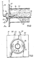
- Figure 7 shows a modified version of Figure 5 in rather more detail and Figure 8 shows it as seen from direction A in Figure 7.
- Figure 9 illustrates the internal construction of a particularly preferred form of bulking jet for use at any of the filling stations shown.
- a cylindrical casing 1 has a centrally-disposed perforated tube 2 extending between and through end closures 3 and 4.
- the volume surrounding the tube is filled with glass fibre 5.
- the tube is otherwise unsupported until the closures are seamed to it and to the casing, except by the filling 5.
- the same casing 1 and closures 3 and 4 are used, but the tube 2 is in two portions 6, 7 respectively, the ends of which overlap inside the casing to abut against internal partitions 9, 8 respecitvely.
- the partitions and casing together define a blind volume 10 between two separate volumes filled with fibre, 11, 12.
- FIG. 1 one open end 16 of a silencer casing of the Figure 1 (straight-through) kind is shown with a lengh of perforated tube 17 lying inside it.
- a filling station Advancing axially towards it is a filling station, parts only of which are shown, in the interests of simplicity.
- the casing is supported by a conveyor (not shown) incorporating a magnet operable to hold the tube 17 relative to the casing until engaged by the filling station.
- the latter comprises a tubular spacer element 13 having resilient marginal portion 14 configured to locate and seal against the open end of the casing 16.
- a central support 15 advances with the spacer element until its shaped end 18 engages the tube 17 and lifts it away from the casing to a desired position relative to the centre line of the casing, as shown in Figure 4.
- the centre 19 of the support 15 is hollow, to enable air to escape from the casing through the perforations in the tube 17. It will be appreciated that exactly the same arrangement applies at the opposite end of the casing, so that filling can take place from both ends at once.
- the length of the tube 17 will normally be greater than that of the casing and if so the length of the support 15 can be suitably changed to accommodate the projection of tube 17 beyond the end of the casing.
- the presser means which are preferably used to pack any overflow of glass fibres into the casing from inside the spacer element 13. After such a packing operation, the tube 17 will not normally require further support; the silencer casing, the tube and in'-filled material can be forwarded for installation of the end closures in the usual way.
- Figures 5 and 6 show a modified apparatus in which a backing plate 31 carries two bulking jets 32, each of which is supplied with continuous filament glass fibre roving 34 and high pressure air (typically at 450 KN/M 2 ) through pipe 33.
- the jets are preferably of the kind discussed below.
- the plate 31 has a resilient face 35 which abuts against the open end of a silencer casing 36.
- the casing contains a perforated exhaust gas duct 37, the free end of which is located by and against a locating stud 38 on the plate 31. This also serves to prevent glass fibres being blown down into the duct, the opposite end A of which is open to allow the free escape of air from the casing during filling.
- the rovings 34 are metered from roving packages (not shown) by means of godet wheels (not shown) operated in the manner discussed earlier.
- the operation of the station just described results in rapid filling of the casing with bulked glass fibres 40, at least until the bulk density approaches about 50 kg/m3, or roughly half of a typical target bulk density in the range 80 to 100 kg/m3.
- the quality of the bulking process then falls off, to the point where free passage of material into the casing becomes severely impaired and eventually stops.
- This gives unstable running conditions for the apparatus/process and results in variable bulk density, together with some overflow of material from the casing on transfer to the next production step, which is the installation of an end cap for the casing.
- Figures 7 and 8 show the apparatus of Figures 5 and 6 further modified in accordance with a preferred feature of invention.
- a spacer element 50 having a resilient, silencer casing - contacting margin 51 is interposed between the casing 36 and the backplate 31.
- a corresponding extension 58 of the original stud 38 is provided to locate and close the perforated duct 37.
- a press plate 52 is included together with rods 53 operable to displace the plate as indicated by dashed lines towards and into the mouth of the casing (54).
- the press plate is configured to slide around the stud 38 and incorporates cut-outs to clear the jet nozzles.
- Figure 9 shows a diagrammatic cross-sectional side view (on an enlarged scale) of a bulking jet in accordance with the invention.
- the jet comprises a body 62 provided with airstream entry passage 65, a needle 61 in which there is a thread guide 64 opening into a roving entry passage 67, together with an outlet section 63 provided with an outlet passageway 9 terminating abruptly in a flat surface 70.
- the needle 61 terminates in an annular space 66 defined inside the body 62.
- the open end of the needle in that space and the opposed entrance to the outlet passageway 69 together define an annular space 68 extending between the space 66 and the inside of the passageway 69.
- the needle Unlike a conventional bulking jet it is not necessary that the needle should be slidably mounted so that the effective area of the space 68 can be changed by relative axial movement of the needle, whilst retaining a constant, acute angle of contact between air and roving. As previously explained, the outlet passageway 69 is the critical factor.
- jets of the kind just described is extremely advantageous for the purposes of this invention, namely the filling of automotive silencer casings with glass fibres.
Landscapes
- Engineering & Computer Science (AREA)
- Chemical & Material Sciences (AREA)
- Combustion & Propulsion (AREA)
- Mechanical Engineering (AREA)
- General Engineering & Computer Science (AREA)
- Exhaust Silencers (AREA)
- Nonwoven Fabrics (AREA)
Applications Claiming Priority (6)
| Application Number | Priority Date | Filing Date | Title |
|---|---|---|---|
| GB8330800 | 1983-11-18 | ||
| GB8330801 | 1983-11-18 | ||
| GB8330799 | 1983-11-18 | ||
| GB838330799A GB8330799D0 (en) | 1983-11-18 | 1983-11-18 | Glass fibre products |
| GB838330800A GB8330800D0 (en) | 1983-11-18 | 1983-11-18 | Glass fibre products |
| GB838330801A GB8330801D0 (en) | 1983-05-17 | 1983-11-18 | Glass fibre products |
Publications (3)
| Publication Number | Publication Date |
|---|---|
| EP0146249A2 true EP0146249A2 (de) | 1985-06-26 |
| EP0146249A3 EP0146249A3 (en) | 1987-03-25 |
| EP0146249B1 EP0146249B1 (de) | 1989-01-18 |
Family
ID=27262220
Family Applications (1)
| Application Number | Title | Priority Date | Filing Date |
|---|---|---|---|
| EP84307610A Expired EP0146249B1 (de) | 1983-11-18 | 1984-11-05 | Glasfaserprodukte |
Country Status (8)
| Country | Link |
|---|---|
| US (1) | US4774985A (de) |
| EP (1) | EP0146249B1 (de) |
| BR (1) | BR8405864A (de) |
| CA (1) | CA1238613A (de) |
| DE (1) | DE3476241D1 (de) |
| ES (1) | ES8604670A1 (de) |
| GB (1) | GB2149851B (de) |
| MX (1) | MX163173B (de) |
Cited By (3)
| Publication number | Priority date | Publication date | Assignee | Title |
|---|---|---|---|---|
| EP0396753A4 (en) * | 1988-07-28 | 1991-03-27 | Yamato Co: Ltd | Silencer for combustion exhaust gas |
| US5114711A (en) * | 1985-12-02 | 1992-05-19 | G. D. Searle & Co. | Covalently linked polypeptide cell modulators such as interferon-lymphotoxin conjugates |
| RU2191319C2 (ru) * | 1996-12-03 | 2002-10-20 | Оуэнс-Корнинг Сведен Аб | Способ формования заготовки из прядевого стекловолокнистого материала (варианты) и устройство для его осуществления |
Families Citing this family (32)
| Publication number | Priority date | Publication date | Assignee | Title |
|---|---|---|---|---|
| JP3207608B2 (ja) * | 1993-04-19 | 2001-09-10 | 三恵技研工業株式会社 | 消音器の製造方法および製造装置 |
| AU5894998A (en) * | 1996-12-02 | 1998-06-29 | Owens Corning | Molded insulation products and their manufacture using continuous-filament wool |
| US5926954A (en) * | 1997-09-10 | 1999-07-27 | Acoust-A-Fiber Research & Development, Inc. | Method of making a silencer |
| DE59813552D1 (de) * | 1997-12-24 | 2006-06-29 | Eberspaecher J Gmbh & Co | Verfahren zur Herstellung eines Absorptions-Schalldämpfers |
| NL1009168C2 (nl) * | 1998-05-14 | 1999-11-16 | Scambia Ind Dev Ag | Werkwijze en inrichting voor het vervaardigen van een geluiddemper. |
| US6053276A (en) * | 1998-06-09 | 2000-04-25 | D'amico, Jr.; John | Muffler packing method with injection of cartrided continuous filament fiberglass |
| US5976453A (en) * | 1998-06-29 | 1999-11-02 | Owens-Corning Sweden Ab | Device and process for expanding strand material |
| US6317959B1 (en) * | 1999-02-16 | 2001-11-20 | Owens Corning Sweden A.B. | Process and apparatus for packing insulation material in a passage between first and second elements |
| US20030116307A1 (en) * | 2000-05-09 | 2003-06-26 | Filippo Amadio | Insulating preform |
| IT1321250B1 (it) * | 2000-05-09 | 2004-01-08 | Filippo Amadio | Mantello isolante |
| US6543576B1 (en) | 2000-07-18 | 2003-04-08 | Owens-Corning Fiberglas Technology, Inc. | Multiple layer fiber filled sound absorber and a method of manufacturing the same |
| DE10048118A1 (de) * | 2000-09-28 | 2002-04-11 | Eberspaecher J Gmbh & Co | Verfahren zur Herstellung eines Absorptions-Schalldämpfers für Kraftfahrzeuge sowie Absorptions-Schalldämpfer |
| EP1332071B1 (de) | 2000-11-07 | 2008-09-10 | Owens Corning | Stossstangen / schalldämpferanordnung |
| US6467571B2 (en) | 2000-12-11 | 2002-10-22 | Nakagawa Sangyo Co., Ltd. | Sound absorbing material, muffler using the sound absorbing material, and method for forming sound absorbing layer thereof |
| DE60003201T2 (de) * | 2000-12-14 | 2003-12-18 | Nakagawa Sangyo Co., Ltd. | Schallschluckendes Material, Schalldämpfer mit diesem schallschluckenden Material, und Verfahren zur Formung einer schallschluckenden Schicht hierfür |
| US6412596B1 (en) | 2001-02-01 | 2002-07-02 | Owens Corning Composites Sprl | Process for filling a muffler and muffler filled with fibrous material |
| US6446750B1 (en) | 2001-03-16 | 2002-09-10 | Owens Corning Fiberglas Technology, Inc. | Process for filling a muffler shell with fibrous material |
| US6581723B2 (en) | 2001-08-31 | 2003-06-24 | Owens Corning Composites Sprl | Muffler shell filling process, muffler filled with fibrous material and vacuum filling device |
| US6607052B2 (en) | 2001-09-12 | 2003-08-19 | Owens Corning Composites Sprl | Muffler shell filling process and muffler filled with fibrous material |
| US7077922B2 (en) | 2003-07-02 | 2006-07-18 | Owens Corning Composites S.P.R.L. | Technique to fill silencers |
| US7165648B2 (en) * | 2004-06-22 | 2007-01-23 | Owens Corning Fiberglas Technology, Inc. | Method for containing an acoustical material within an assembly |
| US7942237B2 (en) * | 2006-04-12 | 2011-05-17 | Ocv Intellectual Capital, Llc | Long fiber thermoplastic composite muffler system with integrated reflective chamber |
| US7934580B2 (en) * | 2006-04-12 | 2011-05-03 | Ocv Intellectual Capital, Llc | Long fiber thermoplastic composite muffler system |
| US7975382B2 (en) * | 2007-10-30 | 2011-07-12 | Ocv Intellectual Capital, Llc | Method for filling a muffler cavity |
| US20100307863A1 (en) * | 2007-12-14 | 2010-12-09 | Ocv Intellectual Capital, Llc | Composite muffler system thermosetable polymers |
| US8590155B2 (en) * | 2009-06-03 | 2013-11-26 | Ocv Intellectual Capital, Llc | Apparatus for and process of filling a muffler with fibrous material utilizing a directional jet |
| US8623263B2 (en) * | 2009-08-05 | 2014-01-07 | Ocv Intellectual Capital, Llc | Process for curing a porous muffler preform |
| US20110031660A1 (en) * | 2009-08-05 | 2011-02-10 | Huff Norman T | Method of forming a muffler preform |
| US8474115B2 (en) * | 2009-08-28 | 2013-07-02 | Ocv Intellectual Capital, Llc | Apparatus and method for making low tangle texturized roving |
| US8336673B2 (en) | 2010-07-07 | 2012-12-25 | Bay Industries Inc. | Muffler, muffler insert, and methods and apparatus for making |
| US9938872B2 (en) | 2015-06-09 | 2018-04-10 | Bay Fabrication, Inc. | Muffler insert, and systems, methods and apparatus for making |
| EP3336326A1 (de) * | 2016-12-19 | 2018-06-20 | OCV Intellectual Capital, LLC | System und verfahren zum füllen von schalldämpfern mit fasermaterial |
Family Cites Families (25)
| Publication number | Priority date | Publication date | Assignee | Title |
|---|---|---|---|---|
| CA698172A (en) * | 1964-11-17 | Black Products Co. | Self venting spout | |
| US1676734A (en) * | 1922-12-16 | 1928-07-10 | Gilmont Products Corp | Apparatus and method for filling collapsible tubes |
| US2501652A (en) * | 1946-03-27 | 1950-03-28 | Hutchens Ind | Method of and apparatus for stuffing oil filter elements |
| GB666591A (en) * | 1949-03-29 | 1952-02-13 | Fibreglass Ltd | Improvements in or relating to fibrous mats or webs |
| US2821346A (en) * | 1953-04-23 | 1958-01-28 | Majac Inc | Injector for impact pulverizer or the like |
| US2777481A (en) * | 1954-09-09 | 1957-01-15 | Atkinson Bulk Transp Company | Railroad car filling device |
| US2982082A (en) * | 1954-10-20 | 1961-05-02 | British Celanese | Production of voluminous yarn |
| US2924868A (en) * | 1956-09-13 | 1960-02-16 | Eastman Kodak Co | Jet device for blowing yarn and process |
| US3062246A (en) * | 1959-02-04 | 1962-11-06 | Koehler Aircraft Products Comp | Fill valve |
| GB893020A (en) * | 1959-06-30 | 1962-04-04 | Du Pont | Improvements in apparatus for production of voluminous yarns and products produced thereby |
| US3317296A (en) * | 1962-12-26 | 1967-05-02 | Pittsburgh Plate Glass Co | Process of making fibrous product |
| GB1046197A (en) * | 1964-06-09 | 1966-10-19 | British Nylon Spinners Ltd | Yarns polymeric material and a process and apparatus for making same |
| US3485593A (en) * | 1967-06-09 | 1969-12-23 | Ethyl Corp | Exhaust treating device |
| CH508543A (de) * | 1968-05-02 | 1971-06-15 | Luwa Ag | Vorrichtung zum Abscheiden von Material aus einem Transportluftstrom |
| US3613830A (en) * | 1969-07-18 | 1971-10-19 | Walker Mfg Co | One-piece tube and shell assembly for silencer |
| GB1279472A (en) * | 1969-10-30 | 1972-06-28 | Harmo Ind Ltd | Improvements in or relating to absorbent devices |
| US3650001A (en) * | 1970-12-24 | 1972-03-21 | Phillips Petroleum Co | Yarn texturing apparatus |
| US3671168A (en) * | 1971-06-09 | 1972-06-20 | Bischoff Chemical Corp | Low heat capacity mold for injection molding |
| US3955643A (en) * | 1974-07-03 | 1976-05-11 | Brunswick Corporation | Free flow sound attenuating device and method of making |
| DE2727446A1 (de) * | 1977-06-18 | 1979-01-04 | Holstein & Kappert Maschf | Verfahren zum abfuellen von fluessigkeiten in behaelter |
| SE408792B (sv) * | 1977-11-09 | 1979-07-09 | Rockwool Ab | Sett och anordning for tillverkning av formstycken av mineralull |
| SE445942B (sv) * | 1982-04-06 | 1986-07-28 | Volvo Ab | Ljuddempare samt sett och anordning for framstellning av denna |
| US4486932A (en) * | 1982-08-06 | 1984-12-11 | Apx Group, Inc. | Process for making a replacement muffler |
| GB2127093B (en) * | 1982-09-10 | 1986-01-29 | Unipart Group Ltd | Packing automobile exhaust silencer casing |
| US4565227A (en) * | 1984-06-15 | 1986-01-21 | Outboard Marine Corporation | Process and apparatus for surrounding foam pattern with sand |
-
1984
- 1984-11-05 DE DE8484307610T patent/DE3476241D1/de not_active Expired
- 1984-11-05 EP EP84307610A patent/EP0146249B1/de not_active Expired
- 1984-11-08 GB GB08428236A patent/GB2149851B/en not_active Expired
- 1984-11-13 CA CA000467582A patent/CA1238613A/en not_active Expired
- 1984-11-16 BR BR8405864A patent/BR8405864A/pt not_active IP Right Cessation
- 1984-11-16 MX MX203417A patent/MX163173B/es unknown
- 1984-11-16 ES ES537713A patent/ES8604670A1/es not_active Expired
-
1987
- 1987-08-28 US US07/090,349 patent/US4774985A/en not_active Expired - Fee Related
Cited By (4)
| Publication number | Priority date | Publication date | Assignee | Title |
|---|---|---|---|---|
| US5114711A (en) * | 1985-12-02 | 1992-05-19 | G. D. Searle & Co. | Covalently linked polypeptide cell modulators such as interferon-lymphotoxin conjugates |
| EP0396753A4 (en) * | 1988-07-28 | 1991-03-27 | Yamato Co: Ltd | Silencer for combustion exhaust gas |
| BE1002925A3 (fr) * | 1988-07-28 | 1991-08-20 | Hideo Yoshikawa | Silencieux pour gaz de combustion. |
| RU2191319C2 (ru) * | 1996-12-03 | 2002-10-20 | Оуэнс-Корнинг Сведен Аб | Способ формования заготовки из прядевого стекловолокнистого материала (варианты) и устройство для его осуществления |
Also Published As
| Publication number | Publication date |
|---|---|
| ES537713A0 (es) | 1986-02-01 |
| EP0146249A3 (en) | 1987-03-25 |
| CA1238613A (en) | 1988-06-28 |
| GB2149851A (en) | 1985-06-19 |
| DE3476241D1 (en) | 1989-02-23 |
| GB2149851B (en) | 1987-05-13 |
| BR8405864A (pt) | 1985-09-17 |
| US4774985A (en) | 1988-10-04 |
| ES8604670A1 (es) | 1986-02-01 |
| EP0146249B1 (de) | 1989-01-18 |
| MX163173B (es) | 1991-09-30 |
| GB8428236D0 (en) | 1984-12-19 |
Similar Documents
| Publication | Publication Date | Title |
|---|---|---|
| EP0146249B1 (de) | Glasfaserprodukte | |
| EP0091413B1 (de) | Behälter durch den ein Gas fliesst, vorzugsweise ein Dämpfer, mit Glasfaserfüllung und Verfahren und Vorrichtung zum Füllen | |
| US2431205A (en) | Apparatus for manufacturing fibrous glass | |
| US3650104A (en) | Spinning of textile yarns | |
| US3447298A (en) | Turbine spinning apparatus | |
| EP1151223B1 (de) | Vorrichtung und verfahren zum packen von isolationsmaterial in einem übergang zwischen einem ersten und einem zweiten element | |
| GB1471967A (en) | Apparatus for feeding fibres to the inner wall of a spinning rotor of an open-end spinning apparatus | |
| US2976580A (en) | Device for preparing a fleece, sliver or yarn, in particular of glass | |
| EP0183543A2 (de) | Vorrichtung zum Schneiden von länglichem Material in kürzere Längen | |
| US2079094A (en) | Apparatus for opening staple fibers | |
| US4083173A (en) | Method and apparatus for the manufacture of core yarn in an open-end spinning device | |
| US4653260A (en) | Process and apparatus for preparing a cut-to-length thread end for the re-piecing of an open-end spinning machine | |
| US2418125A (en) | Method and apparatus for producing crimped staple fibers | |
| US3952959A (en) | Textile yarn processing | |
| US4553383A (en) | Method of and apparatus for spinning yarn from staple fibers in an air vortex | |
| US4628685A (en) | Yarn piecing arrangement for an open-end friction spinning machine | |
| EP0106481A2 (de) | Packung des Abgasschalldämpfers von Kraftfahrzeugen | |
| JPH0449951B2 (de) | ||
| US4625506A (en) | Open-end spinning process and device | |
| US3110150A (en) | Yarn spinning machine | |
| US2581467A (en) | Device for cutting staple fiber | |
| US3154836A (en) | Method and apparatus for handling continuous filamentary material | |
| US4606184A (en) | Arrangement for stopping and starting an open-end friction spinning unit | |
| GB2158001A (en) | A moulding for inserting into an exhaust silencer casing | |
| EP0153100B1 (de) | Verfahren und Einrichtung zur Verpackung des Abgasschalldämpfers |
Legal Events
| Date | Code | Title | Description |
|---|---|---|---|
| PUAI | Public reference made under article 153(3) epc to a published international application that has entered the european phase |
Free format text: ORIGINAL CODE: 0009012 |
|
| AK | Designated contracting states |
Designated state(s): BE DE FR IT NL SE |
|
| PUAL | Search report despatched |
Free format text: ORIGINAL CODE: 0009013 |
|
| AK | Designated contracting states |
Kind code of ref document: A3 Designated state(s): BE DE FR IT NL SE |
|
| 17P | Request for examination filed |
Effective date: 19870907 |
|
| 17Q | First examination report despatched |
Effective date: 19880211 |
|
| ITF | It: translation for a ep patent filed | ||
| GRAA | (expected) grant |
Free format text: ORIGINAL CODE: 0009210 |
|
| AK | Designated contracting states |
Kind code of ref document: B1 Designated state(s): BE DE FR IT NL SE |
|
| REF | Corresponds to: |
Ref document number: 3476241 Country of ref document: DE Date of ref document: 19890223 |
|
| ET | Fr: translation filed | ||
| PLBE | No opposition filed within time limit |
Free format text: ORIGINAL CODE: 0009261 |
|
| STAA | Information on the status of an ep patent application or granted ep patent |
Free format text: STATUS: NO OPPOSITION FILED WITHIN TIME LIMIT |
|
| 26N | No opposition filed | ||
| PGFP | Annual fee paid to national office [announced via postgrant information from national office to epo] |
Ref country code: FR Payment date: 19911007 Year of fee payment: 8 |
|
| PGFP | Annual fee paid to national office [announced via postgrant information from national office to epo] |
Ref country code: SE Payment date: 19911014 Year of fee payment: 8 |
|
| PGFP | Annual fee paid to national office [announced via postgrant information from national office to epo] |
Ref country code: DE Payment date: 19911021 Year of fee payment: 8 |
|
| PGFP | Annual fee paid to national office [announced via postgrant information from national office to epo] |
Ref country code: BE Payment date: 19911023 Year of fee payment: 8 |
|
| ITTA | It: last paid annual fee | ||
| PGFP | Annual fee paid to national office [announced via postgrant information from national office to epo] |
Ref country code: NL Payment date: 19911130 Year of fee payment: 8 |
|
| PG25 | Lapsed in a contracting state [announced via postgrant information from national office to epo] |
Ref country code: SE Effective date: 19921106 |
|
| PG25 | Lapsed in a contracting state [announced via postgrant information from national office to epo] |
Ref country code: BE Effective date: 19921130 |
|
| BERE | Be: lapsed |
Owner name: TBA INDUSTRIAL PRODUCTS LTD Effective date: 19921130 |
|
| PG25 | Lapsed in a contracting state [announced via postgrant information from national office to epo] |
Ref country code: NL Effective date: 19930601 |
|
| NLV4 | Nl: lapsed or anulled due to non-payment of the annual fee | ||
| PG25 | Lapsed in a contracting state [announced via postgrant information from national office to epo] |
Ref country code: FR Effective date: 19930730 |
|
| PG25 | Lapsed in a contracting state [announced via postgrant information from national office to epo] |
Ref country code: DE Effective date: 19930803 |
|
| REG | Reference to a national code |
Ref country code: FR Ref legal event code: ST |
|
| EUG | Se: european patent has lapsed |
Ref document number: 84307610.0 Effective date: 19930610 |