EP0146275A2 - Système de commutation de données - Google Patents
Système de commutation de données Download PDFInfo
- Publication number
- EP0146275A2 EP0146275A2 EP84308072A EP84308072A EP0146275A2 EP 0146275 A2 EP0146275 A2 EP 0146275A2 EP 84308072 A EP84308072 A EP 84308072A EP 84308072 A EP84308072 A EP 84308072A EP 0146275 A2 EP0146275 A2 EP 0146275A2
- Authority
- EP
- European Patent Office
- Prior art keywords
- message
- path
- input
- distributors
- output
- Prior art date
- Legal status (The legal status is an assumption and is not a legal conclusion. Google has not performed a legal analysis and makes no representation as to the accuracy of the status listed.)
- Withdrawn
Links
Images


Classifications
-
- G—PHYSICS
- G06—COMPUTING OR CALCULATING; COUNTING
- G06F—ELECTRIC DIGITAL DATA PROCESSING
- G06F15/00—Digital computers in general; Data processing equipment in general
- G06F15/16—Combinations of two or more digital computers each having at least an arithmetic unit, a program unit and a register, e.g. for a simultaneous processing of several programs
- G06F15/163—Interprocessor communication
- G06F15/173—Interprocessor communication using an interconnection network, e.g. matrix, shuffle, pyramid, star, snowflake
- G06F15/17356—Indirect interconnection networks
- G06F15/17368—Indirect interconnection networks non hierarchical topologies
- G06F15/17393—Indirect interconnection networks non hierarchical topologies having multistage networks, e.g. broadcasting scattering, gathering, hot spot contention, combining/decombining
-
- H—ELECTRICITY
- H04—ELECTRIC COMMUNICATION TECHNIQUE
- H04L—TRANSMISSION OF DIGITAL INFORMATION, e.g. TELEGRAPHIC COMMUNICATION
- H04L49/00—Packet switching elements
- H04L49/25—Routing or path finding in a switch fabric
-
- H—ELECTRICITY
- H04—ELECTRIC COMMUNICATION TECHNIQUE
- H04L—TRANSMISSION OF DIGITAL INFORMATION, e.g. TELEGRAPHIC COMMUNICATION
- H04L49/00—Packet switching elements
- H04L49/10—Packet switching elements characterised by the switching fabric construction
- H04L49/102—Packet switching elements characterised by the switching fabric construction using shared medium, e.g. bus or ring
-
- H—ELECTRICITY
- H04—ELECTRIC COMMUNICATION TECHNIQUE
- H04L—TRANSMISSION OF DIGITAL INFORMATION, e.g. TELEGRAPHIC COMMUNICATION
- H04L49/00—Packet switching elements
- H04L49/15—Interconnection of switching modules
-
- H—ELECTRICITY
- H04—ELECTRIC COMMUNICATION TECHNIQUE
- H04L—TRANSMISSION OF DIGITAL INFORMATION, e.g. TELEGRAPHIC COMMUNICATION
- H04L49/00—Packet switching elements
- H04L49/40—Constructional details, e.g. power supply, mechanical construction or backplane
Definitions
- the present invention relates to data signal switching systems and more particularly but not exclusively to such systems for transferring data between processors in a multi-processor data processing system.
- circuit switching In the communication of such data two methods are commonly employed the first of these being circuit switching- namely establishing a circuit path between two units between which data transfer is required and retaining that path for the duration of the message transfer.
- the second method is that known as "packet switching" in which the data message to be sent is divided into fixed length "packets" of data to each of which is added a network address, the combined data and address being transmitted into the network which links all possible message recipients.
- the intended recipient has access to all "packets" transmitted on the network and selects, by use of the network address, those packets of data addressed to it.
- the term "distributor” means a switch having an input and a plurality of outputs to any one of which the input may be exclusively and selectively connected.
- Contention occurs if a data string arrives at one of the inputs of a concentrator in which an exclusive connection between another input of the concentrator and the output is already in use (i.e. the concentrator is not "free").
- a "message” is a string of digital data at least the first digit of which defines a route through the switching system.
- a plurality of distributors as hereinbefore defined are interconnected to provide a plurality of selectable transmission paths each of which connects one of a plurality of inputs of the system to one of a plurality of outputs of the system and each of said distributors is arranged to respond to the first digit of a message as hereinbefore defined on arrival at an input thereof to select a path from that input to an output of the distributor in dependance upon the value of that first digit and in so doing to omit the first digit from the message passed on, the arrangement being such that in passing through a plurality of said distributors each of which selects a respective path to an output thereof in the manner aforesaid the message is progressively shortened by the omission of respective "first" digits.
- the system carries binary-coded messages and each distributor has one input and two outputs, the output being selected in dependance upon the first bit of a message received at the input.
- the system may include a plurality of concentrators arranged to permit connection of each one of the plurality of outputs to more than one of the plurality of inputs of the system.
- a message in contention as hereinbefore defined may fail to be transmitted through the system and a backward path may be set up in parallel with each selectable transmission path to permit the return of an acknowledgement message the absence of which indicates the failure of a transmitted message due to contention.
- any busy concentrator detecting a seize signal may return an equipment busy indication by use of the backward path.
- the switching system may comprise a number of nodes each of which includes a distributor, a concentrator and control means, the control means being arranged to cause the selection of a path through the distributors in dependance upon the first digit of a message and to cause the selection of a corresponding backward transmission path through the concentrators.
- the system comprises a plurality of such nodes connected in a loop formation.
- forward transmission is permitted in only one direction but in an alternative system bothway transmission is provided such that a transmission path between any of the plurality of inputs of the system and of the plurality of outputs of the system may be selectively effected in either direction of transmission.
- Such nodes may be provided by use of an integrated circuit of the kind known as an uncommitted logic array when appropriately connected. Alternatively a programme- able logic array may be used.
- the system essentially comprises a network 9 which provides selectable switched transmission paths between a number of "user”transmitters 1-4 and a number of “user”receivers 5-8.
- the "users” referred to above may be for example computer systems,telephone apparatus, or data .terminals, all of which include some means of providing an address header to a data string to form a message.
- the address header could be provided by a microprocessor for example or in the case of apparatus which always transmits messages to the same output of the network a fixed address heading circuit.
- the network 9 shown has four inputs 10-13 and four outputs 15-18 and by use of switched paths an interconnection may be established between any one of the inputs 10-13 and any one of the outputs 15-18 at any particular time.
- the user receivers 5-8 may be co-located with the user transmitters 1-4 to provide full intercommunication for four user apparatuses but as will become apparent the node equipments described hereinafter provide bi-directional transmission paths which have been omitted from Figure 1 and the description thereof for simplicity.
- the network 9 has distributors 21-24 in a first switching group each of which has each of its two outputs connected to a respective distributor (31-38) in a second switching group.
- the two outputs of each of the distributors 21-24,31-38 are designated 'A' and 'B' and where reference to a particular output, say, 'A' of one of the distributors, say,31 is required it is referred to hereinafter as the output 31A.
- a similar designation scheme is adopted for the two inputs of each concentrator.
- Each of the outputs of each of the distributors 31-38 is connected to one respective input of two different concentrators in a first switching group of concentrators 41-48 each of which has its output connected to one of the inputs of one concentrator in a second switching group of concentrators 51-54.
- the outputs of the concentrators 51-54 are the outputs 15-18 of the network 9.
- the network 9 is switched by a message.
- a transmission path is not set up in advance of transmission of data through the network but rather is set up during bit periods of the message route.
- For a message to pass through the network 9 two routing bits are required to dictate the path through the switching groups of distributors.
- the concentrators however as described hereinafter are not switched per se to the active, selected, path but disable the non-selected path. Thus no "switching" time is required for them.
- a data string (of any length) is preceded by an address header comprised of route bit 1 and route bit 2 each of which (for a particular system) is substantially 200 nano-seconds in duration and each routing bit may be preceded by a fifty nano-second seize pulse and followed by a fifty nano-second null.
- route bit 1 and route bit 2 each of which (for a particular system) is substantially 200 nano-seconds in duration and each routing bit may be preceded by a fifty nano-second seize pulse and followed by a fifty nano-second null.
- seize detection may be by use of clock signals in which case a 'seize' pulse is not required. It will be appreciated that the number of routing bits will vary from network to network and/or from message to message in dependance upon the organisation of the network and the route selected by the user apparatus for a particular message.
- the apparatus which uses one of the user transmitters, say, 2 generates a data string which is required by the apparatus which receives by way of one of the user receivers, say, 7 and assuming that a binary '0' selects the 'A' output of a distributor and a binary '1' selects the 'B' output of a distributor the sending apparatus will precede the data string by an address header of '10'.
- the address may be determined by means of a "look up" table in the apparatus.
- the apparatus will cause it to be transmitted by the user transmitter 2 to the input 11.
- control means of the distributor 22 will use the first bit (value 1) to select the output 22B.
- the selection of the output 22B occurs during the transmission time (300 nano-seconds maximum) of that first bit which is not forwarded by the distributor 22.
- the message output from the distributor 22 is "ONN....N".
- the output 22B is connected to the input of the distributor 36 the control means of which will detect the seize pulse associated with the first bit (the '0') of the shortened message.
- the control means causes the distributor 36 to select the output 36A (again during the transmission period of that bit) and the message forwarded to the input 45B is the original data "NN togetherN".
- the respective control means of the concentrator 53 will disable the input 53B from the output when data is present on the input 53A.
- the path through the distributors and concentrators of a network is held for the duration of transmission of a message, the distributors and concentrators being arranged to return to the free condition on detection of absence of data on the data path for a predetermined period of time.
- a control circuit 203 detects messages at the primary input 201 and, in dependance on the first bit of the message causes both a forward switch 204 and a reverse switch 205 to set up the path between the A or B connections of the secondary side and the respective forward 201 and reverse 202 path on the primary side. Both of the switches 204 and 205 remain so set until a time-out initiated in the control 203 on detection of the absence of further data on the primary input 201.
- the concentrator of Figure 3 functions in a similar manner with the control 203 detecting a message on either the A or B inputs of the primary and setting up respective forward and reverse paths to the secondary output through the switches 204, 205.
- the control 203 has to ensure the availability of the secondary path before effecting switching.
- an existing connection between either the A or B input which has not been cleared because a message is passing through will take precedence over a later arriving message.
- both the A and B inputs on the primary side are enabled to the output and on detection of data on one of the inputs A or B the control 203 disables the other input.
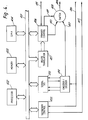
- a network interface communicate by way of a data bus 401 and comprise a processor 402, data memory 403 and direct memory access circuit 404. These elements may be a part of the user apparatus and are supplemented by a secondary control 405 and a primary control 406 which may be integral with the processor 402.
- the processor 402 If the processor 402 generates a data string for transmission by way of the network it is arranged to assemble the data string with a receiver address (which does not necessarily comprise the network route) and is arranged to store this information in a memory address in the data memory 403 by way of the bus 401.
- the processor 402 sets the direct memory access circuit 404 to point to the memory address and also sends an instruction to the primary control 406.
- the primary control 406 uses the direct memory access circuit 404 to transfer the receiver address from the memory 403 to a route translation device 407 (which may simply be a 'look up table' of a memory) to obtain a set of routing bits for the network.
- a route translation device 407 which may simply be a 'look up table' of a memory
- the primary control 406 By use of a control connection 411 the primary control 406 now causes an output switch 408 to set up a path between an input 410 from the primary control 406 to the output 409 which is connected to one of the inputs of the switching network.
- the primary control now commences a time out whilst forwarding the routing bits one at a time by way of the input 410 and the switch 408 to the network input with the necessary seize pulses (if any) inserted.
- the primary control On receipt of an acknowledgement signal the primary control ceases sending routing bits and causes a serial input/output device to use the direct memory access circuit to effect transfer of the data from the memory 403 by way of the bus 401 to itself.
- the serial input/ output device 413 effects a parallel to serial conversion of the data for transmission.
- the primary control 406 Immediately on completion of sending of the routing bits (that is on receipt of an acknowledge signal) the primary control 406 causes the output switch 408 to connect the output 40 9 to another input 412 by way of which the data is
- An encoder/decoder 414 in the present case acting as an encoder, commences demanding bits from the serial input/ output circuit 413 and on receiving each bit converts it as necessary and forwards the digits to the network.
- the primary control 406 awaits an acknowledgement of the message sent from the receiving apparatus which acknowledgement is received by way of an input 415. If an acknowledgement is not received within a prespecified period the primary control 406 may make further attempts to send the message in a similar manner. Should the system fail to transfer the message after a prespecified number of attempts the primary control 406 may be arranged to transfer a message failure signal to the processor 402 or to send a message by way of the network to an alarm or testing apparatus.
- acknowledge signals are available to the system either or both of which may be used.
- the success of a path set up may be indicated by the return of the clock signal on the reverse path by the receiving interface.
- For 'negative' acknowledging a concentrator in the network detecting contention may return a single clock pulse indicating failure of the message to pass.
- a combination of 'positive' and 'negative t acknowledgement may be used to reduce network holding time if contention occurs.
- Received messages are handled by the secondary control 405.
- the secondary control 404 detects a message on a forward path 416 of the secondary it is arranged to return an acknowledgement signal by way of a secondary reverse path 417.
- the incoming message is decoded by the encoder/decoder 414 and is transferred to the input/output 413 which carries out a serial to parallel conversion of the incoming data.
- the secondary control 405 will cause the message to be transferred as it is received by use of the direct memory access circuit 404 which is set up by the processor 402 to point to a specified address of the memory 403. It will be appreciated that a data string which contains too many bits for a single parallel transfer on the data bus 401 may be transferred 'n' bits at a time as each 'n' bits are received, the direct memory access circuit 404 being stepped on by the processor 402 or independantly as each 'n' bit word is transferred.
- switched forward and reverse data transmission paths Whilst as hereinbefore described only switched forward and reverse data transmission paths have been defined,it is here noted that a switched clock path is also provided to obviate the need for encoding data and clock signals for transmission and to simplify the logic of the distributors and concentrators.
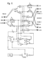
- the binary distributor is a simple circuit the operation of which requires little description.
- the clock path 501 When the clock path 501 is idle (that is there is no clock signal present) the node is periodically reset. However the resetting of the circuit is inhibited as soon as a clock signal is present on the clock path 501 and the first data bit is stored in a latch and used to determine which of two output channels (channel 0 or channel 1) is to be used. The selected channel is then enabled connecting the primary forward and reverse paths and the clock path to the appropriate secondary channel paths. As long as the clock path carries clock pulses the distributor will remain so enabled. When the clock path is idle for more than 1.4 microseconds the distributor resets itself.
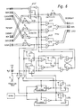
- both input clock paths must be in the idle state before the concentrator returns to its idle state (with both paths enabled through) to prevent part of a message which has been "lost” from falsely becoming attached to the end of a message which has successfully passed through the concentrator.
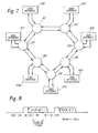
- nodes having both distributors and concentrators are arranged in the form of a loop as shown in Figure 7 to which reference is now made.
- seven user interfaces 701-707 are interconnected by way of a bothway transmission loop having one access point node 711-717 for each user interface.
- the network is made up of distributors and concentrators of the kind hereinbefore described and it will be apparent that every user interface 701-707 will have at least two routes through the network to every other user interface 701-707.
- the switched path comprises clock, forward and reverse transmission paths.
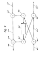
- a message on the anticlockwise transmission path 901 at one of the access points may be switched by a distributor 902 either on a through path 903 by way of a concentrator 904 to output 905 by use of output 902A or by way of output 902B to another concentrator 906 to a user interface 908.
- the output 902'B of the distributor 902' may be used to pass a message by way of the concentrator 906 to the user interface 9 0 8.
- a selector is used to select either the anticlockwise transmission path 905 by way of output 909A and the concentrator 904 or the clockwise transmission path 905' by way of output 909B and the concentrator 904'.
Landscapes
- Engineering & Computer Science (AREA)
- Computer Hardware Design (AREA)
- Theoretical Computer Science (AREA)
- Physics & Mathematics (AREA)
- General Engineering & Computer Science (AREA)
- Software Systems (AREA)
- Mathematical Physics (AREA)
- General Physics & Mathematics (AREA)
- Multimedia (AREA)
- Computer Networks & Wireless Communication (AREA)
- Signal Processing (AREA)
- Data Exchanges In Wide-Area Networks (AREA)
- Small-Scale Networks (AREA)
Applications Claiming Priority (2)
| Application Number | Priority Date | Filing Date | Title |
|---|---|---|---|
| GB838333519A GB8333519D0 (en) | 1983-12-16 | 1983-12-16 | Data signal switching systems |
| GB8333519 | 1983-12-16 |
Publications (2)
| Publication Number | Publication Date |
|---|---|
| EP0146275A2 true EP0146275A2 (fr) | 1985-06-26 |
| EP0146275A3 EP0146275A3 (fr) | 1987-04-15 |
Family
ID=10553372
Family Applications (1)
| Application Number | Title | Priority Date | Filing Date |
|---|---|---|---|
| EP84308072A Withdrawn EP0146275A3 (fr) | 1983-12-16 | 1984-11-21 | Système de commutation de données |
Country Status (4)
| Country | Link |
|---|---|
| US (1) | US4625306A (fr) |
| EP (1) | EP0146275A3 (fr) |
| CA (1) | CA1227556A (fr) |
| GB (2) | GB8333519D0 (fr) |
Cited By (13)
| Publication number | Priority date | Publication date | Assignee | Title |
|---|---|---|---|---|
| WO1987005724A3 (fr) * | 1986-03-18 | 1987-11-05 | Anamartic Ltd | Systeme d'adressage selectif pour modules de circuit |
| JPH01105641A (ja) * | 1987-10-19 | 1989-04-24 | Oki Electric Ind Co Ltd | パケット交換方式 |
| EP0312628A1 (fr) * | 1987-10-20 | 1989-04-26 | International Business Machines Corporation | Dispositif modulaire de commutation à grande vitesse pour le trafic en mode circuit et paquet |
| EP0229299A3 (en) * | 1985-12-12 | 1989-07-19 | American Telephone And Telegraph Company | A nonblocking self-routing packet and circuit switching network |
| EP0245996A3 (en) * | 1986-05-14 | 1989-12-13 | Northern Telecom Limited | Method of and switch for switching information |
| JPH0364141A (ja) * | 1989-08-01 | 1991-03-19 | Nec Corp | パケット交換機の出線バッファ優先度制御方式 |
| US5010542A (en) * | 1987-08-20 | 1991-04-23 | Siemens Aktiengesellschaft | Multi-stage switching network for light waveguides |
| EP0424979A2 (fr) | 1986-03-18 | 1991-05-02 | Anamartic Limited | Système d'adressage sélectif pour modules de circuit |
| JPH03241945A (ja) * | 1990-02-19 | 1991-10-29 | Nec Corp | クロスコネクト装置 |
| EP0405208A3 (en) * | 1989-06-29 | 1992-05-06 | International Business Machines Corporation | Multistage network with distributed pipelined control |
| FR2678794A1 (fr) * | 1991-07-04 | 1993-01-08 | Met | Concentration numerique. |
| EP0471256A3 (en) * | 1990-08-10 | 1993-08-04 | Hitachi, Ltd. | Atm switch and atm multiplexer |
| US6409836B1 (en) | 1996-11-29 | 2002-06-25 | Voith Sulzer Papiermaschinen Gmbh | Apparatus for direct or indirect application of a liquid or pasty coating medium onto a traveling material web, notably of paper or cardboard |
Families Citing this family (15)
| Publication number | Priority date | Publication date | Assignee | Title |
|---|---|---|---|---|
| DE3788577T2 (de) * | 1986-01-09 | 1994-07-07 | Nippon Electric Co | Paketvermitteltes Fernmeldenetz mit parallelen virtuellen Verbindungen zur Umweglenkung von Nachrichtenpaketen. |
| GB2189112B (en) * | 1986-04-10 | 1990-03-14 | Stc Plc | Automatic telecommunications switching system |
| ZA883232B (en) * | 1987-05-06 | 1989-07-26 | Dowd Research Pty Ltd O | Packet switches,switching methods,protocols and networks |
| US5222085A (en) * | 1987-10-15 | 1993-06-22 | Peter Newman | Self-routing switching element and fast packet switch |
| GB8724208D0 (en) * | 1987-10-15 | 1987-11-18 | Newman P | Self-routing switching element |
| US5245603A (en) * | 1987-10-15 | 1993-09-14 | Network Equipment Technologies, Inc. | High-speed determining unit for prioritizing and arbitrating among competing input signals |
| US5367518A (en) * | 1987-10-15 | 1994-11-22 | Network Equipment Technologies, Inc. | Self-routing switching element and fast packet switch |
| US5396491A (en) * | 1988-10-14 | 1995-03-07 | Network Equipment Technologies, Inc. | Self-routing switching element and fast packet switch |
| GB2227341A (en) * | 1989-01-18 | 1990-07-25 | Intel Corp | Message routing in a multiprocessor computer system |
| SE467079B (sv) * | 1990-09-19 | 1992-05-18 | Ellemtel Utvecklings Ab | Saett och anordning foer adressering i ett paketnaet |
| US5257266A (en) * | 1991-02-27 | 1993-10-26 | General Dynamics Corporation, Space Systems Division | Computer and communications systems employing universal direct spherics processing architectures |
| JPH0831856B2 (ja) * | 1991-08-16 | 1996-03-27 | インターナショナル・ビジネス・マシーンズ・コーポレイション | 故障信号搬送ラインを予備信号搬送ラインで置き換える装置及び方法 |
| ATE269616T1 (de) * | 2000-04-25 | 2004-07-15 | Nortel Networks Sa | Drahtloses telekommunikationssystem mit einer reduzierten verzögerung für die datenübermittlung |
| US9100313B1 (en) * | 2012-12-10 | 2015-08-04 | Cisco Technology, Inc. | Shared egress buffer in a multi-stage switch |
| US9965211B2 (en) | 2016-09-08 | 2018-05-08 | Cisco Technology, Inc. | Dynamic packet buffers with consolidation of low utilized memory banks |
Family Cites Families (8)
| Publication number | Priority date | Publication date | Assignee | Title |
|---|---|---|---|---|
| CH591190A5 (fr) * | 1975-04-25 | 1977-09-15 | Hasler Ag | |
| FR2420254A1 (fr) * | 1978-03-17 | 1979-10-12 | Anvar | Procede de routage d'informations dans un reseau de transmission de donnees numeriques et dispositif et reseau pour la mise en oeuvre de ce procede |
| FR2447652A1 (fr) * | 1979-01-24 | 1980-08-22 | Materiel Telephonique | Operateur pour reseau de commutation de donnees numeriques par paquets |
| US4307446A (en) * | 1979-05-02 | 1981-12-22 | Burroughs Corporation | Digital communication networks employing speed independent switches |
| US4237447A (en) * | 1979-05-02 | 1980-12-02 | Burroughs Corporation | Speed independent selector switch for digital communication networks |
| US4308613A (en) * | 1979-10-12 | 1981-12-29 | Chasek Norman E | Simplex, party-line electromagnetic data packet transmission system with a self seeking alternate routing capability |
| US4365292A (en) * | 1979-11-26 | 1982-12-21 | Burroughs Corporation | Array processor architecture connection network |
| US4498133A (en) * | 1981-12-10 | 1985-02-05 | Burroughs Corp. | Selector switch for a concurrent network of processors |
-
1983
- 1983-12-16 GB GB838333519A patent/GB8333519D0/en active Pending
-
1984
- 1984-11-21 EP EP84308072A patent/EP0146275A3/fr not_active Withdrawn
- 1984-11-23 GB GB08429681A patent/GB2151880B/en not_active Expired
- 1984-11-30 US US06/677,065 patent/US4625306A/en not_active Expired - Fee Related
- 1984-12-14 CA CA000470116A patent/CA1227556A/fr not_active Expired
Cited By (14)
| Publication number | Priority date | Publication date | Assignee | Title |
|---|---|---|---|---|
| EP0229299A3 (en) * | 1985-12-12 | 1989-07-19 | American Telephone And Telegraph Company | A nonblocking self-routing packet and circuit switching network |
| WO1987005724A3 (fr) * | 1986-03-18 | 1987-11-05 | Anamartic Ltd | Systeme d'adressage selectif pour modules de circuit |
| US5031139A (en) * | 1986-03-18 | 1991-07-09 | Anamartic Limited | Random address system for circuit modules |
| EP0424979A2 (fr) | 1986-03-18 | 1991-05-02 | Anamartic Limited | Système d'adressage sélectif pour modules de circuit |
| EP0245996A3 (en) * | 1986-05-14 | 1989-12-13 | Northern Telecom Limited | Method of and switch for switching information |
| US5010542A (en) * | 1987-08-20 | 1991-04-23 | Siemens Aktiengesellschaft | Multi-stage switching network for light waveguides |
| JPH01105641A (ja) * | 1987-10-19 | 1989-04-24 | Oki Electric Ind Co Ltd | パケット交換方式 |
| EP0312628A1 (fr) * | 1987-10-20 | 1989-04-26 | International Business Machines Corporation | Dispositif modulaire de commutation à grande vitesse pour le trafic en mode circuit et paquet |
| EP0405208A3 (en) * | 1989-06-29 | 1992-05-06 | International Business Machines Corporation | Multistage network with distributed pipelined control |
| JPH0364141A (ja) * | 1989-08-01 | 1991-03-19 | Nec Corp | パケット交換機の出線バッファ優先度制御方式 |
| JPH03241945A (ja) * | 1990-02-19 | 1991-10-29 | Nec Corp | クロスコネクト装置 |
| EP0471256A3 (en) * | 1990-08-10 | 1993-08-04 | Hitachi, Ltd. | Atm switch and atm multiplexer |
| FR2678794A1 (fr) * | 1991-07-04 | 1993-01-08 | Met | Concentration numerique. |
| US6409836B1 (en) | 1996-11-29 | 2002-06-25 | Voith Sulzer Papiermaschinen Gmbh | Apparatus for direct or indirect application of a liquid or pasty coating medium onto a traveling material web, notably of paper or cardboard |
Also Published As
| Publication number | Publication date |
|---|---|
| GB2151880A (en) | 1985-07-24 |
| US4625306A (en) | 1986-11-25 |
| EP0146275A3 (fr) | 1987-04-15 |
| CA1227556A (fr) | 1987-09-29 |
| GB2151880B (en) | 1987-05-13 |
| GB8333519D0 (en) | 1984-01-25 |
| GB8429681D0 (en) | 1985-01-03 |
Similar Documents
| Publication | Publication Date | Title |
|---|---|---|
| US4625306A (en) | Data signal switching systems | |
| EP0096097B1 (fr) | Méthode et dispositif pour contrôler l'accès à un réseau de communication | |
| US4380063A (en) | Flow control mechanism for block switching nodes | |
| CA1252168A (fr) | Reseau de communication | |
| US4514843A (en) | Packet switched communication system comprising collision avoidance means | |
| US4573044A (en) | Two channel looped communication system having rerouting and folded loop capabilities | |
| EP0123507B1 (fr) | Système et appareil de communication de données | |
| US5291490A (en) | Node for a communication network | |
| EP0229299A2 (fr) | Réseau de commutation par paquets et circuits sans blocage autocherchant | |
| US5285449A (en) | Protocol for hybrid local area networks | |
| US4285064A (en) | TDMA Satellite communication system | |
| JPS6276840A (ja) | ノ−ド装置 | |
| US4340775A (en) | Apparatus and method for controlling a modular telecommunication system | |
| US4794590A (en) | Communication network control system | |
| US3859465A (en) | Data transmission system with multiple access for the connected users | |
| US4858228A (en) | Communication system employing multi-conjunction architecture | |
| JP2529862B2 (ja) | 多線条リング形ネットワ−ク | |
| JPH03210864A (ja) | レベル2信号処理装置 | |
| JPH0771099B2 (ja) | トークンパッシングデータ通信方式の端末装置 | |
| JPH0292042A (ja) | 情報パケットヘッダ変換方式 | |
| JPS63316539A (ja) | マルチキャスト通信装置における再送制御装置 | |
| JPH0453336A (ja) | 不定形通信網のノード装置 | |
| JPH0744560B2 (ja) | 蓄積型星状網 | |
| JPS6158352A (ja) | 通信監視装置選択方式 | |
| JPH04367145A (ja) | 伝送ルートの選択方式 |
Legal Events
| Date | Code | Title | Description |
|---|---|---|---|
| PUAI | Public reference made under article 153(3) epc to a published international application that has entered the european phase |
Free format text: ORIGINAL CODE: 0009012 |
|
| AK | Designated contracting states |
Designated state(s): DE FR SE |
|
| PUAL | Search report despatched |
Free format text: ORIGINAL CODE: 0009013 |
|
| AK | Designated contracting states |
Kind code of ref document: A3 Designated state(s): DE FR SE |
|
| 17P | Request for examination filed |
Effective date: 19870513 |
|
| 17Q | First examination report despatched |
Effective date: 19881201 |
|
| RAP1 | Party data changed (applicant data changed or rights of an application transferred) |
Owner name: GEC PLESSEY TELECOMMUNICATIONS LIMITED |
|
| STAA | Information on the status of an ep patent application or granted ep patent |
Free format text: STATUS: THE APPLICATION IS DEEMED TO BE WITHDRAWN |
|
| 18D | Application deemed to be withdrawn |
Effective date: 19891019 |
|
| RIN1 | Information on inventor provided before grant (corrected) |
Inventor name: NEWMAN, PETER |