EP0146309A2 - Machine à laver un bloc - Google Patents
Machine à laver un bloc Download PDFInfo
- Publication number
- EP0146309A2 EP0146309A2 EP84308422A EP84308422A EP0146309A2 EP 0146309 A2 EP0146309 A2 EP 0146309A2 EP 84308422 A EP84308422 A EP 84308422A EP 84308422 A EP84308422 A EP 84308422A EP 0146309 A2 EP0146309 A2 EP 0146309A2
- Authority
- EP
- European Patent Office
- Prior art keywords
- passageway
- washing fluid
- washer
- flitch
- nozzles
- Prior art date
- Legal status (The legal status is an assumption and is not a legal conclusion. Google has not performed a legal analysis and makes no representation as to the accuracy of the status listed.)
- Granted
Links
- 238000005406 washing Methods 0.000 claims abstract description 63
- 239000012530 fluid Substances 0.000 claims abstract description 51
- 239000007921 spray Substances 0.000 claims description 10
- 238000004064 recycling Methods 0.000 claims description 4
- 238000007599 discharging Methods 0.000 claims description 3
- XLYOFNOQVPJJNP-UHFFFAOYSA-N water Substances O XLYOFNOQVPJJNP-UHFFFAOYSA-N 0.000 description 24
- 239000004576 sand Substances 0.000 description 13
- 239000000463 material Substances 0.000 description 12
- 239000002689 soil Substances 0.000 description 11
- 230000003134 recirculating effect Effects 0.000 description 5
- 229920002522 Wood fibre Polymers 0.000 description 3
- 238000001914 filtration Methods 0.000 description 3
- 125000006850 spacer group Chemical group 0.000 description 3
- 229910001220 stainless steel Inorganic materials 0.000 description 3
- 239000010935 stainless steel Substances 0.000 description 3
- 239000002025 wood fiber Substances 0.000 description 3
- 238000010411 cooking Methods 0.000 description 2
- 238000012423 maintenance Methods 0.000 description 2
- 239000002184 metal Substances 0.000 description 2
- 238000011084 recovery Methods 0.000 description 2
- 238000005299 abrasion Methods 0.000 description 1
- 238000009833 condensation Methods 0.000 description 1
- 230000005494 condensation Effects 0.000 description 1
- 238000010276 construction Methods 0.000 description 1
- 229910003460 diamond Inorganic materials 0.000 description 1
- 239000010432 diamond Substances 0.000 description 1
- 238000010438 heat treatment Methods 0.000 description 1
- 239000007788 liquid Substances 0.000 description 1
- 238000002360 preparation method Methods 0.000 description 1
- 239000007787 solid Substances 0.000 description 1
- 238000005507 spraying Methods 0.000 description 1
- 230000032258 transport Effects 0.000 description 1
- 239000002699 waste material Substances 0.000 description 1
- 239000002023 wood Substances 0.000 description 1
Images



Classifications
-
- B—PERFORMING OPERATIONS; TRANSPORTING
- B08—CLEANING
- B08B—CLEANING IN GENERAL; PREVENTION OF FOULING IN GENERAL
- B08B3/00—Cleaning by methods involving the use or presence of liquid or steam
- B08B3/02—Cleaning by the force of jets or sprays
- B08B3/022—Cleaning travelling work
-
- B—PERFORMING OPERATIONS; TRANSPORTING
- B27—WORKING OR PRESERVING WOOD OR SIMILAR MATERIAL; NAILING OR STAPLING MACHINES IN GENERAL
- B27L—REMOVING BARK OR VESTIGES OF BRANCHES; SPLITTING WOOD; MANUFACTURE OF VENEER, WOODEN STICKS, WOOD SHAVINGS, WOOD FIBRES OR WOOD POWDER
- B27L1/00—Debarking or removing vestiges of branches from trees or logs; Machines therefor
- B27L1/14—Debarking or removing vestiges of branches from trees or logs; Machines therefor using jets of fluid
-
- B—PERFORMING OPERATIONS; TRANSPORTING
- B27—WORKING OR PRESERVING WOOD OR SIMILAR MATERIAL; NAILING OR STAPLING MACHINES IN GENERAL
- B27L—REMOVING BARK OR VESTIGES OF BRANCHES; SPLITTING WOOD; MANUFACTURE OF VENEER, WOODEN STICKS, WOOD SHAVINGS, WOOD FIBRES OR WOOD POWDER
- B27L5/00—Manufacture of veneer ; Preparatory processing therefor
Definitions
- This invention relates to apparatus for processing logs and flitches in preparation for cutting veneer slices from the flitches.
- Spray devices comprising two coaxial cylinders are also known.
- the washers of U. S. Patents 876,301; 3,858,860; and 3,986,710.
- U. S. Patent 3,858,860 disclose the use of nozzles in the inner wall of an inner cylinder to direct a spray of liquid onto an object passing through the inner cylinder.
- the nozzles of such prior art systems typically are permanently located in the inner wall of the inner cylinder.
- a washer for a flitch or the like comprises means defining a passageway open at an entry end and an exit end, means for conveying a flitch through the passageway from the entry end to the exit end, means defining a plurality of nozzles along the walls of the passageway for discharging a washing fluid into the passageway, and means for supplying washing fluid to the nozzles.
- the means defining a passageway comprises a cylinder.
- the cylinder is a generally right circular cylinder.
- the means defining a plurality of nozzles along the walls of the passageway comprises means defining openings through the passageway, and a plurality of nozzles for engaging the opening. Additionally, according to the invention, a plurality of plugs are provided for engaging the openings. The nozzles and plugs engage the openings in a selected pattern to provide a selected spray pattern for the washing fluid into the passageway.
- the means for supplying washing fluid to the nozzles comprises a second cylinder, the axis of which extends parallel to the axis of the first cylinder.
- Means are provided for closing the spaces between the ends of the first and second cylinders to define a volume between them.
- Means providing a supply opening through the second cylinder and into the volume to supply washing fluid to the nozzles are also provided.
- the means for closing the spaces between the ends of the first and second cylinders to define the volume between 'them comprises bulkheads.
- the washer for a flitch includes means for recycling said washing fluid, means for trapping debris beneath the means for conveying a flitch and means for conveying the trapped debris away from the washer for disposal.
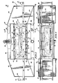
- a flitch washer 20 includes an inner, generally right circular cylinder 22 defining a passageway 24 through which a flitch 25 is conveyed on a conveyor 26.
- the flitch 25 passes along the conveyor 26 from an entry end 28 of the passageway 24 to an exit end 30 thereof. While in the passageway 24, the flitch 25 is washed thoroughly by a washing fluid, such as recirculating water, expelled under relatively low pressure and at high volume from nozzles 32 screw-threaded (Fig.6) into openings 33 provided in the side wall of the inner cylinder 22.
- a washing fluid such as recirculating water
- the nozzle openings 33 are formed into one or more coaxial helical patterns.
- the single dots in Fig. 2 illustrate the positions of the nozzle openings 33 on the side of the cylinder 22 illustrated in the elevational view of Fig.
- the patterns of four dots illustrate the positions of the nozzle openings 33 on the side of the cylinder 22 cut away in the sectional elevation of Fig. 2 for purposes of illustration.
- the end, generally vertically extending rows 34 of nozzles 32 can be provided with nozzles which airect their sprays not only inwardly toward the axis of cylinder 22, but also inwardly toward the center of the longitudinal extent of'the cylinder 22, as best illustrated at 35 in Fig. 2.
- the flitch washer 20 also includes an outer, generally right circular cylinder 36 which is attached intermediate its ends by rod-like spacer/supports 37 to the intermediate regions of the inner, generally right circular cylinder 22 to form a volume 42.
- Outer cyclinder 36 is also attached at its ends by bulkheads 38, 40 to the ends of cylinder 22.
- Cylinder 36 is provided with a washing fluid supply opening 44 (Fig. 5) which is coupled by means of a conduit 46 to a high-volume, lowpressure pump 48 which pumps washing fluid into the volume 42.
- a well conduit 50 communicates 'by means of a return line 52 to the inlet to pump 48.
- the entry end 28 and exit end 30 of passageway 24 are provided with respective entry end hood 60 and exit end hood 62.
- the downwardly and outwardly inclined inner floors 64 of entry end hood 60 and exit end hood 62 illustratively are constructed from a grate-type material, such as expanded metal, to permit some filtering and the drainage of washing fluid from the entry and exit ends 28, 30 of passageway 24 and from the flitches which exit from exit end 30 on conveyor 26 to be collected in regions 65 of hoods 60, 62 for recovery in well 50 and recirculation through the return line 52 to the pump 48.
- a spray curtain 69 (Fig. 2) can be added to the outer opening of each of hoods 60, 62 as needed to prevent washing fluid from splashing or spraying beyond the hood 60, 62 openings.
- a filter 67 (Fig. 5) can be provided in the return line 52 to filter bark, soil, sand and other debris from the washing fluid prior to entry to the pump 48 inlet.
- the entry end hood 60 and exit end hood 62 also communicate with conduits 66 (Fig. 2), and through conduits 66 and a blower 68 with a conduit 70 (Fig. 5) which leads to a condenser room 72. Washing fluid which has vaporized and collects in the entry end hood 60 and exit end hood 62 is recovered and circulated through conduits 66, 70 under the influence of the blower 68 for condensation and return to the recirculating system for pump 48.
- the large volume of water flowing in the flitch washer creates a considerable vacuum within the flitch washer and draws off the water vapor with the water which is being recirculated.
- the vapor recovery fan 68 can be removed from the system if a sufficiently high volume of water is used.
- a central conveyor portion which lies within the passageway 24, comprises a plurality of generally uniformly spaced rollers 78 (Fig. 6) constructed from a material, such as rubber, which is generally non-reactive with the washing fluid and other materials with which the washing fluid becomes contaminated during use.
- Each roller 78 is mounted on a drive shaft 80, one end of which is rotatably mounted, as best illustrated in Fig. 5, from the interior wall of cylinder 22.
- the other end of each drive shaft 80 extends through a passageway 82 which itself extends through openings 84, 86, provided in the inner and outer cylinders 22, 36, respectively.
- Passageway 82 is provided with bushings 88 to mount the drive shaft rotatably within the passageway 82.
- the ends of the drive shafts 80 which extend beyond the outer bushing 88 are provided with sprockets 90.
- the sprockets 90 are all housed in an elongated common guard 92 which includes space for a drive chain (not shown) to be trained about the sprockets 90 and about a drive sprocket for the rollers 78. This drive sprocket (not shown) is rotated to drive flitches 25 along the conveyor 26.
- An illustrative system constructed according to this embodiment had a total length of 16 feet (4.88 meters), including entry and exit end hood 60, 62, lengths of 4 feet (1.22 meters).
- the width of each of the entry and exit end hoods 60, 62, as viewed in Fig. 4 was also 4 feet (1.22 meters).
- the diameter of the passageway 24 illustratively was 30 inches (76.2 centimeters).
- the height of the passageway 24 from the tops of the rollers 78 to the top of the passageway 24 illustratively was 23 inches (98.4 centimeters).
- the diameter of the outer cylinder 36 illustratively was 39 inches (99 centimeters).
- the width of the entry and exit conveyor portions 74, 76 was 32 inches (81 centimeters), and the width of the conveyor 26 in the roller 78 region was 24 inches (61 centimeters).
- Conduit 46 had a diameter of about 6 inches (15.2 centimeters)
- return line 52 had a width of about 6 inches (15.24 centimeters) and a height of about 8 inches (20.3 centimeters).
- Conduit 66 had a diameter of about 8 inches (20.3 centimeters) and conduit 70 had a diameter of about 12 inches (30.5 centimeters).
- the height of the washer 20 to the top of the entry and exit hoods 60, 62 was 72 inches (1.83 meters), and the height to the top of the conveyor 26 was 32 inches (81.3 centimeters).
- Recirculating water was the washing fluid.
- Pump 48 supplied water at 150 pounds per square inch at 800 gallons per minute and 160° F.
- the washer was constructed generally from stainless steel.
- a flitch washer 120 includes an inner, generally right circular cylinder 122 defining a passageway 124 through which a flitch 125 is conveyed on a conveyor 126.
- the flitch 125 passes along the conveyor 126 from an entry end 128 of the passageway 124 to an exit end 130 thereof. While in the passageway 124, the flitch 125 is washed thoroughly by a washing fluid, such as recirculating water, expelled under relatively low pressure and at high volume from nozzles 132 screw-threaded (Fig. 11) into openings 133 provided in the side wall of the inner cylinder 122.
- a washing fluid such as recirculating water
- the nozzle openings 133 are formed into one or more coaxial helical patterns.
- the end, generally vertically extending rows 134 of nozzles 132 can be provided with nozzles which direct their sprays not only inwardly toward the axis of cylinder.122, but also inwardly toward the center of the longitudinal extent of the cylinder 122, as best illustrated at 135 in Fig. 8.
- the flitch washer 120 also includes an outer, generally right circular cylinder 136 which is attached intermediate its ends by rod-like spacer/supports 137 to the intermediate regions of the inner, generally right circular cylinder 122 to form a volume 142.
- Outer cylinder 136 is also attached at its ends by bulkheads 138, 140 to the ends of cylinder 122.
- Cylinder 136 is provided with a washing fluid supply opening 144 (Figs. 8-9) which is coupled by means of a conduit 146 to a high-volume, low-pressure pump 148 which pumps washing fluid into the volume 142.
- a well 150 communicates by means of a return line 152 to the inlet to pump 148.
- the entry end 128 and exit end 130 of passageway 124 are provided with respective entry end hood 160 and exit end hood 162.
- the downwardly and outwardly inclined inner floors 164 of entry end hood 160 and exit end hood 162 illustratively are constructed from a grate-type material, such as expanded metal, to permit some filtering and the drainage of washing fluid from the entry and exit ends 128, 130 of passageway 124 and from the flitches which exit from exit end 130 on conveyor 126 to be collected in well 150 for recirculation through the return line 152 to the pump 148.
- a somewhat diamond shaped drain 165 is provided through the walls of both of cylinders 122, 136 at the bottom center of passageway 124 for this purpose.
- the shape of the drain 165 also helps channel the high volume of water into the two ends of the volume 142.
- An additional filter 167 (Fig. 9) is provided in the return line 152 to help filter bark, soil, sand and other debris from the washing fluid prior to entry to the pump 148 inlet.
- a central conveyor portion which lies within the passageway 124, comprises a plurality of generally uniformly spaced rollers 178 (Fig. 11) constructed from a material which is generally non-reactive with the washing fluid and other materials 'with which the washing fluid becomes contaminated during use.
- Each roller 178 is mounted on a drive shaft 180, one end of which is rotatably mounted, as best illustrated in Fig. 10, from the interior wall of cylinder 122.
- the other end of each drive shaft 180 extends through a passageway 182 which itself extends through openings 184, 186, provided in the inner and outer cylinders 122, 136, respectively.
- Passageway 182 is provided with bushings 188 to mount the drive shaft rotatably within the passageway 182.
- the ends of the 3rive shafts 180 which extend beyond the outer bushing 188 are provided with sprockets 190.
- the sprockets 190 are housed in an elongated common guard 192 which includes space for a drive chain (not shown) to be trained about the sprockets 190 and about a drive sprocket for the rollers 178. This drive sprocket (not shown) is rotated to drive flitches 125 along the conveyor 126.
- An illustrative system constructed according to this embodiment had a total length of 14 feet (4.27 meters), including entry and exit end hood 160, 162, lengths of 3 feet (91.4 centimeters).
- the width of each of the entry and exit end hoods 160, 162, as viewed in Fig. 10 was 42 inches (1.07 meters).
- the diameter of the passageway 124 illustratively was 30 inches (76.2 centimeters).
- the height of the passageway 124 from the tops of the rollers 178 to the top of the passageway 124 illustratively was 23 inches (98.4 centimeters).
- the diameter of the outer cylinder 136 illustratively was 39 inches (99 centimeters).
- the width of the entry and exit conveyor portions 174, 176 was 32 inches (81 centimeters), and the width of the conveyor 126 in the roller 178 region was 24 inches (61 centimeters).
- Conduit 146 had a diameter of about 6 inches (15.2 centimeters), return line 152 had a diameter of about 8 inches (20.3 centimeters).
- the height of the washer 120 to the top of the entry and exit hoods 160, 162 was 60 inches (1.52 meters), and the height to the top of the conveyor 126 was 32 inches (81.3 centimeters).
- Recirculating water was the washing fluid.
- Pump 148 supplied water at 150 pounds per square inch at 800 gallons per minute and 160° F.
- One system according to the invention recycles 4,000 gallons (15147.5'kg) at 800 gallons/min, for three days of two shift-per-day operation. With this amount of water recycling at this rate, 1,200 flitches can be washed.
- the inclined filters 164 at the entry and exit ends of the flitch washer are cleared of wood fiber about twice a day.
- the filter 167 in the recycle water storate vat is cleaned once every three days, when the recycle water is renewed.
- the present system operates at a pressure of at most one-tenth that of the prior art systems, or 200 pounds/in 2 (1.38 x 10 6 nt/m 2 ). Combined with the much lower pressure washing, the present system uses a very high volume of water, which cannot be achieved with >prior art systems using small, high-pressure nozzles.
- the high volume of water used by the present invention pushes the flitches down onto the conveyor system to assure that the flitches are driven positively by the conveyor system drive through the washer.
- the flitch washers of the present invention train sprays of water on the ends of the flitches at the inlet and outlet ends of the flitch washer, the ends of the flitches are cleaned adequately and do not need to be removed and discarded, as is required with prior art systems, to place the flitches in condition for slicing.
- the nozzles 132 in the end, generally vertically extending rows 134 may be specially configured with hoods 200, Fig. 12, which deflect the washing fluid sprays from these nozzles 132 inwardly into the flitch washer, rather than straight across diameters of cylinder 122 in curtain-like fashion.
- stiff wire brushes 202 are provided on the inlet end 204 of a flitch washer.
- Means such as motors 206 are provided for driving the brushes 202 to rotate against the surfaces 208 of the flitches 210 which pass through the washer.
- Some of the jets 132 of the type illustrated in Fig. 12 at the inlet end 204 of the washer are turned so as to be trained upon the brushes 202 to keep wood fibers and debris removed from the flitches 210 by the brushes 202 from accumulating on the brushes 202.
- Prior art high pressure washing jets with carbide tips are expensive, costing about $60 apiece. Even jets with carbide tips wear out from grit and sand abrasion because of the high pressure at which water is forced through them in such prior art systems.
- the jets 32, 132 of the present invention are constructed from stainless steel and have rather larger diameter jet openings (approximately one-eighth inch --3.2 mm) than prior art jets. This size is perfectly acceptable at the lower pressure of the present invention because of the high volume of water which is circulated through the system. If sand, grit, soils and the like wear on the jets 32, 132, such wear is perfectly acceptable since it serves only to make the nozzle openings larger and permit water to circulate through the system at a higher rate.
- a flitch washer 220 includes an outer, generally right circular cylinder 236 which is attached intermediate its ends by rod-like spacer/supports 237 to the intermediate regions of an inner, generally right circular cylinder 222 to form a volume 242.
- Outer cylinder 236 is also attached at its ends by bulkheads 238, 240 to the ends of cylinder 222.
- Cylinder 236 is provided with a washing fluid supply opening 244 (Figs. 14, 17) which is coupled by means of a conduit (not shown) to a high-volume, low-pressure pump 246 (Figs. 15, 17) which pumps washing fluid into the volume 242.
- a well 250 communicates by means of a line 249 (Figs. 15, 17) to the inlet to the high-volume, 'low-pressure pump 246.
- the wall of well 250 is constructed from a durable material which is non-reactive with the washing fluid and other materials with which the washing fluid becomes contaminated during use.
- a heavy-guage corrugated sheet stainless steel is )illustrated in this embodiment.
- the well 250 includes a sand trap 251 in the form of a solid baffle, and a heating coil 253 that is thermostatically controlled.
- Well 250 includes a filter screen 257 extending upward from the top of trap 251 to prevent large floating material that is not trapped by trap 251 from entering the recirculation system.
- the entry end 228 and exit end 230 of a flitch passageway 224 are provided with respective entry end hood 260 and exit end hood 262.
- Hoods 260, 262 are provided with V-grooved wheels 259 which permit them to roll on inverted V-shaped tracks 261 provided on the flat top edge surface 263 of well 250.
- Hoods 260, 262 aid in preventing the escape of, and help to collect, washing fluid in well 250 for recirculation.
- a somewhat oval-shaped drain 265 is provided through the walls of both cylinders 222, 236 at the bottom center of passageway 224 for this purpose.
- the orientation of the drain 265, with its long axis extending generally circumferentially around the cylinders 222, 226, also helps channel the high volume of water into the two ends of the volume 242.
- the conveyor 226 includes a main conveyor section 277, which extends the entire length of washer 220.
- Conveyor section 277 includes a pair of spaced chains 280 between which extend, at equal intervals, circular cross-section rods 278.
- Rods 278 are constructed from a material which is generally non-reactive with the washing fluid and other materials with which the washing fluid becomes contaminated during use.
- Each continuous chain 280 is trained about a respective pair of sprockets 282, 294 at each end of the washer 220.
- the sprockets 282 and 294 include spaced notches 286 about their peripheries to engage rods 278 and drive flitches 225 along conveyor section 277 and through the washer 220.
- Sprockets 282 are driven by a motor 288 (Fig. 15).
- the conveyor 226 also includes an exit conveyor portion 276 with rotably mounted rollers 292, each of which includes a drive sprocket 295 at one end.
- a drive chain 290 is trained about the sprocket 295 of the end roller 292 nearest sprockets 282.
- the flitch 225 is carried by the exit conveyor 276 to a transversely extending off-loading conveyor 296 that includes a plurality of conveyor chains 298 trained about respective sprockets 299 and driven from a common shaft 300.
- the conveyor chains 298 drive the flitch 225 transverse to conveyor 276 off conveyor 276.
- a grid 302 extends along the entire length of washer 220 below and adjacent to conveyor 277.
- the grid includes a plurality of longitudinally extending members 304 that are somewhat triangular in cross section (see Fig. 16) and a plurality of transverse, supporting members 306 that have generally the same cross-section.
- the members 304, 306 are welded or otherwise joined to form grid 302 beneath conveyor 277.
- the members 304 of grid 302 are sufficiently closely spaced to prevent larger pieces of bark and other such debris from filtering down into well 250.
- Rods 278 are provided with longitudinally extending rubber wipers 303. Wipers 303 are fitted by sliding them into longitudinally extending slots in the sidewalls of rods 278.
- Conveyor 308 includes an elevator section 310 (Fig. 17) to permit use of a large refuse container of several commercially available types known as "dumpsters," facilitating waste removal.
Landscapes
- Life Sciences & Earth Sciences (AREA)
- Engineering & Computer Science (AREA)
- Wood Science & Technology (AREA)
- Forests & Forestry (AREA)
- Manufacturing & Machinery (AREA)
- Cleaning By Liquid Or Steam (AREA)
- Cleaning In General (AREA)
Applications Claiming Priority (4)
| Application Number | Priority Date | Filing Date | Title |
|---|---|---|---|
| US06/562,460 US4874003A (en) | 1983-12-16 | 1983-12-16 | Flitch washer |
| US562460 | 1983-12-16 | ||
| US613276 | 1984-05-24 | ||
| US06/613,276 US4821754A (en) | 1983-12-16 | 1984-05-24 | Flitch washer |
Publications (3)
| Publication Number | Publication Date |
|---|---|
| EP0146309A2 true EP0146309A2 (fr) | 1985-06-26 |
| EP0146309A3 EP0146309A3 (en) | 1986-07-23 |
| EP0146309B1 EP0146309B1 (fr) | 1990-04-11 |
Family
ID=27072959
Family Applications (1)
| Application Number | Title | Priority Date | Filing Date |
|---|---|---|---|
| EP84308422A Expired EP0146309B1 (fr) | 1983-12-16 | 1984-12-04 | Machine à laver un bloc |
Country Status (4)
| Country | Link |
|---|---|
| US (1) | US4821754A (fr) |
| EP (1) | EP0146309B1 (fr) |
| CA (1) | CA1271951A (fr) |
| DE (1) | DE3481899D1 (fr) |
Cited By (2)
| Publication number | Priority date | Publication date | Assignee | Title |
|---|---|---|---|---|
| FR2643577A1 (fr) * | 1989-02-28 | 1990-08-31 | Tecnal | Installation auto-nettoyable pour le lavage automatique et en continu d'accessoires utilises dans l'industrie agro-alimentaire |
| WO2008151627A1 (fr) * | 2007-06-15 | 2008-12-18 | Troels Jakobsen | Système de lavage pour emballages récupérables et réutilisables et procédé d'alimentation en emballages du système |
Families Citing this family (5)
| Publication number | Priority date | Publication date | Assignee | Title |
|---|---|---|---|---|
| US4985956A (en) * | 1989-06-19 | 1991-01-22 | Staalkat B.V. | Washing machine vapor exhaust |
| US5419349A (en) * | 1993-02-09 | 1995-05-30 | Emerson Electric Co. | Portable small parts washer |
| US6938625B2 (en) * | 2002-11-18 | 2005-09-06 | Timothy L. Stalp | Load sensing system |
| IT201800010811A1 (it) * | 2018-12-05 | 2020-06-05 | Iwt Srl | Sistema di trattamento del liquido di risulta del lavaggio, adattato per applicazione in macchina di lavaggio di tipo continuo Tunnel per il settore della Ricerca Preclinica Farmaceutica |
| WO2021077195A1 (fr) * | 2019-10-25 | 2021-04-29 | Northern Mat & Bridge (Gp) Ltd. | Système de lavage de tapis |
Family Cites Families (39)
| Publication number | Priority date | Publication date | Assignee | Title |
|---|---|---|---|---|
| US1790756A (en) * | 1931-02-03 | Hose washer | ||
| US876301A (en) * | 1907-08-30 | 1908-01-07 | Samuel Cunningham | Washer for fire-hose. |
| US1087959A (en) * | 1913-11-03 | 1914-02-24 | Ernest Lisherness | Device for removing bark from logs, limbs of trees, and slabs. |
| US1609474A (en) * | 1925-07-22 | 1926-12-07 | Herbert W Guettler | Log washer |
| US1661356A (en) * | 1926-09-15 | 1928-03-06 | Wedworth V Baker | Washing machine |
| US1910497A (en) * | 1930-01-02 | 1933-05-23 | American Foundry Equip Co | Sand blast gun |
| US2097529A (en) * | 1934-12-20 | 1937-11-02 | Advance Engineering Company | Filter |
| US2140287A (en) * | 1936-06-15 | 1938-12-13 | Herbert W Guettler | Combined barking and washing drum |
| DE878103C (de) * | 1939-05-12 | 1953-06-01 | Haindl Sche Papierfabriken G | Vorrichtung zur Entrindung von Faserholz |
| US2261560A (en) * | 1940-02-06 | 1941-11-04 | Pellas | Method and apparatus for removing coffee beans from the berry |
| US2338136A (en) * | 1940-08-03 | 1944-01-04 | Allis Chalmers Mfg Co | Log barker and cleaner |
| US2328545A (en) * | 1941-02-24 | 1943-09-07 | Harry E Bukowsky | Hydraulic log-barking machine |
| US2394514A (en) * | 1942-12-03 | 1946-02-05 | American Car & Foundry Co | Process and apparatus for scaling hot metal objects |
| US2422757A (en) * | 1944-01-17 | 1947-06-24 | Frank H Swift | Hydraulic barker |
| US2616437A (en) * | 1946-08-31 | 1952-11-04 | Gen Electric | Quenching device for horizontally moving articles |
| US2576861A (en) * | 1948-11-18 | 1951-11-27 | Allis Chalmers Mfg Co | Hydraulic barker with multiple nozzle oscillating linkage |
| US2615481A (en) * | 1950-11-10 | 1952-10-28 | Frederick W Horstkotte | Oscillating manifold hydraulic log barker |
| US2682185A (en) * | 1950-11-14 | 1954-06-29 | Valley Forging Company | Forging machine |
| US2687152A (en) * | 1951-11-15 | 1954-08-24 | Hansel Sydney | Hydraulic log-barking apparatus having opposed slit-nozzles and log-aligning conveyers |
| US2664929A (en) * | 1953-03-17 | 1954-01-05 | Simons Howard Allan | Hydraulic log-barker having logholddown rollers and confronting rotary spray heads |
| US2738814A (en) * | 1954-10-20 | 1956-03-20 | Jackson Ind Inc | Hydraulic slab debarker |
| US2809683A (en) * | 1955-06-01 | 1957-10-15 | Hoiss Anton | Hydraulic log-peeler having a barkslitting nozzle and a bank of barkremoving nozzles |
| US2799308A (en) * | 1955-11-16 | 1957-07-16 | Terry Machinery Company Ltd | Debarking method and apparatus involving alternate high and lowpressure zones |
| US3570504A (en) * | 1968-10-01 | 1971-03-16 | Buckbee Mears Co | Washing and drying apparatus |
| US3709268A (en) * | 1969-11-06 | 1973-01-09 | R Tuuha | Drum barker |
| US3633593A (en) * | 1970-03-11 | 1972-01-11 | Jasper Corp The | Apparatus for cleaning log members |
| US3858860A (en) * | 1972-03-02 | 1975-01-07 | Armco Steel Corp | Pipe quench head |
| US3827097A (en) * | 1973-02-26 | 1974-08-06 | R Hamann | Device for washing and coiling hoses |
| CA982031A (en) * | 1973-08-02 | 1976-01-20 | Said Clement Ratelle | Log cleaning and barking |
| FR2284688A1 (fr) * | 1974-09-11 | 1976-04-09 | Creusot Loire | Dispositif de degraissage au defile de produits longs tels que des profiles metalliques |
| FI283374A7 (fr) * | 1974-09-27 | 1976-03-28 | Kone Oy | |
| US3986710A (en) * | 1975-06-19 | 1976-10-19 | Park-Ohio Industries, Inc. | Quench unit for inductively heated workpieces |
| CA1017231A (fr) * | 1975-08-21 | 1977-09-13 | Clement Ratelle | Ecorceuse et nettoyeuse de grumes |
| DE2710005C2 (de) * | 1977-03-08 | 1982-07-15 | Montanus Industrieanlagen Gmbh, 4300 Essen | Magnetfilteranlage |
| FR2419773A1 (fr) * | 1978-03-13 | 1979-10-12 | Burton Corblin | Perfectionnements apportes aux installations pour le lavage d'ustensiles utilises dans les industries alimentaires, notamment en industrie laitiere |
| SU719666A1 (ru) * | 1978-07-03 | 1980-03-05 | Научно-исследовательский институт технологии машиностроения | Фильтр дл непрерывной очистки жидкости |
| US4243527A (en) * | 1979-03-29 | 1981-01-06 | Martin Leonard | Particulate material separator and method |
| DE2938439A1 (de) * | 1979-09-22 | 1981-04-23 | Martin 8851 Mertingen Dietrich | Verfahren und vorrichtung zur feldreinigung von rodungsfruechten |
| JPS6028544B2 (ja) * | 1980-11-12 | 1985-07-05 | ブンリ工業株式会社 | マグネチックベルトコンベア式分離装置 |
-
1984
- 1984-05-24 US US06/613,276 patent/US4821754A/en not_active Expired - Fee Related
- 1984-12-04 EP EP84308422A patent/EP0146309B1/fr not_active Expired
- 1984-12-04 DE DE8484308422T patent/DE3481899D1/de not_active Expired - Lifetime
- 1984-12-14 CA CA000470140A patent/CA1271951A/fr not_active Expired
Cited By (2)
| Publication number | Priority date | Publication date | Assignee | Title |
|---|---|---|---|---|
| FR2643577A1 (fr) * | 1989-02-28 | 1990-08-31 | Tecnal | Installation auto-nettoyable pour le lavage automatique et en continu d'accessoires utilises dans l'industrie agro-alimentaire |
| WO2008151627A1 (fr) * | 2007-06-15 | 2008-12-18 | Troels Jakobsen | Système de lavage pour emballages récupérables et réutilisables et procédé d'alimentation en emballages du système |
Also Published As
| Publication number | Publication date |
|---|---|
| EP0146309B1 (fr) | 1990-04-11 |
| EP0146309A3 (en) | 1986-07-23 |
| US4821754A (en) | 1989-04-18 |
| DE3481899D1 (de) | 1990-05-17 |
| CA1271951A (fr) | 1990-07-24 |
Similar Documents
| Publication | Publication Date | Title |
|---|---|---|
| DE69327842T2 (de) | Verfahren und vorrichtung zur reinigung von in einer trommel transversal rotierenden zylindrischen bauteilen während einer nassbehandlung | |
| US5979473A (en) | Method and apparatus for washing fruit | |
| KR20120013077A (ko) | 야채류 가공장치 | |
| CN216271666U (zh) | 一种传送带自动清洁机构 | |
| DE19545517C2 (de) | Dampfreinigungsvorrichtung | |
| EP0146309B1 (fr) | Machine à laver un bloc | |
| KR20130001190A (ko) | 야채류 가공장치 | |
| CA2928448A1 (fr) | Appareil de nettoyage et sechage de tapis et methode | |
| US4874003A (en) | Flitch washer | |
| US1609474A (en) | Log washer | |
| KR100987900B1 (ko) | 양파 탈피장치 | |
| US6578714B2 (en) | Mobile washer with fluid reclamation system | |
| EP0662927A1 (fr) | Appareil de lavage de bande transporteuse | |
| JP2004248602A (ja) | 野菜洗浄方法及び装置 | |
| US20050081690A1 (en) | Meat cutting band saw | |
| US3633593A (en) | Apparatus for cleaning log members | |
| US4831955A (en) | Arrangement in a water craft for collecting oil or other contaminants present on the surface of water | |
| JP2000024564A (ja) | 塗装ラインのスカム処理装置 | |
| DE3329489A1 (de) | Reinigungsvorrichtung fuer behaelter | |
| US5749155A (en) | Device for removing liquid on a gauze conveyor and hollow roll comprising a tube for use in such a device | |
| CN111672813B (zh) | 一种用于清洗葫芦籽的生产线 | |
| CN210497415U (zh) | 一种自带清洗功能的切肉机 | |
| US2996741A (en) | Machine for washing sugar beets | |
| WO1995018536A1 (fr) | Appareil d'ecaillage du poisson | |
| CN112808677A (zh) | 茶叶清洗设备及其清洗方法 |
Legal Events
| Date | Code | Title | Description |
|---|---|---|---|
| PUAI | Public reference made under article 153(3) epc to a published international application that has entered the european phase |
Free format text: ORIGINAL CODE: 0009012 |
|
| AK | Designated contracting states |
Designated state(s): CH DE FR IT LI |
|
| PUAL | Search report despatched |
Free format text: ORIGINAL CODE: 0009013 |
|
| AK | Designated contracting states |
Kind code of ref document: A3 Designated state(s): CH DE FR IT LI |
|
| 17P | Request for examination filed |
Effective date: 19870302 |
|
| R17P | Request for examination filed (corrected) |
Effective date: 19870107 |
|
| 17Q | First examination report despatched |
Effective date: 19880505 |
|
| GRAA | (expected) grant |
Free format text: ORIGINAL CODE: 0009210 |
|
| AK | Designated contracting states |
Kind code of ref document: B1 Designated state(s): CH DE FR IT LI |
|
| ITF | It: translation for a ep patent filed | ||
| REF | Corresponds to: |
Ref document number: 3481899 Country of ref document: DE Date of ref document: 19900517 |
|
| ET | Fr: translation filed | ||
| ITTA | It: last paid annual fee | ||
| PLBE | No opposition filed within time limit |
Free format text: ORIGINAL CODE: 0009261 |
|
| STAA | Information on the status of an ep patent application or granted ep patent |
Free format text: STATUS: NO OPPOSITION FILED WITHIN TIME LIMIT |
|
| 26N | No opposition filed | ||
| PGFP | Annual fee paid to national office [announced via postgrant information from national office to epo] |
Ref country code: FR Payment date: 19911209 Year of fee payment: 8 |
|
| PGFP | Annual fee paid to national office [announced via postgrant information from national office to epo] |
Ref country code: CH Payment date: 19911218 Year of fee payment: 8 |
|
| PGFP | Annual fee paid to national office [announced via postgrant information from national office to epo] |
Ref country code: DE Payment date: 19920131 Year of fee payment: 8 |
|
| PG25 | Lapsed in a contracting state [announced via postgrant information from national office to epo] |
Ref country code: LI Effective date: 19921231 Ref country code: CH Effective date: 19921231 |
|
| PG25 | Lapsed in a contracting state [announced via postgrant information from national office to epo] |
Ref country code: FR Effective date: 19930831 |
|
| REG | Reference to a national code |
Ref country code: CH Ref legal event code: PL |
|
| PG25 | Lapsed in a contracting state [announced via postgrant information from national office to epo] |
Ref country code: DE Effective date: 19930901 |
|
| REG | Reference to a national code |
Ref country code: FR Ref legal event code: ST |