EP0146432B1 - Verfahren und Vorrichtung zur Ultraschallmessung einer Fahrzeuggeschwindigkeit gegenüber dem Boden - Google Patents
Verfahren und Vorrichtung zur Ultraschallmessung einer Fahrzeuggeschwindigkeit gegenüber dem Boden Download PDFInfo
- Publication number
- EP0146432B1 EP0146432B1 EP19840402234 EP84402234A EP0146432B1 EP 0146432 B1 EP0146432 B1 EP 0146432B1 EP 19840402234 EP19840402234 EP 19840402234 EP 84402234 A EP84402234 A EP 84402234A EP 0146432 B1 EP0146432 B1 EP 0146432B1
- Authority
- EP
- European Patent Office
- Prior art keywords
- signal
- doppler
- period
- vehicle
- doppler signal
- Prior art date
- Legal status (The legal status is an assumption and is not a legal conclusion. Google has not performed a legal analysis and makes no representation as to the accuracy of the status listed.)
- Expired - Lifetime
Links
- 238000000034 method Methods 0.000 title claims description 13
- 238000001914 filtration Methods 0.000 claims description 23
- 238000001514 detection method Methods 0.000 claims description 9
- 239000012080 ambient air Substances 0.000 claims description 6
- 238000004364 calculation method Methods 0.000 claims description 5
- 230000000694 effects Effects 0.000 claims description 4
- 230000011664 signaling Effects 0.000 claims 1
- 238000005259 measurement Methods 0.000 description 9
- 238000010586 diagram Methods 0.000 description 4
- 230000006870 function Effects 0.000 description 4
- 230000015654 memory Effects 0.000 description 4
- 238000007493 shaping process Methods 0.000 description 2
- 238000002604 ultrasonography Methods 0.000 description 2
- 208000019300 CLIPPERS Diseases 0.000 description 1
- 230000002159 abnormal effect Effects 0.000 description 1
- 239000003570 air Substances 0.000 description 1
- 230000003321 amplification Effects 0.000 description 1
- 230000005540 biological transmission Effects 0.000 description 1
- 208000021930 chronic lymphocytic inflammation with pontine perivascular enhancement responsive to steroids Diseases 0.000 description 1
- 230000007547 defect Effects 0.000 description 1
- 238000009792 diffusion process Methods 0.000 description 1
- 230000008030 elimination Effects 0.000 description 1
- 238000003379 elimination reaction Methods 0.000 description 1
- 239000000463 material Substances 0.000 description 1
- 238000003199 nucleic acid amplification method Methods 0.000 description 1
- 230000002093 peripheral effect Effects 0.000 description 1
- 230000005855 radiation Effects 0.000 description 1
- 238000005096 rolling process Methods 0.000 description 1
- 230000009897 systematic effect Effects 0.000 description 1
- 230000001052 transient effect Effects 0.000 description 1
- 238000010200 validation analysis Methods 0.000 description 1
Images

Classifications
-
- G—PHYSICS
- G01—MEASURING; TESTING
- G01S—RADIO DIRECTION-FINDING; RADIO NAVIGATION; DETERMINING DISTANCE OR VELOCITY BY USE OF RADIO WAVES; LOCATING OR PRESENCE-DETECTING BY USE OF THE REFLECTION OR RERADIATION OF RADIO WAVES; ANALOGOUS ARRANGEMENTS USING OTHER WAVES
- G01S7/00—Details of systems according to groups G01S13/00, G01S15/00, G01S17/00
- G01S7/52—Details of systems according to groups G01S13/00, G01S15/00, G01S17/00 of systems according to group G01S15/00
- G01S7/52004—Means for monitoring or calibrating
- G01S7/52006—Means for monitoring or calibrating with provision for compensating the effects of temperature
-
- G—PHYSICS
- G01—MEASURING; TESTING
- G01S—RADIO DIRECTION-FINDING; RADIO NAVIGATION; DETERMINING DISTANCE OR VELOCITY BY USE OF RADIO WAVES; LOCATING OR PRESENCE-DETECTING BY USE OF THE REFLECTION OR RERADIATION OF RADIO WAVES; ANALOGOUS ARRANGEMENTS USING OTHER WAVES
- G01S15/00—Systems using the reflection or reradiation of acoustic waves, e.g. sonar systems
- G01S15/02—Systems using the reflection or reradiation of acoustic waves, e.g. sonar systems using reflection of acoustic waves
- G01S15/50—Systems of measurement, based on relative movement of the target
- G01S15/58—Velocity or trajectory determination systems; Sense-of-movement determination systems
- G01S15/60—Velocity or trajectory determination systems; Sense-of-movement determination systems wherein the transmitter and receiver are mounted on the moving object, e.g. for determining ground speed, drift angle, ground track
Definitions
- the present invention relates to a method for measuring the speed of a vehicle by ultrasound and its application to the measurement of the wheel slip of such a vehicle, as well as to a device for implementing this method.
- the forward speed of a vehicle can be deduced from that of the wheels of this vehicle when there is rolling without sliding, but this is no longer the case in the presence of wheel slip.
- This problem is encountered in particular on agricultural tractors, the forward speed of which must be known with respect to the ground, either to ensure precise spreading of a quantity of material per unit area, or to deduce the rate of wheel slippage. to optimize the tractor speed and / or the plowing depth.
- patent FR-A-2332539 The purpose of patent FR-A-2332539 is to eliminate abnormal periods.
- Patent FR-A-2437325 describes an assembly of the network device on the vehicle.
- the present invention aims to provide a method of ultrasonic measurement of the forward speed of a vehicle relative to the ground which makes it possible to overcome systematic and random errors.
- a correction is also made on the filtered Doppler signal as a function of the temperature of the ambient air.
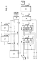
- the device for measuring the speed and slippage of the wheels of a vehicle comprises a logic processing circuit 1 connected on the one hand to a display module 2 and on the other hand to a a number of transducers providing it with information relating to the speed of the vehicle wheels, the ambient air temperature and the speed of the vehicle relative to the ground in the form of a Doppler signal.
- the Doppler signal is obtained by multiplication in a detection circuit 3 of the ultrasonic frequency signals emitted towards the ground by a transmitter 4 and received after reflection by a receiver 5.
- the transmitter 4 is powered from an oscillator of the processing 1, the signal of which is amplified by an amplifier 6 while the output signal of the receiver 5 is amplified by an amplifier 7 before application to the detection circuit 3, which moreover also receives the signal emitted by the oscillator.
- the Doppler signal generated by the detection circuit 3 is applied to the logic processing circuit 1 after filtering at 8.
- the detection circuit 3 is preferably constituted by an analog multiplier XR 2208 preceded by a Zener diode clipper making it possible to overcome the numerous variations in amplitude which the subjected ultrasonic signal undergoes and to attack the analog multiplier with signals constant amplitude to operate it as a phase detector.
- the detection circuit 3 therefore produces a signal containing the Doppler signal and the harmonics of the carrier, since the multiplier has produced the product of two sinusoidal functions slightly shifted in frequency.
- Circuit 8 is a bandpass filter whose bandwidth is chosen so as not to alter the Doppler signal while ensuring good rejection of the carrier and very low frequencies which could appear as a result of mechanical vibrations.
- the information relating to the speed of the wheels is supplied to circuit 1 by a sensor 9 arranged, for example, at the output of the vehicle gearbox and whose output signal is shaped into 10.
- circuit 1 the information relating to the ambient air temperature is supplied to circuit 1 by a thermistor or other suitable temperature sensor 11 and a shaping circuit 12.
- the logic processing circuit 1 is shown in more detail in FIG. 2 and includes a microprocessor 13, a read-only memory 14 containing the operating program of the microprocessor 13, a random access memory 15 for storing intermediate results, two timing circuits 16 and 17 ensuring the measurement of the speed of the wheels and of advancement relative to the ground of the vehicle, an analog-to-digital converter 18 for reading the temperature coming from the sensor 11, an output port 19 which controls the display module 2 and a decoder 20 which ensures the validation of circuits 14, 15, 16, 17, 18 and 19 by their input CS.
- the microprocessor 13 is connected by a data bus 21 to the circuits 14, 15, 16, 17, 18 and 19 and by an address bus 22 to the memories 14 and 15 and to the decoder 20.
- the timing circuits 16 and 17 are of the programmable type and interrupt the operation of the microprocessor 13 by its IRQ input to allow it to read their content and process this information.
- the timing circuit 16 comprises three counters 161, 162 and 163 programmed respectively as monostable, frequency comparator and oscillator.
- the counter 163 generates a frequency of, for example 36 kHz, which is applied to the amplifier 6, to the detection circuit 3, as well as to the clock inputs CK1 and CK2 of the counters 161 and 162 respectively.
- the Doppler signal from filter 8 is applied, via a Schmitt flip-flop 23 ensuring a final shaping, to the "gate" inputs G1 and G2 of the counters 161 and 162 respectively.
- the counter 162 generates an IRQ interrupt at each falling edge on its input G2, which causes its content to be read.
- the value read is then representative of the period of the Doppler signal: this counter 162 therefore provides a period measurement.
- the counter 161 programmed as monostable is reset on each falling edge on its G1 input: it thus sends an IRQ interrupt which causes the display to be reset to zero each time the Doppler frequency remains below a value given, for example 1 Hz.
- the timing circuit 17 also includes three counters 171, 172 and 173 which are used for measuring the slip.
- the timing circuit 17 makes it possible to measure the slip by applying the expression (1), it being understood that the numerical values given above should only be considered as an example in no way limiting the scope of the invention.
- the microprocessor 13 which has read the Doppler period measured by the timing circuit 16, controls the counter 173 so that it generates a frequency 2fd equal to the Doppler frequency multiplied by two and filtered.
- the counter 171 receives at its clock input CK1 the wheel speed signal fr from the sensor 9 and divides it by 35.
- the signal fr / 35 thus obtained is applied by the counter 171 to the "gate" input G2 of the counter 172 which receives on its clock input CK2 the signal 2fd of double frequency of the Doppler signal.
- the counter 172 which is programmed as a frequency comparator, sends the microprocessor 13 an IRQ interrupt which causes its content to be read, the value of which is equal to:
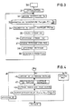
- step 30 the start of the main program (step 30) is followed by a step 31 for initializing the registers, random access memories, variables, ports, etc., by a step 32 for reading the temperature, d a step 33 for temperature correction, a step 34 for recreating the filtered Doppler signal, a step 35 for calculating the speed Vd of advancement of the vehicle, a step 36 for displaying the speed Vd advancement of the vehicle, a step 37 for calculating the slip, a step 38 for displaying the slip value and a step 39 for waiting for interruption.
- step 39 of the main program to branch B2 of the interruption program which constitutes an important phase of the implementation of the method according to the invention.
- This branch in fact ensures the processing of the Doppler signal which, at the end of the bandpass filter 8, cannot be used directly for the reasons mentioned above.
- the Doppler signal has an amplitude modulation which causes the loss of the signal for a certain time.
- the signal is formatted, it is necessary to set a threshold of detection, so as not to be sensitive to vehicle vibrations.
- the measurement device must therefore be capable of rejecting the erroneous information encountered by the period measurement.
- the frequency collected is not fixed either, it is necessary to filter the Doppler period measurement carried out. The distribution of this frequency depends directly on the radiation pattern of the ultrasonic cell, the opening angle of the directional horns must be chosen appropriately.
- the frequency modulation as well as the amplitude modulation of the Doppler signal therefore means that the period measurement carried out must pass through a certain number of filters.
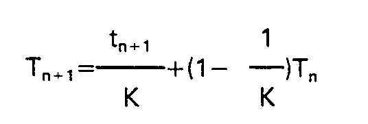
- step 40 After reading the Doppler period in the counter 162 (step 40) and resetting the latter (step 41), a median filtering on three values is performed in step 42 which results in l elimination of the two extreme values from a series of three values taken consecutively over time.
- the calculated value is relatively stable and the delay between the real speed and the measured speed for a step around 10 km / h is less than one second.
- step 34 a double frequency signal of the filtered and temperature-corrected Doppler signal is recreated by controlling the timing circuit 17 as indicated above.
- the actual speed of advance of the vehicle relative to the ground is then calculated in step 35. Knowing that the Doppler frequency and or
- step 36 The calculated speed of the vehicle Vd is then displayed (step 36), then the slip is calculated in the next step.
- the main program then remains in the waiting phase until the appearance of a new IRQ interrupt which initializes the progress of the interrupt program according to one of the branches B1, B2 or B3.
- the slip is not calculated by program in order not to increase the calculation time: the programmable timing circuit 17 is controlled by the microprocessor 13 to recreate a double frequency filtered Doppler frequency and then ensures a comparison between the actual vehicle speed and the wheel speed. In this way, the actual speed and slip information is as close as possible to reality during the transient states.
- this calculation can be performed directly by program in the microprocessor without departing from the scope of the invention.
Landscapes
- Engineering & Computer Science (AREA)
- Physics & Mathematics (AREA)
- Radar, Positioning & Navigation (AREA)
- Remote Sensing (AREA)
- Computer Networks & Wireless Communication (AREA)
- General Physics & Mathematics (AREA)
- Acoustics & Sound (AREA)
- Measurement Of Velocity Or Position Using Acoustic Or Ultrasonic Waves (AREA)
Claims (7)


Applications Claiming Priority (2)
| Application Number | Priority Date | Filing Date | Title |
|---|---|---|---|
| FR8317731A FR2554599B1 (fr) | 1983-11-08 | 1983-11-08 | Procede et dispositif de mesure par ultrasons de la vitesse d'avancement d'un vehicule par rapport au sol |
| FR8317731 | 1983-11-08 |
Publications (2)
| Publication Number | Publication Date |
|---|---|
| EP0146432A1 EP0146432A1 (de) | 1985-06-26 |
| EP0146432B1 true EP0146432B1 (de) | 1990-09-12 |
Family
ID=9293887
Family Applications (1)
| Application Number | Title | Priority Date | Filing Date |
|---|---|---|---|
| EP19840402234 Expired - Lifetime EP0146432B1 (de) | 1983-11-08 | 1984-11-07 | Verfahren und Vorrichtung zur Ultraschallmessung einer Fahrzeuggeschwindigkeit gegenüber dem Boden |
Country Status (4)
| Country | Link |
|---|---|
| EP (1) | EP0146432B1 (de) |
| DE (1) | DE3483202D1 (de) |
| ES (1) | ES537445A0 (de) |
| FR (1) | FR2554599B1 (de) |
Families Citing this family (1)
| Publication number | Priority date | Publication date | Assignee | Title |
|---|---|---|---|---|
| US4942558A (en) * | 1988-03-31 | 1990-07-17 | Micro-Trak Systems, Inc. | Ultrasonic velocity sensor |
Family Cites Families (7)
| Publication number | Priority date | Publication date | Assignee | Title |
|---|---|---|---|---|
| FR1273530A (fr) * | 1960-11-03 | 1961-10-13 | Bosch Arma Corp | Dispositif de mesure de la vitesse d'un véhicule terrestre par rapport au sol |
| DE1291545B (de) * | 1962-10-23 | 1969-03-27 | Telefunken Patent | Vorrichtung zum Ermitteln der Geschwindigkeit eines Fahrzeuges |
| US3915508A (en) * | 1973-10-15 | 1975-10-28 | Citroen Sa | Anti-locking systems for vehicle brakes |
| CH601804A5 (de) * | 1975-11-24 | 1978-07-14 | Patelhold Patentverwertung | |
| IT1074163B (it) * | 1976-06-11 | 1985-04-17 | Magneti Marelli Spa | Dispositivo per misurare la velocita di un veicolo particolarmente di un veicolo a trazione totale |
| DE2938764A1 (de) * | 1978-09-26 | 1980-04-10 | Hitachi Ltd | Montageaufbau und schlitzstrahlersystem fuer radargeraete zum erfassen der geschwindigkeit von damit ausgeruesteten kraftfahrzeugen |
| DE3017480A1 (de) * | 1980-05-07 | 1981-11-26 | Moto Meter Ag, 7250 Leonberg | Vorrichtung zur geschwindigkeitsmessung von fahrzeugen, insbesondere strassenfahrzeugen |
-
1983
- 1983-11-08 FR FR8317731A patent/FR2554599B1/fr not_active Expired
-
1984
- 1984-11-07 ES ES537445A patent/ES537445A0/es active Granted
- 1984-11-07 EP EP19840402234 patent/EP0146432B1/de not_active Expired - Lifetime
- 1984-11-07 DE DE8484402234T patent/DE3483202D1/de not_active Expired - Lifetime
Also Published As
| Publication number | Publication date |
|---|---|
| ES8601490A1 (es) | 1985-10-16 |
| EP0146432A1 (de) | 1985-06-26 |
| FR2554599B1 (fr) | 1987-07-31 |
| DE3483202D1 (de) | 1990-10-18 |
| ES537445A0 (es) | 1985-10-16 |
| FR2554599A1 (fr) | 1985-05-10 |
Similar Documents
| Publication | Publication Date | Title |
|---|---|---|
| EP0261736B1 (de) | Vorrichtung zur Untersuchung von ortsveränderlichen Medien mittels Ultraschall-Echographie | |
| FR2844748A1 (fr) | Systeme de controle de la pression des pneumatiques des roues d'un vehicule automobile | |
| FR2628216A1 (fr) | Anemometre ultrasonore | |
| FR2461257A1 (fr) | Dispositif de production de signal de vitesse de roue pour systeme de controle d'antipatinage | |
| EP0156084B1 (de) | Abstandsmessungsverfahren mit elektromagnetischen Wellen, angepasst bei Fortpflantzungsmediumsstörungen und nach diesem Verfahren arbeitender Entfernungsmesser | |
| EP3305186B1 (de) | Verfahren und system zur stressüberwachung eines benutzers | |
| EP0703468B1 (de) | Verfahren und Vorrichtung zum Bestimmen von anemometrischen, barometrischen und Neigungs-Parametern für Luftfahrzeuge | |
| EP0080417A1 (de) | Verfahren und Vorrichtung zur Aufzeichnung von Fötalbewegungen während der Schwangerschaft | |
| EP1465782B1 (de) | System zur steuerung des reifendrucks eines fahrzeugrads | |
| WO2009103769A1 (fr) | Procede d'interrogation de resonateur piezoelectrique et dispositif d'interrogation integrant le procede d'interrogation | |
| EP0146432B1 (de) | Verfahren und Vorrichtung zur Ultraschallmessung einer Fahrzeuggeschwindigkeit gegenüber dem Boden | |
| EP0596342A1 (de) | Ultraschallmessgerät mit Minimierung der Zahl der durch die Verarbeitungsmitteln verarbeiteten digitalen Daten | |
| FR2602048A1 (fr) | Dispositif pour evaluer la deformation des pneumatiques de vehicules | |
| EP0094298B1 (de) | Verfahren und Vorrichtung zur Flüssigkeitsniveaumessung in einem Fahrzeugtank | |
| EP0665505B1 (de) | Verfahren und Vorrichtung zur Erfassung eines physikalischen Parameters | |
| EP0027411B1 (de) | Verfahren zur Leistungsmessung eines Kraftfahrzeugmotors mittels eines Rollenprüfstandes und Prüfstand zur Durchführung dieses Verfahrens | |
| EP1442306A2 (de) | Verfahren und system zur messung der drehzahl von kraftfahrzeugrädern | |
| FR2829427A1 (fr) | Procede et systeme de detection d'un changement d'etat d'un pneumatique | |
| WO2008155252A1 (fr) | Procédé et dispositif de détermination de l' angle de relèvement dans un système de radionavigation de type tacan | |
| EP4001859B1 (de) | Verfahren zur verarbeitung eines messsignals zur erstellung einer signatur, und entsprechende messvorrichtung | |
| EP0900390A1 (de) | Verfahren, vorrichtung und gerät zum messen des abstands zwischen einem gegenstand und einem gerät | |
| FR2512860A1 (fr) | Dispositif de commande de surface de type numerique pour essais de sols et de roches in situ avec sonde profonde | |
| WO2019063566A1 (fr) | Procédé de détermination de la fréquence et de la phase instantanées d'un signal périodique | |
| CH685420A5 (fr) | Procédé de mesure par ultrasons de la position d'au moins une paroi mobile et appareil pour la mise en oeuvre de ce procédé. | |
| EP3781952A1 (de) | Ultraschallanemometer |
Legal Events
| Date | Code | Title | Description |
|---|---|---|---|
| PUAI | Public reference made under article 153(3) epc to a published international application that has entered the european phase |
Free format text: ORIGINAL CODE: 0009012 |
|
| 17P | Request for examination filed |
Effective date: 19841110 |
|
| AK | Designated contracting states |
Designated state(s): DE GB IT NL |
|
| 17Q | First examination report despatched |
Effective date: 19870819 |
|
| GRAA | (expected) grant |
Free format text: ORIGINAL CODE: 0009210 |
|
| PGFP | Annual fee paid to national office [announced via postgrant information from national office to epo] |
Ref country code: GB Payment date: 19900903 Year of fee payment: 7 |
|
| PGFP | Annual fee paid to national office [announced via postgrant information from national office to epo] |
Ref country code: DE Payment date: 19900907 Year of fee payment: 7 |
|
| AK | Designated contracting states |
Kind code of ref document: B1 Designated state(s): DE GB IT NL |
|
| ITF | It: translation for a ep patent filed | ||
| REF | Corresponds to: |
Ref document number: 3483202 Country of ref document: DE Date of ref document: 19901018 |
|
| ITTA | It: last paid annual fee | ||
| PGFP | Annual fee paid to national office [announced via postgrant information from national office to epo] |
Ref country code: NL Payment date: 19901130 Year of fee payment: 7 |
|
| GBT | Gb: translation of ep patent filed (gb section 77(6)(a)/1977) | ||
| PLBE | No opposition filed within time limit |
Free format text: ORIGINAL CODE: 0009261 |
|
| STAA | Information on the status of an ep patent application or granted ep patent |
Free format text: STATUS: NO OPPOSITION FILED WITHIN TIME LIMIT |
|
| 26N | No opposition filed | ||
| PG25 | Lapsed in a contracting state [announced via postgrant information from national office to epo] |
Ref country code: GB Effective date: 19911107 |
|
| PG25 | Lapsed in a contracting state [announced via postgrant information from national office to epo] |
Ref country code: NL Effective date: 19920601 |
|
| GBPC | Gb: european patent ceased through non-payment of renewal fee | ||
| NLV4 | Nl: lapsed or anulled due to non-payment of the annual fee | ||
| PG25 | Lapsed in a contracting state [announced via postgrant information from national office to epo] |
Ref country code: DE Effective date: 19920801 |