EP4001859B1 - Verfahren zur verarbeitung eines messsignals zur erstellung einer signatur, und entsprechende messvorrichtung - Google Patents
Verfahren zur verarbeitung eines messsignals zur erstellung einer signatur, und entsprechende messvorrichtung Download PDFInfo
- Publication number
- EP4001859B1 EP4001859B1 EP21209189.6A EP21209189A EP4001859B1 EP 4001859 B1 EP4001859 B1 EP 4001859B1 EP 21209189 A EP21209189 A EP 21209189A EP 4001859 B1 EP4001859 B1 EP 4001859B1
- Authority
- EP
- European Patent Office
- Prior art keywords
- signal
- measurement
- processing
- measurement signal
- reduced
- Prior art date
- Legal status (The legal status is an assumption and is not a legal conclusion. Google has not performed a legal analysis and makes no representation as to the accuracy of the status listed.)
- Active
Links
Images




Classifications
-
- G—PHYSICS
- G01—MEASURING; TESTING
- G01F—MEASURING VOLUME, VOLUME FLOW, MASS FLOW OR LIQUID LEVEL; METERING BY VOLUME
- G01F23/00—Indicating or measuring liquid level or level of fluent solid material, e.g. indicating in terms of volume or indicating by means of an alarm
- G01F23/22—Indicating or measuring liquid level or level of fluent solid material, e.g. indicating in terms of volume or indicating by means of an alarm by measuring physical variables, other than linear dimensions, pressure or weight, dependent on the level to be measured, e.g. by difference of heat transfer of steam or water
- G01F23/28—Indicating or measuring liquid level or level of fluent solid material, e.g. indicating in terms of volume or indicating by means of an alarm by measuring physical variables, other than linear dimensions, pressure or weight, dependent on the level to be measured, e.g. by difference of heat transfer of steam or water by measuring the variations of parameters of electromagnetic or acoustic waves applied directly to the liquid or fluent solid material
- G01F23/296—Acoustic waves
- G01F23/2962—Measuring transit time of reflected waves
-
- G—PHYSICS
- G01—MEASURING; TESTING
- G01F—MEASURING VOLUME, VOLUME FLOW, MASS FLOW OR LIQUID LEVEL; METERING BY VOLUME
- G01F23/00—Indicating or measuring liquid level or level of fluent solid material, e.g. indicating in terms of volume or indicating by means of an alarm
- G01F23/14—Indicating or measuring liquid level or level of fluent solid material, e.g. indicating in terms of volume or indicating by means of an alarm by measurement of pressure
-
- G—PHYSICS
- G01—MEASURING; TESTING
- G01F—MEASURING VOLUME, VOLUME FLOW, MASS FLOW OR LIQUID LEVEL; METERING BY VOLUME
- G01F23/00—Indicating or measuring liquid level or level of fluent solid material, e.g. indicating in terms of volume or indicating by means of an alarm
- G01F23/14—Indicating or measuring liquid level or level of fluent solid material, e.g. indicating in terms of volume or indicating by means of an alarm by measurement of pressure
- G01F23/18—Indicating, recording or alarm devices actuated electrically
-
- G—PHYSICS
- G01—MEASURING; TESTING
- G01F—MEASURING VOLUME, VOLUME FLOW, MASS FLOW OR LIQUID LEVEL; METERING BY VOLUME
- G01F23/00—Indicating or measuring liquid level or level of fluent solid material, e.g. indicating in terms of volume or indicating by means of an alarm
- G01F23/22—Indicating or measuring liquid level or level of fluent solid material, e.g. indicating in terms of volume or indicating by means of an alarm by measuring physical variables, other than linear dimensions, pressure or weight, dependent on the level to be measured, e.g. by difference of heat transfer of steam or water
- G01F23/26—Indicating or measuring liquid level or level of fluent solid material, e.g. indicating in terms of volume or indicating by means of an alarm by measuring physical variables, other than linear dimensions, pressure or weight, dependent on the level to be measured, e.g. by difference of heat transfer of steam or water by measuring variations of capacity or inductance of capacitors or inductors arising from the presence of liquid or fluent solid material in the electric or electromagnetic fields
- G01F23/263—Indicating or measuring liquid level or level of fluent solid material, e.g. indicating in terms of volume or indicating by means of an alarm by measuring physical variables, other than linear dimensions, pressure or weight, dependent on the level to be measured, e.g. by difference of heat transfer of steam or water by measuring variations of capacity or inductance of capacitors or inductors arising from the presence of liquid or fluent solid material in the electric or electromagnetic fields by measuring variations in capacitance of capacitors
- G01F23/265—Indicating or measuring liquid level or level of fluent solid material, e.g. indicating in terms of volume or indicating by means of an alarm by measuring physical variables, other than linear dimensions, pressure or weight, dependent on the level to be measured, e.g. by difference of heat transfer of steam or water by measuring variations of capacity or inductance of capacitors or inductors arising from the presence of liquid or fluent solid material in the electric or electromagnetic fields by measuring variations in capacitance of capacitors for discrete levels
-
- G—PHYSICS
- G01—MEASURING; TESTING
- G01F—MEASURING VOLUME, VOLUME FLOW, MASS FLOW OR LIQUID LEVEL; METERING BY VOLUME
- G01F23/00—Indicating or measuring liquid level or level of fluent solid material, e.g. indicating in terms of volume or indicating by means of an alarm
- G01F23/22—Indicating or measuring liquid level or level of fluent solid material, e.g. indicating in terms of volume or indicating by means of an alarm by measuring physical variables, other than linear dimensions, pressure or weight, dependent on the level to be measured, e.g. by difference of heat transfer of steam or water
- G01F23/28—Indicating or measuring liquid level or level of fluent solid material, e.g. indicating in terms of volume or indicating by means of an alarm by measuring physical variables, other than linear dimensions, pressure or weight, dependent on the level to be measured, e.g. by difference of heat transfer of steam or water by measuring the variations of parameters of electromagnetic or acoustic waves applied directly to the liquid or fluent solid material
- G01F23/284—Electromagnetic waves
-
- G—PHYSICS
- G01—MEASURING; TESTING
- G01F—MEASURING VOLUME, VOLUME FLOW, MASS FLOW OR LIQUID LEVEL; METERING BY VOLUME
- G01F23/00—Indicating or measuring liquid level or level of fluent solid material, e.g. indicating in terms of volume or indicating by means of an alarm
- G01F23/80—Arrangements for signal processing
-
- G—PHYSICS
- G01—MEASURING; TESTING
- G01F—MEASURING VOLUME, VOLUME FLOW, MASS FLOW OR LIQUID LEVEL; METERING BY VOLUME
- G01F23/00—Indicating or measuring liquid level or level of fluent solid material, e.g. indicating in terms of volume or indicating by means of an alarm
- G01F23/80—Arrangements for signal processing
- G01F23/806—Particular electronic circuits for handling non-digital processing equipment
- G01F23/808—Particular electronic circuits for handling non-digital processing equipment containing circuits handling parameters other than liquid level
-
- G—PHYSICS
- G05—CONTROLLING; REGULATING
- G05B—CONTROL OR REGULATING SYSTEMS IN GENERAL; FUNCTIONAL ELEMENTS OF SUCH SYSTEMS; MONITORING OR TESTING ARRANGEMENTS FOR SUCH SYSTEMS OR ELEMENTS
- G05B23/00—Testing or monitoring of control systems or parts thereof
- G05B23/02—Electric testing or monitoring
- G05B23/0205—Electric testing or monitoring by means of a monitoring system capable of detecting and responding to faults
- G05B23/0259—Electric testing or monitoring by means of a monitoring system capable of detecting and responding to faults characterized by the response to fault detection
- G05B23/0264—Control of logging system, e.g. decision on which data to store; time-stamping measurements
Definitions
- the present invention relates to a method for processing a measurement signal of a physical quantity and a device for measuring a physical quantity implementing said method.
- Instrumentation devices are known from the prior art which deliver a final measurement, possibly with an indication of the performance of the measurement carried out.
- the present invention aims to overcome these drawbacks with a completely innovative approach.
- the invention aims to provide a technique for storing data whose acquisition history is available to a user, to provide information on the quality of the final measurement signal, and to provide a detailed signal allowing an interpretation of the raw measurement signal while keeping a significant amount of information with respect to this raw measurement signal.
- an objective of the invention is to provide such a technique for quickly identifying anomalies at the sensor site, and for carrying out remedial operations for these anomalies, such as cleaning, calibration, replacement, etc.
- Another objective of the invention is to judge the relevance of a measurement site, by highlighting the presence or absence of the physical phenomena to be measured. It is thus possible to provide measurements representative of the metrological system, and makes it possible to avoid unnecessary instrumentation.
- This time stamping has the advantage of making it possible to associate a measurement carried out at a given time with an event occurring at that given time, and thus in particular to allow an evaluation of the validity of the measurement point.
- the storage step may comprise the storage of the first reduced signal, with or without the storage of the measurement signal. It is also possible to store only the storage of the measurement signal alone.
- this process is not systematically implemented throughout the duration of the measurement (which may be continuous in certain cases), and may be triggered by specific events, according to predefined criteria.
- the measurement signal can also be a video frame composed of several images, or simply one or more images.
- This type of measurement signal can be representative of a physical quantity in a large number of cases, such as for example a visually identifiable liquid level, the obstruction of a pipe, the rupture of an element, etc.
- the first reduced signal may be an image or a video.
- the graph of a value of the measured signal over time may itself be a reduced signal, i.e. an image of the graph is produced and stored as the first (or second) reduced signal.
- a temperature field represented as a heat map is a reduced signal in the form of an image, coming from multiple temperature probes (or from a single moving probe).
- the step of processing the measurement signal is a step of processing Fourier series, and/or of detecting peaks in the measurement signal.
- the step of processing the measurement signal is a step of temporal statistical analysis of the measurement signal.
- the calculation of one or more quality indicators is chosen from a signal-to-noise ratio, a saturation percentage, a quality of a speed signal.
- a final measurement signal is obtained, this second reduced signal being generally used in normal circumstances (in particular to control systems according to measurement signals), the first reduced signal, representing a digital signature of the raw measurement, being used in case of need for interpretation, verification, validation, etc. of the final measurement.
- the second reduced signal is a scalar value.
- the digital filtering is adapted to each type of measurement chosen from a bandpass and an integrator.
- the techniques used are chosen from linear interpolation, Chebyshev filters, Butterworth and a Hilbert transform.
- the second reduced signal is a scalar value representative of the physical quantity (for example the flow speed in a channel is represented by the average speed, the first reduced signal being a distribution of the speeds measured by Doppler effect, making it possible to observe a normal (i.e. Gaussian) distribution of the speeds of the particles (air bubbles, impurities) measured in the fluid).
- the present invention aims at a device for measuring a physical quantity useful for implementing a method which is the subject of the present invention, comprising a signal processing unit comprising a clock, a sensor and a non-volatile means for storing information connected to said processing unit.
- the sensor is selected from the groups of piezoelectric, ultrasonic and radar sensors, which may be with or without Doppler effect.
- FIG. 1 represents a block diagram of a method 100 for processing a measurement signal of a physical quantity according to the invention.
- the method 100 which will be described in more detail below is implemented by a measuring device 200 described below.
- FIG. 2 represents the measuring device 200 comprising a sensor (or probe) 210 connected to a signal processing unit 220, comprising a clock 221.
- the signal processing unit 220a and the sensor 210 are arranged in the same housing 230.
- the signal processing unit 220b is located remotely from the sensor 210, and a remote communication module 240 located near the sensor 210 and connected to the latter allows communication with the signal processing unit 220b.
- the processing unit comprises a microcontroller which makes it possible to carry out the signal processing.
- the microcontroller is connected to the various elements to control or make step calculations of the method described.
- the processing unit comprises a battery enabling the calculations of the process to be carried out locally.
- the measuring device 200 comprises a database 250, which can be either located in proximity to the sensor 210, or in proximity to the signal processing unit 220b remote from the sensor 210, or remote from the sensor 210 and the signal processing unit 220b in a third location.
- the database 250 is generally a non-volatile information storage memory connected to the signal processing unit, and can also take the form of a remote data storage server, in the third case referred to above.
- figures 2 And 3 each show a variant with a 250 database located in a third party location.
- the measuring device 200 is suitable for operating with piezoelectric sensors, ultrasonic sensors, capacitive sensors, radar sensors, and in particular Doppler radar sensors.
- a measurement signal is acquired by means of the sensor 210 connected to the signal processing unit 220, the measurement signal being representative of a value of the physical quantity measured.
- the method 100 is suitable for any type of sensor, and in particular piezoelectric sensors, ultrasonic sensors, capacitive sensors, radar sensors, and in particular Doppler radar sensors.
- the reception of the echo of a wave by an ultrasonic sensor is representative of the distance of the obstacle having returned said echo, knowing the time of emission of the wave.
- the variation in the electric capacitance of the electric field between the two electrodes of a capacitive sensor is representative of the type of body passing between the electrodes (in particular water), by deducing its nature using its measured dielectric constant.
- An application of such an example can be found in monitoring a presence of liquid near the sensor, allowing to monitor a liquid level overflow.
- the frequency spectrum of a Doppler radar signal is representative of the relative speed between an object and the Doppler radar.
- the electric current generated by the deformation of a piezoelectric sensor is representative of the pressure exerted on the sensor, and/or the vibrations experienced by the sensor.
- MEMS microelectromechanical systems
- the measurement signal is processed by the signal processing unit 220.
- This processing corresponds to a creation of said digital signature and its various sub-steps.
- This digital signature is certainly a reduction of the raw signal by the sampling technique but represents above all an enrichment of the signal by the application of digital filters.
- Calculations of quality indicators adapted to the process also represent an enrichment of the signal.
- the present method can also omit the second step 102, and not produce a first reduced signal at this stage of the method.
- the goal of this processing is to obtain a signal that is more easily interpretable than the raw measurement signal, while retaining enough information to keep a detailed history allowing an even smaller final measurement signal to be interpreted.
- this first digital signature is useful for a user seeking to understand the origin of an anomaly, to check the behavior of the sensor, to calibrate/calibrate the sensor, to perform maintenance operations, etc.
- the signal processing is a Fourier series processing, and/or a peak detection in the measurement signal. It is thus possible to obtain a simplified acoustic echo, in which the peaks of the acoustic wave are quickly identifiable.
- the signal processing is a calculation of the capacitive saturation of the sensor from the capacitive value of a first antenna called the reference antenna and the capacitive value of a second antenna called the measurement antenna.
- This type of measurement is particularly useful for detecting the presence of water near the sensor.
- the signal processing is a Doppler signature, statistically calculated from the multiple Doppler measurements.
- the processing is a temporal statistical analysis of the measurements.
- this first reduced signal is generally not a final measurement signal allowing direct interpretation by an individual or a machine, but allows a more detailed reading of the final measurement signal.
- the first reduced signal is not systematically a scalar value, but can also include continuous signals and/or series of values.
- the measurement signal is stored in the database 250.
- This stored signal is generally the digital signature obtained at the end of the second step 102.
- the stored signal is the raw measurement signal.
- the signal is stored with time information, that is, each measurement point of the stored signal is associated with a date.
- each measurement point is time-stamped, so as to obtain the history of the measurement carried out.
- variants of this embodiment provide for storing a quality level indicator of the stored signal.
- This quality level is determined by the signal processing unit 220 as a function of characteristics of the measurement signal.
- “Characteristics of the measurement signal” means intrinsic data of the signal, but also data relating to the conditions of acquisition of the signal, or possibly to the conditions of calculation of the signal.
- the indicator is for example an integer between 1 and 4, defining four levels of quality, from the poorest to the highest.
- quality level "1" would correspond to a value entered by the user instead of a measured value (in the event of a faulty sensor for example)
- level "2" would correspond to a final value estimated from the measured signal
- level "3” would correspond to a value calculated from the measured signal (for example an average speed calculated using predetermined coefficients multiplied by a maximum measured speed), corresponding to satisfactory quality, in accordance with the requirements of the field of application
- level "4" would correspond to a directly measured value (such as an average speed directly from the measured speeds), corresponding to higher quality, the measured value being determined under optimal conditions.
- the first reduced signal is processed by the signal processing unit 220.
- This processing corresponds to a reduction of the information contained in the first reduced signal, so as to obtain a second reduced signal.
- the second reduced signal also corresponds to the final measured value, which is used by the user or a machine.
- the second reduced signal is a scalar value, for example in the case of measurements of speeds, distances, pressures, etc.
- the method 100 does not include step 102, it is the raw measurement signal which is reduced during the fourth step 104, so as to obtain a single reduced signal.
- the measurement signal is either reduced to a first reduced signal and stored directly in the database 250, or stored directly in the database 250, being associated with time information making it possible to constitute a measurement history.
- a second (or first, depending on the cases referred to above) processing of the signal a second (or first, depending on the cases referred to above) reduced signal is obtained, which generally corresponds to a final measurement signal, used by a machine or a user.
- the first application case concerns an urban sanitation system.
- this example concerns the self-monitoring of storm overflows.
- FIG 4 illustrates such a storm overflow 400 instrumented with an ultrasonic sensor 401 for measuring the water height (which can be substituted by radar sensors) and a capacitive sensor 402 for measuring the overflow of the overflow (presence or absence of liquid at a given level), being advantageously connected wirelessly to a central processing unit 403, and energy autonomous.
- an ultrasonic sensor 401 for measuring the water height (which can be substituted by radar sensors)
- a capacitive sensor 402 for measuring the overflow of the overflow (presence or absence of liquid at a given level)
- the central processing unit comprises a wireless communication module.
- a communication module may be a module of the “GSM” ( Global System for Mobile Communications ), UMTS ( Universal Mobile Telecommunications System ), LTE ( Long Term Evolution ) or or 5G, or any standard, so as to transmit data, in particular by SMS ( Short Message Service ) type messages or data via the Internet, to a user or a monitoring center.
- GSM Global System for Mobile Communications
- UMTS Universal Mobile Telecommunications System
- LTE Long Term Evolution
- 5G Fifth Generation
- SMS Short Message Service
- LPWAN low-power wide area network
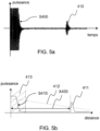
- a raw measurement signal S400 is acquired, corresponding to the power (in watts or equivalent) of the echo of the ultrasonic shots over time, as can be seen on the graph of the Figure 5a .
- a peak 401 is visible on this graph, which corresponds to an echo returned by an obstacle.
- This raw measurement signal S400 is processed in order to obtain the envelope graph of the signal S400, but over distance and no longer time, by using the propagation speed of ultrasonic waves, which is known.
- This first reduced measurement signal S410 is shown in Figure 5b .
- a peak 411 corresponding to peak 401 is visible, but in a spatial dimension and no longer temporal.
- This first reduced measurement signal S410 is also completed by characteristic values of said signal or associated with the measurement, such as the front of peak 411, corresponding to the distance X400 of the obstacle relative to the sensor, the decrement of the power of the shot in space 412, the measurement exclusion zone 413 (echoes too close to the sensor), the measurement temperature, or any other value associated with the measurement.
- the first reduced measurement signal 410 is processed so as to obtain a second reduced measurement signal S420, intended to be communicated to a user or to the monitoring center.
- this second reduced signal S420 is a scalar value corresponding to the distance of the sensor relative to the surface of the water in the spillway.
- the second reduced signal S420 which is the final measurement signal, corresponds to the value X400 in this example.
- the final measurement signal S420 is the signal used for system supervision
- the first reduced measurement signal S410 is recorded and stored in a non-volatile storage memory in order to allow a posteriori consultation, in order to interpret a final measurement which would appear abnormal, for example.
- a raw measurement signal S500 is first acquired by the two capacitive detectors (antennas).
- the raw signal from each detector comparable to a capacitor, is an electrical capacitance value (in farads or equivalent) over time.
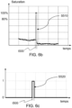
- the raw signal S500 is processed so as to obtain a first reduced measurement signal S510, which is a capacitive saturation expressed as a percentage over time.
- the associated processing corresponds to a self-adaptation over a range of minimum and maximum values of the measured capacitances.
- the S510 signal takes a high capacitive saturation value when the reference antenna and the measurement antenna have a large capacitance difference.
- the capacitive saturation value is greater than a determined threshold, which indicates the presence of water at the measurement antenna.
- a threshold is preferably of the order of 80%.
- the first reduced signal S510 is processed so as to obtain a second reduced signal S520, which is here a value that can take two different values over time, in particular 0 and 1 (Boolean type variable), so as to indicate the presence or absence of an overflow.
- the second reduced measurement signal S520 represented in figure 6c , takes the value 1 over the time range t500, where the presence of water is detected, and 0 the rest of the time.
- the first reduced signal S510 is stored so that it can be consulted later to interpret the values of the second reduced signal S520, if necessary.
- the second application case concerns an ultrasonic or piezoelectric Doppler sensor in a channel, a pipe, or similar.
- the sensor is immersed and located on the bottom of the channel or a wall of the pipe.
- the sensor emits ultrasound which is reflected by particles (e.g. impurities) and/or air bubbles carried by a fluid flowing in the channel or pipe.
- the movement of particles and/or air bubbles is at the origin of the phenomenon known as the "Doppler effect", which consists of a difference in frequency of the emitted wave and the wave received after reflection by a moving element. This effect makes it possible to deduce the speed of the moving element, and here of the fluid flowing in the channel or pipe.
- the average of the speeds of the moving elements is approximately equivalent to the average speed of the fluid.
- a raw measurement signal is in this case the power of the signal received over time, being the sum of the echoes returned by each moving element in the fluid.
- a first signal processing allows to obtain a first reduced signal.
- This second reduced signal is obtained for example by a Fourier series processing, allowing to obtain the amplitude and the phase difference for each frequency.
- FIG. 7 is an example of a representation of the quality level that can be associated with an average speed value, according to the criteria defined above.
- a second reduced signal S600 is obtained, and here corresponds to a scalar value V600 of average fluid velocity.
- the storage of the first reduced measurement signal, and of the quality indicator makes it possible to verify the relevance of the final measurement signal S640.
- the first reduced measurement signal makes it possible to verify the validity of the quality indicator, and therefore of the method for determining the final measurement signal S640.
- a quality indicator can be constructed and stored from the raw or semi-raw data of a third-party sensor, so as to provide added value compared to simple storage third-party sensor data, and allow easy interpretation, especially when the sensor uses non-standard or proprietary formats.
- the method which is the subject of the invention can be implemented partially, in cooperation with a third-party measuring device, by executing only the steps from which the sensor information is accessible (the steps of acquiring the signal and/or the first reduction of the signal can be carried out by a third-party method, independently and/or differently from the steps described in the present description).
- the method and device that are the subject of the present invention are generalizable to any type of sensor on any type of system, and that any type of signal processing can be applied to the raw measurement signal in order to obtain a digital signature and therefore a first reduced measurement signal, then to the first reduced measurement signal in order to obtain a second reduced measurement signal. It is also clear that any quality indicator can be constructed by the user of the present method and device, so as to correspond to his own needs.
Landscapes
- Physics & Mathematics (AREA)
- General Physics & Mathematics (AREA)
- Fluid Mechanics (AREA)
- Engineering & Computer Science (AREA)
- Electromagnetism (AREA)
- Thermal Sciences (AREA)
- Signal Processing (AREA)
- Power Engineering (AREA)
- Acoustics & Sound (AREA)
- Automation & Control Theory (AREA)
- Testing Or Calibration Of Command Recording Devices (AREA)
- Recording Measured Values (AREA)
- Electric Clocks (AREA)
- Measurement Of Levels Of Liquids Or Fluent Solid Materials (AREA)
Claims (9)
- Verfahren (100) zur Verarbeitung eines Meßsignals einer physikalischen Größe durch eine Signalverarbeitungseinheit (220) mit einer Uhr (221),
dadurch gekennzeichnet, daß es die folgenden Schritte aufweist:- Erfassen (101) des Meßsignals mittels eines mit der Signalverarbeitungsvorrichtung verbundenen Sensors (210), wobei das Meßsignal für einen gemessenen Wert der physikalischen Größe steht, wobei die Signalverarbeitungseinheit (220) eine Uhr (221), einen Sensor (210) und ein nicht flüchtiges Mittel (250) zum Speichern der Information aufweist, die mit der Verarbeitungseinheit verbunden sind;- Verarbeiten (102) des Meßsignals, wobei das Verarbeiten einer Reduzierung einer im Meßsignal enthaltenen Information entspricht, um ein erstes reduziertes Signal zu erhalten, wobei das erste reduzierte Signal eine digitale Signatur des Meßsignals darstellt, wobei das Verarbeiten (102) des Meßsignals zum Erhalten der digitalen Signatur die folgenden Unterschritte aufweist:- Abtasten des Bruttomeßsignals, das heißt eine Umwandlung eines oder mehrerer analoger Signale in ein oder mehrere digitale Signale;- digitale Verarbeitungsfilterung des im vorangehenden Schritt abgetasteten Signals, um die notwendigen Informationen zu behalten und eventuelle Geräusche zu unterdrücken;- Glätten der Ergebnisse der digitalen Filterung, um ein geglättetes Signal zu erhalten,- Auswählen mindestens einer Meßzone mit einer Meßausschlußzone (413), die durch Vergleich des geglätteten Signals des vorangehenden Schritts mit einem aus einer Datenbank stammenden Signal identifiziert wird;- Speichern (103) des durch die vorangehenden Unterschritte verarbeiteten ersten reduzierten Signals mit einer Zeitinformation in einer Datenbank (250) und einer Berechnung mindestens eines Indikators des Qualitätsniveaus des gespeicherten Signals, wobei das Niveau durch die Signalverarbeitungseinheit (220) in Abhängigkeit von den Merkmalen des Meßsignals bestimmt wird. - Verfahren (100) gemäß Anspruch 1, wobei der Schritt (102) des Verarbeitens des Meßsignals ein Schritt des Verarbeitens als Fourier-Reihe und/oder des Suchens von Spitzen im Meßsignal ist.
- Verfahren (100) gemäß Anspruch 1, wobei der Schritt (102) des Verarbeitens des Meßsignals ein Schritt der zeitlichen statistischen Analyse des Meßsignals ist.
- Verfahren (100) gemäß Anspruch 1, wobei das Berechnen eines oder der Qualitätsindikatoren aus einem Signal-Rausch-Verhältnis, einem Prozentsatz der Sättigung, einer Qualität eines Geschwindigkeitssignals ausgewählt wird.
- Verfahren (100) gemäß den Ansprüchen 1 bis 4, wobei das Verfahren nach dem Speicherschritt (103) außerdem den folgenden Schritt aufweist:- Verarbeiten (104) des ersten reduzierten Signals, wobei die Verarbeitung einer Reduzierung der in dem ersten reduzierten Signal enthaltenen Information entspricht, um ein zweites reduziertes Signal zu erhalten.
- Verfahren (100) gemäß Anspruch 5, wobei das zweite reduzierte Signal ein skalarer Wert ist.
- Verfahren (100) gemäß Anspruch 1, wobei die digitale Filterung beim Filterungsschritt an jeden Messungstyp, ausgewählt aus einem Bandpaß und einem Integrator, angepaßt wird.
- Verfahren (100) gemäß Anspruch 1, wobei die verwendeten Techniken beim Glättungsschritt aus einer linearen Interpolation, einem Tschebyscheff-Filter, einem Butterworth-Filter und einer Hilbert-Transformierten ausgewählt werden.
- Vorrichtung (200) zum Messen einer physikalischen Größe, die für die Durchführung eines Verfahrens (100) gemäß einem der Ansprüche 1 bis 8 dienlich ist, wobei der Sensor (210) aus den Gruppen der piezoelektrischen Sensoren, der Ultraschallsensoren und Radarsensoren, insbesondere der Dopplerradarsensoren, ausgewählt ist.
Applications Claiming Priority (1)
| Application Number | Priority Date | Filing Date | Title |
|---|---|---|---|
| FR2011876A FR3116336B1 (fr) | 2020-11-19 | 2020-11-19 | Procédé de traitement d’un signal de mesure pour obtenir une signature et dispositif de mesure associé |
Publications (3)
| Publication Number | Publication Date |
|---|---|
| EP4001859A1 EP4001859A1 (de) | 2022-05-25 |
| EP4001859B1 true EP4001859B1 (de) | 2024-10-09 |
| EP4001859C0 EP4001859C0 (de) | 2024-10-09 |
Family
ID=74347302
Family Applications (1)
| Application Number | Title | Priority Date | Filing Date |
|---|---|---|---|
| EP21209189.6A Active EP4001859B1 (de) | 2020-11-19 | 2021-11-19 | Verfahren zur verarbeitung eines messsignals zur erstellung einer signatur, und entsprechende messvorrichtung |
Country Status (2)
| Country | Link |
|---|---|
| EP (1) | EP4001859B1 (de) |
| FR (1) | FR3116336B1 (de) |
Families Citing this family (1)
| Publication number | Priority date | Publication date | Assignee | Title |
|---|---|---|---|---|
| FR3152589A1 (fr) * | 2023-08-28 | 2025-03-07 | greencityzen | Procede de mesure de niveaux d’effluents dans un reseau d’assainissement au moyen d’un capteur ultrasons connecte |
Family Cites Families (6)
| Publication number | Priority date | Publication date | Assignee | Title |
|---|---|---|---|---|
| US20110046659A1 (en) | 2007-07-09 | 2011-02-24 | Immersion Corporation | Minimally Invasive Surgical Tools With Haptic Feedback |
| US9625349B2 (en) * | 2012-02-29 | 2017-04-18 | Fisher Controls International Llc | Time-stamped emissions data collection for process control devices |
| FR3005357B1 (fr) * | 2013-05-06 | 2017-02-17 | Smart Impulse | Procede et systeme d'analyse de la consommation d'electricite |
| US10161782B2 (en) * | 2014-07-25 | 2018-12-25 | Trago, Inc. | Liquid consumption tracker |
| US11226615B2 (en) * | 2017-05-02 | 2022-01-18 | Lateral Solutions, Inc. | Control system for machine with a plurality of components and methods of operation |
| CN111052758A (zh) * | 2017-05-11 | 2020-04-21 | 尼科达公司 | 内容物的量的检测和分析 |
-
2020
- 2020-11-19 FR FR2011876A patent/FR3116336B1/fr active Active
-
2021
- 2021-11-19 EP EP21209189.6A patent/EP4001859B1/de active Active
Also Published As
| Publication number | Publication date |
|---|---|
| EP4001859A1 (de) | 2022-05-25 |
| FR3116336A1 (fr) | 2022-05-20 |
| FR3116336B1 (fr) | 2023-08-04 |
| EP4001859C0 (de) | 2024-10-09 |
Similar Documents
| Publication | Publication Date | Title |
|---|---|---|
| EP3209993B1 (de) | Verfahren und vorrichtung zur überwachung von einer flugzeugsturbineschaufel durch messung einer gleichgewichtposition | |
| FR2949352A1 (fr) | Surveillance d'un filtre servant au filtrage d'un fluide dans un moteur d'aeronef | |
| EP3892976B1 (de) | Verfahren zur erkennung und lokalisierung eines fluidlecks | |
| FR2673290A1 (fr) | Dispositif et procede pour detecter des particules ferreuses entrainees dans un fluide. | |
| EP3305186B1 (de) | Verfahren und system zur stressüberwachung eines benutzers | |
| EP4001859B1 (de) | Verfahren zur verarbeitung eines messsignals zur erstellung einer signatur, und entsprechende messvorrichtung | |
| FR3095271A1 (fr) | Système de surveillance de la santé d’un hélicoptère | |
| WO2019207243A1 (fr) | Procédé et système de contrôle non destructif d'une pièce mécanique | |
| FR3121212A1 (fr) | Procédé de prédiction du risque de gel d’un liquide | |
| FR3050277A1 (fr) | Systeme et procede de detection d'un arc electrique | |
| EP2146188A2 (de) | Verfahren zum Entdecken einer Störung an einem Analogsensor und Erkennungsvorrichtung zur Umsetzung dieses Verfahrens | |
| FR3149692A1 (fr) | procédé de surveillance de l’état d’un réservoir destiné à contenir un liquide | |
| FR2891367A1 (fr) | Procede d'imagerie par calcul de l'energie topologique | |
| EP4273527A1 (de) | Verfahren und tragbare vorrichtung zur erkennung von lecks in einer rohrleitung | |
| EP3671583B1 (de) | Verfahren und vorrichtung zur speicherung von digitalen daten | |
| FR3090878A1 (fr) | Surveillance de l’état d’un organe de robinetterie par suivi des émissions acoustiques | |
| FR3079029A3 (fr) | Procede de verification de l'etalonnage d'un manometre et installation de conditionnement | |
| EP4078208B1 (de) | Verfahren zur bestimmung eines sondensignals, charakterisierungsverfahren unter verwendung eines solchen signals und vorrichtung dafür | |
| EP4394336B1 (de) | Verfahren und vorrichtung zur datenverarbeitung zur überwachung des füllstands einer flüssigkeit | |
| FR3030721A1 (fr) | Dispositif et procede de detection de poissons dans un dispositif de franchissement | |
| FR2689978A1 (fr) | Procédé de compensation de température pour la mesure de la valeur d'une inductance. | |
| EP4459385A1 (de) | Akustische erkennung des schmierstands der komponenten eines uhrwerks | |
| EP4389567A1 (de) | Verfahren zur bestimmung von detektionsschwellen einer vorrichtung mit konstanter falschalarmrate eines sensors, vorrichtungen und verfahren dafür | |
| EP4389566A1 (de) | Verfahren zur messung der leistung einer vorrichtung mit konstanter falschalarmrate eines sensors, verfahren und vorrichtungen dafür | |
| EP4300095A1 (de) | Verfahren zur automatischen identifizierung einer akustischen quelle aus einem erzeugten akustischen signal |
Legal Events
| Date | Code | Title | Description |
|---|---|---|---|
| PUAI | Public reference made under article 153(3) epc to a published international application that has entered the european phase |
Free format text: ORIGINAL CODE: 0009012 |
|
| STAA | Information on the status of an ep patent application or granted ep patent |
Free format text: STATUS: THE APPLICATION HAS BEEN PUBLISHED |
|
| AK | Designated contracting states |
Kind code of ref document: A1 Designated state(s): AL AT BE BG CH CY CZ DE DK EE ES FI FR GB GR HR HU IE IS IT LI LT LU LV MC MK MT NL NO PL PT RO RS SE SI SK SM TR |
|
| STAA | Information on the status of an ep patent application or granted ep patent |
Free format text: STATUS: REQUEST FOR EXAMINATION WAS MADE |
|
| 17P | Request for examination filed |
Effective date: 20221125 |
|
| RBV | Designated contracting states (corrected) |
Designated state(s): AL AT BE BG CH CY CZ DE DK EE ES FI FR GB GR HR HU IE IS IT LI LT LU LV MC MK MT NL NO PL PT RO RS SE SI SK SM TR |
|
| GRAP | Despatch of communication of intention to grant a patent |
Free format text: ORIGINAL CODE: EPIDOSNIGR1 |
|
| STAA | Information on the status of an ep patent application or granted ep patent |
Free format text: STATUS: GRANT OF PATENT IS INTENDED |
|
| RIC1 | Information provided on ipc code assigned before grant |
Ipc: G01F 23/18 20060101ALI20240529BHEP Ipc: G01F 23/14 20060101ALI20240529BHEP Ipc: G05B 23/02 20060101ALI20240529BHEP Ipc: G01F 23/80 20220101ALI20240529BHEP Ipc: G01F 23/2962 20220101ALI20240529BHEP Ipc: G01F 23/284 20060101ALI20240529BHEP Ipc: G01F 23/263 20220101AFI20240529BHEP |
|
| INTG | Intention to grant announced |
Effective date: 20240620 |
|
| GRAS | Grant fee paid |
Free format text: ORIGINAL CODE: EPIDOSNIGR3 |
|
| GRAA | (expected) grant |
Free format text: ORIGINAL CODE: 0009210 |
|
| STAA | Information on the status of an ep patent application or granted ep patent |
Free format text: STATUS: THE PATENT HAS BEEN GRANTED |
|
| AK | Designated contracting states |
Kind code of ref document: B1 Designated state(s): AL AT BE BG CH CY CZ DE DK EE ES FI FR GB GR HR HU IE IS IT LI LT LU LV MC MK MT NL NO PL PT RO RS SE SI SK SM TR |
|
| REG | Reference to a national code |
Ref country code: CH Ref legal event code: EP |
|
| REG | Reference to a national code |
Ref country code: DE Ref legal event code: R096 Ref document number: 602021019874 Country of ref document: DE |
|
| REG | Reference to a national code |
Ref country code: IE Ref legal event code: FG4D Free format text: LANGUAGE OF EP DOCUMENT: FRENCH |
|
| U01 | Request for unitary effect filed |
Effective date: 20241022 |
|
| U07 | Unitary effect registered |
Designated state(s): AT BE BG DE DK EE FI FR IT LT LU LV MT NL PT RO SE SI Effective date: 20241106 |
|
| U20 | Renewal fee for the european patent with unitary effect paid |
Year of fee payment: 4 Effective date: 20241112 |
|
| PG25 | Lapsed in a contracting state [announced via postgrant information from national office to epo] |
Ref country code: HR Free format text: LAPSE BECAUSE OF FAILURE TO SUBMIT A TRANSLATION OF THE DESCRIPTION OR TO PAY THE FEE WITHIN THE PRESCRIBED TIME-LIMIT Effective date: 20241009 Ref country code: IS Free format text: LAPSE BECAUSE OF FAILURE TO SUBMIT A TRANSLATION OF THE DESCRIPTION OR TO PAY THE FEE WITHIN THE PRESCRIBED TIME-LIMIT Effective date: 20250209 |
|
| PG25 | Lapsed in a contracting state [announced via postgrant information from national office to epo] |
Ref country code: ES Free format text: LAPSE BECAUSE OF FAILURE TO SUBMIT A TRANSLATION OF THE DESCRIPTION OR TO PAY THE FEE WITHIN THE PRESCRIBED TIME-LIMIT Effective date: 20241009 |
|
| PG25 | Lapsed in a contracting state [announced via postgrant information from national office to epo] |
Ref country code: NO Free format text: LAPSE BECAUSE OF FAILURE TO SUBMIT A TRANSLATION OF THE DESCRIPTION OR TO PAY THE FEE WITHIN THE PRESCRIBED TIME-LIMIT Effective date: 20250109 |
|
| PG25 | Lapsed in a contracting state [announced via postgrant information from national office to epo] |
Ref country code: GR Free format text: LAPSE BECAUSE OF FAILURE TO SUBMIT A TRANSLATION OF THE DESCRIPTION OR TO PAY THE FEE WITHIN THE PRESCRIBED TIME-LIMIT Effective date: 20250110 |
|
| PG25 | Lapsed in a contracting state [announced via postgrant information from national office to epo] |
Ref country code: PL Free format text: LAPSE BECAUSE OF FAILURE TO SUBMIT A TRANSLATION OF THE DESCRIPTION OR TO PAY THE FEE WITHIN THE PRESCRIBED TIME-LIMIT Effective date: 20241009 |
|
| PG25 | Lapsed in a contracting state [announced via postgrant information from national office to epo] |
Ref country code: RS Free format text: LAPSE BECAUSE OF FAILURE TO SUBMIT A TRANSLATION OF THE DESCRIPTION OR TO PAY THE FEE WITHIN THE PRESCRIBED TIME-LIMIT Effective date: 20250109 |
|
| REG | Reference to a national code |
Ref country code: CH Ref legal event code: PL |
|
| PG25 | Lapsed in a contracting state [announced via postgrant information from national office to epo] |
Ref country code: SM Free format text: LAPSE BECAUSE OF FAILURE TO SUBMIT A TRANSLATION OF THE DESCRIPTION OR TO PAY THE FEE WITHIN THE PRESCRIBED TIME-LIMIT Effective date: 20241009 |
|
| PG25 | Lapsed in a contracting state [announced via postgrant information from national office to epo] |
Ref country code: MC Free format text: LAPSE BECAUSE OF FAILURE TO SUBMIT A TRANSLATION OF THE DESCRIPTION OR TO PAY THE FEE WITHIN THE PRESCRIBED TIME-LIMIT Effective date: 20241009 |
|
| REG | Reference to a national code |
Ref country code: CH Ref legal event code: PL |
|
| PG25 | Lapsed in a contracting state [announced via postgrant information from national office to epo] |
Ref country code: CH Free format text: LAPSE BECAUSE OF NON-PAYMENT OF DUE FEES Effective date: 20241130 |
|
| PG25 | Lapsed in a contracting state [announced via postgrant information from national office to epo] |
Ref country code: SK Free format text: LAPSE BECAUSE OF FAILURE TO SUBMIT A TRANSLATION OF THE DESCRIPTION OR TO PAY THE FEE WITHIN THE PRESCRIBED TIME-LIMIT Effective date: 20241009 |
|
| PG25 | Lapsed in a contracting state [announced via postgrant information from national office to epo] |
Ref country code: CZ Free format text: LAPSE BECAUSE OF FAILURE TO SUBMIT A TRANSLATION OF THE DESCRIPTION OR TO PAY THE FEE WITHIN THE PRESCRIBED TIME-LIMIT Effective date: 20241009 |
|
| PLBE | No opposition filed within time limit |
Free format text: ORIGINAL CODE: 0009261 |
|
| STAA | Information on the status of an ep patent application or granted ep patent |
Free format text: STATUS: NO OPPOSITION FILED WITHIN TIME LIMIT |
|
| 26N | No opposition filed |
Effective date: 20250710 |
|
| U20 | Renewal fee for the european patent with unitary effect paid |
Year of fee payment: 5 Effective date: 20250909 |
|
| PG25 | Lapsed in a contracting state [announced via postgrant information from national office to epo] |
Ref country code: IE Free format text: LAPSE BECAUSE OF NON-PAYMENT OF DUE FEES Effective date: 20241119 |
|
| PG25 | Lapsed in a contracting state [announced via postgrant information from national office to epo] |
Ref country code: HU Free format text: LAPSE BECAUSE OF FAILURE TO SUBMIT A TRANSLATION OF THE DESCRIPTION OR TO PAY THE FEE WITHIN THE PRESCRIBED TIME-LIMIT; INVALID AB INITIO Effective date: 20211119 |
|
| PG25 | Lapsed in a contracting state [announced via postgrant information from national office to epo] |
Ref country code: CY Free format text: LAPSE BECAUSE OF FAILURE TO SUBMIT A TRANSLATION OF THE DESCRIPTION OR TO PAY THE FEE WITHIN THE PRESCRIBED TIME-LIMIT; INVALID AB INITIO Effective date: 20211119 |