EP0146532A2 - Procédé de commande d'un système de graissage pour des moteurs à combustion interne et dispositif pour exécuter le procédé - Google Patents
Procédé de commande d'un système de graissage pour des moteurs à combustion interne et dispositif pour exécuter le procédé Download PDFInfo
- Publication number
- EP0146532A2 EP0146532A2 EP84890247A EP84890247A EP0146532A2 EP 0146532 A2 EP0146532 A2 EP 0146532A2 EP 84890247 A EP84890247 A EP 84890247A EP 84890247 A EP84890247 A EP 84890247A EP 0146532 A2 EP0146532 A2 EP 0146532A2
- Authority
- EP
- European Patent Office
- Prior art keywords
- lubricant
- internal combustion
- combustion engine
- control device
- fuel
- Prior art date
- Legal status (The legal status is an assumption and is not a legal conclusion. Google has not performed a legal analysis and makes no representation as to the accuracy of the status listed.)
- Granted
Links
- 238000002485 combustion reaction Methods 0.000 title claims abstract description 62
- 238000000034 method Methods 0.000 title claims abstract description 18
- 238000005461 lubrication Methods 0.000 title claims abstract description 14
- 239000000314 lubricant Substances 0.000 claims abstract description 125
- 239000000446 fuel Substances 0.000 claims abstract description 40
- 238000002347 injection Methods 0.000 claims abstract description 9
- 239000007924 injection Substances 0.000 claims abstract description 9
- 239000000203 mixture Substances 0.000 claims abstract description 8
- NINIDFKCEFEMDL-UHFFFAOYSA-N Sulfur Chemical compound [S] NINIDFKCEFEMDL-UHFFFAOYSA-N 0.000 claims abstract description 6
- 239000000956 alloy Substances 0.000 claims abstract description 6
- 229910045601 alloy Inorganic materials 0.000 claims abstract description 6
- 229910052717 sulfur Inorganic materials 0.000 claims abstract description 5
- 239000011593 sulfur Substances 0.000 claims abstract description 5
- 239000011521 glass Substances 0.000 claims description 2
- 239000003921 oil Substances 0.000 description 15
- 239000000126 substance Substances 0.000 description 5
- 239000007787 solid Substances 0.000 description 4
- 239000000470 constituent Substances 0.000 description 3
- 230000001276 controlling effect Effects 0.000 description 3
- 239000010687 lubricating oil Substances 0.000 description 3
- 239000010913 used oil Substances 0.000 description 3
- 230000002950 deficient Effects 0.000 description 2
- 239000002828 fuel tank Substances 0.000 description 2
- 230000001050 lubricating effect Effects 0.000 description 2
- 238000000926 separation method Methods 0.000 description 2
- 238000005299 abrasion Methods 0.000 description 1
- 239000000654 additive Substances 0.000 description 1
- 238000006243 chemical reaction Methods 0.000 description 1
- 238000000354 decomposition reaction Methods 0.000 description 1
- 230000008030 elimination Effects 0.000 description 1
- 238000003379 elimination reaction Methods 0.000 description 1
- 230000001771 impaired effect Effects 0.000 description 1
- 239000007788 liquid Substances 0.000 description 1
- 230000007257 malfunction Effects 0.000 description 1
- 238000005259 measurement Methods 0.000 description 1
- 239000002184 metal Substances 0.000 description 1
- 238000012544 monitoring process Methods 0.000 description 1
- 239000002245 particle Substances 0.000 description 1
- 230000000737 periodic effect Effects 0.000 description 1
- 230000001105 regulatory effect Effects 0.000 description 1
- 239000004449 solid propellant Substances 0.000 description 1
Images
Classifications
-
- F—MECHANICAL ENGINEERING; LIGHTING; HEATING; WEAPONS; BLASTING
- F02—COMBUSTION ENGINES; HOT-GAS OR COMBUSTION-PRODUCT ENGINE PLANTS
- F02B—INTERNAL-COMBUSTION PISTON ENGINES; COMBUSTION ENGINES IN GENERAL
- F02B77/00—Component parts, details or accessories, not otherwise provided for
- F02B77/08—Safety, indicating, or supervising devices
- F02B77/083—Safety, indicating, or supervising devices relating to maintenance, e.g. diagnostic device
-
- F—MECHANICAL ENGINEERING; LIGHTING; HEATING; WEAPONS; BLASTING
- F01—MACHINES OR ENGINES IN GENERAL; ENGINE PLANTS IN GENERAL; STEAM ENGINES
- F01M—LUBRICATING OF MACHINES OR ENGINES IN GENERAL; LUBRICATING INTERNAL COMBUSTION ENGINES; CRANKCASE VENTILATING
- F01M1/00—Pressure lubrication
- F01M1/18—Indicating or safety devices
-
- F—MECHANICAL ENGINEERING; LIGHTING; HEATING; WEAPONS; BLASTING
- F01—MACHINES OR ENGINES IN GENERAL; ENGINE PLANTS IN GENERAL; STEAM ENGINES
- F01M—LUBRICATING OF MACHINES OR ENGINES IN GENERAL; LUBRICATING INTERNAL COMBUSTION ENGINES; CRANKCASE VENTILATING
- F01M11/00—Component parts, details or accessories, not provided for in, or of interest apart from, groups F01M1/00 - F01M9/00
- F01M11/10—Indicating devices; Other safety devices
-
- F—MECHANICAL ENGINEERING; LIGHTING; HEATING; WEAPONS; BLASTING
- F01—MACHINES OR ENGINES IN GENERAL; ENGINE PLANTS IN GENERAL; STEAM ENGINES
- F01M—LUBRICATING OF MACHINES OR ENGINES IN GENERAL; LUBRICATING INTERNAL COMBUSTION ENGINES; CRANKCASE VENTILATING
- F01M1/00—Pressure lubrication
- F01M1/10—Lubricating systems characterised by the provision therein of lubricant venting or purifying means, e.g. of filters
-
- F—MECHANICAL ENGINEERING; LIGHTING; HEATING; WEAPONS; BLASTING
- F01—MACHINES OR ENGINES IN GENERAL; ENGINE PLANTS IN GENERAL; STEAM ENGINES
- F01M—LUBRICATING OF MACHINES OR ENGINES IN GENERAL; LUBRICATING INTERNAL COMBUSTION ENGINES; CRANKCASE VENTILATING
- F01M11/00—Component parts, details or accessories, not provided for in, or of interest apart from, groups F01M1/00 - F01M9/00
- F01M11/04—Filling or draining lubricant of or from machines or engines
- F01M11/0458—Lubricant filling and draining
- F01M2011/0466—Filling or draining during running
- F01M2011/0475—Filling or draining during running with combustion of used lubricant in the engine
-
- F—MECHANICAL ENGINEERING; LIGHTING; HEATING; WEAPONS; BLASTING
- F01—MACHINES OR ENGINES IN GENERAL; ENGINE PLANTS IN GENERAL; STEAM ENGINES
- F01M—LUBRICATING OF MACHINES OR ENGINES IN GENERAL; LUBRICATING INTERNAL COMBUSTION ENGINES; CRANKCASE VENTILATING
- F01M2250/00—Measuring
- F01M2250/60—Operating parameters
-
- F—MECHANICAL ENGINEERING; LIGHTING; HEATING; WEAPONS; BLASTING
- F01—MACHINES OR ENGINES IN GENERAL; ENGINE PLANTS IN GENERAL; STEAM ENGINES
- F01M—LUBRICATING OF MACHINES OR ENGINES IN GENERAL; LUBRICATING INTERNAL COMBUSTION ENGINES; CRANKCASE VENTILATING
- F01M2250/00—Measuring
- F01M2250/62—Load
-
- F—MECHANICAL ENGINEERING; LIGHTING; HEATING; WEAPONS; BLASTING
- F16—ENGINEERING ELEMENTS AND UNITS; GENERAL MEASURES FOR PRODUCING AND MAINTAINING EFFECTIVE FUNCTIONING OF MACHINES OR INSTALLATIONS; THERMAL INSULATION IN GENERAL
- F16N—LUBRICATING
- F16N2200/00—Condition of lubricant
-
- F—MECHANICAL ENGINEERING; LIGHTING; HEATING; WEAPONS; BLASTING
- F16—ENGINEERING ELEMENTS AND UNITS; GENERAL MEASURES FOR PRODUCING AND MAINTAINING EFFECTIVE FUNCTIONING OF MACHINES OR INSTALLATIONS; THERMAL INSULATION IN GENERAL
- F16N—LUBRICATING
- F16N2250/00—Measuring
- F16N2250/04—Pressure
-
- F—MECHANICAL ENGINEERING; LIGHTING; HEATING; WEAPONS; BLASTING
- F16—ENGINEERING ELEMENTS AND UNITS; GENERAL MEASURES FOR PRODUCING AND MAINTAINING EFFECTIVE FUNCTIONING OF MACHINES OR INSTALLATIONS; THERMAL INSULATION IN GENERAL
- F16N—LUBRICATING
- F16N2250/00—Measuring
- F16N2250/18—Level
-
- F—MECHANICAL ENGINEERING; LIGHTING; HEATING; WEAPONS; BLASTING
- F16—ENGINEERING ELEMENTS AND UNITS; GENERAL MEASURES FOR PRODUCING AND MAINTAINING EFFECTIVE FUNCTIONING OF MACHINES OR INSTALLATIONS; THERMAL INSULATION IN GENERAL
- F16N—LUBRICATING
- F16N2250/00—Measuring
- F16N2250/40—Flow
-
- F—MECHANICAL ENGINEERING; LIGHTING; HEATING; WEAPONS; BLASTING
- F16—ENGINEERING ELEMENTS AND UNITS; GENERAL MEASURES FOR PRODUCING AND MAINTAINING EFFECTIVE FUNCTIONING OF MACHINES OR INSTALLATIONS; THERMAL INSULATION IN GENERAL
- F16N—LUBRICATING
- F16N2260/00—Fail safe
- F16N2260/02—Indicating
- F16N2260/12—Indicating using warning lamps
Definitions
- the invention relates to a method for controlling the lubrication system of internal combustion engines, in particular injection internal combustion engines, wherein the lubricant is circulated from a collection space, for example an oil pan, to the lubrication points of the internal combustion engine by means of a pump via at least one filter and from there is returned to the collection space. and wherein there is a controlled supply of new lubricant into the lubricant circuit and a controlled removal of used lubricant from the lubricant circuit.
- a collection space for example an oil pan
- a secondary flow filter is provided in addition to a main flow filter in order to achieve a better separation of foreign substances and to prevent machine damage if a filter malfunctions.
- the lifespan of the lubricant is increased by the elimination of solid foreign substances.
- constituents are added to the lubricant that cannot be filtered out, for example the smallest solid particles, but above all also liquid constituents such as fuel constituents.
- a chemical conversion or decomposition of the lubricant takes place as a result of the heat, which always occurs during operation of the internal combustion engine, whereby the lubricity is impaired.
- the lubricant must therefore be replaced after a certain period of use.
- the lubricant was previously exchanged at predetermined intervals, for example in the case of internal combustion engines for motor vehicles after a certain mileage or in the case of stationary internal combustion engines after a certain operating time. Hiebel already knows, by generating a periodic signal and by means of devices which respond to this signal, to periodically remove a predetermined amount of lubricant from the oil pan and to supply a corresponding amount of new lubricant to the oil pan.
- the time at which the lubricant is renewed is usually not the optimal time for the renewal, because the wear of the lubricant, i.e. its lubricity, depends not only on the mileage or the operating time, but also even by many other factors that lun at a Auswechs- g of the lubricant after a certain mileage or a certain operating time are not considered.
- the present invention has set itself the task of avoiding the disadvantages mentioned, and to provide a method and a device for controlling the lubrication system of internal combustion engines, in particular of internal combustion engines, which ensures and a replacement of the lubricant at an optimal time enables automatic refilling of lubricant.
- the method according to the invention essentially consists in that the pressure and / or the amount of the lubricant are measured at at least one point in the lubricant circuit, and that the measured values are input into a, preferably electronic, control device via which the removal of used lubricant and the supply of new lubricant can be controlled.
- the method according to the invention not only enables automatic supply of new lubricant and removal of used lubricant, but also monitoring of the lubricant circuit. If, for example, a pressure drop or a reduction in the amount of lubricant is signaled to the control device, this can not only mean a natural consumption of lubricant, but can also be caused by a leaky lubricant system, a defective lubricant pump, a defective filter and worn piston rings.
- the control device formed, for example, by a microprocessor can not only cause a supply of fresh lubricant, for example, but also, for example, in the event of a sudden drop in pressure as a result of a sudden occurrence leak in the lubricant system, a lubricant pump or the like that is no longer working. trigger an alarm device which prevents further operation of the internal combustion engine.
- the method according to the invention also makes it possible to carry out a targeted exchange of at least a part of the lubricant at a time when the lubricant no longer has sufficient lubricating properties.
- This lubricating property also depends in particular on the amount of fuel consumed per unit of time, on the operating time and on the output of the internal combustion engine.
- the amount of fuel consumed per unit of time and / or the operating time and / or the output of the internal combustion engine are measured and the measured values are additionally entered into the control device.
- the amount of fuel consumed per unit of time can be measured, for example, by means of a flow meter. All of these values influence the life of the lubricant, so that these values provide an indication of when a lubricant must be replaced.
- a variable characterizing the composition, in particular the sulfur content, of the fuel used can be entered into the control device. All entries can be made, for example, by setting a potentiometer at the input of the microprocessor.
- the fuel uality q, in particular the sulfur content of the fuel affect the life of the lubricant greatly since Schwefel.die additives destroyed in the lubricant.
- the quality of the fuel used can be divided into three quality levels, which are entered into the control device via a three-level potentiometer.
- the lifespan of the lubricant also depends, of course by means of the composition, in particular the alloy thereof. Unalloyed lubricating oil has a much shorter lifespan than high-quality or high-alloy lubricating oil. It is therefore expedient to also enter a quantity characterizing the composition, in particular the alloy, of the lubricant into the control unit.
- the lubricant can be divided into three quality levels, which can be entered into the control device via a three-stage potentiometer.
- the values which characterize the external operating conditions of the motor vehicle are entered into the control device, since the lubricant's service life also depends on this depends.
- This service life is significantly influenced, for example, by whether the internal combustion engine is in continuous operation or is only started up for a short time and is started frequently, whether the internal combustion engine is operating at the limits of its performance or not, and whether the motor vehicle is used on normal roads or in off-road traffic.
- the withdrawn used lubricant is expediently sprayed into the air intake connection connected to the fuel supply line or into the fuel return line. This results in an environmentally friendly combustion of the used oil in the cylinder chambers of the internal combustion engine and it is not necessary to collect the used oil in a container and to empty it occasionally.
- the combustion of used lubricant together with the fuel is already known. It is expedient to supply this used oil to the cylinder chambers of the internal combustion engine together with the fuel only under ideal operating conditions, for example when the used lubricant difficulties may arise when starting or idling.
- the removal of used lubricant which is controlled by the control device, can also take place when starting or idling, it is expedient first to collect the used lubricant and then to add the fuel supplied to this machine in certain ideal operating states of the internal combustion engine.
- the admixture can be controlled, for example, as a function of the speed of the internal combustion engine and / or of the position of the fuel pedal.
- the device according to the invention in which the oil pan of an internal combustion engine is connected via a circuit line in which a lubricant pump and at least one filter are arranged, to the lubrication points of the internal combustion engine, from where the lubricant flows back to the oil pan, is essentially characterized in that the oil pan Is connected via a lubricant supply line to a lubricant tank containing a new lubricant and via a lubricant discharge line to the fuel supply to the internal combustion engine, both in the lubricant supply line and in the lubricant discharge line each having a shut-off device, which shut-off devices can be controlled by a control device, and that in the circuit line a pressure measuring device and / or a flow rate measuring device and / or a quantity measuring device are provided in the oil pan, which measuring devices, preferably by means of el electrical cable, in operative connection with the control device.
- a device for measuring the fuel consumption of the internal combustion engine per unit of time and / or a device for measuring the operating time of the internal combustion engine per unit of time and / or a device for measuring the power output by the internal combustion engine are provided, and that these devices transmit over the measured values lines are connected to the control device.
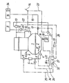
- an internal combustion engine which is provided with an oil pan 2, in which the lubricant is located.
- This lubricant is fed to the individual lubrication points of the internal combustion engine 1 via a circuit line 3, in which a lubricant pump 4 is switched on.
- a main flow filter 5 and a secondary flow filter 6 are provided for the separation of the solid fuels, but the arrangement of the main flow filter 5 alone is also sufficient.
- the circuit line 3 is connected to a pressure measuring device 7 which measures the lubricant pressure. Furthermore, a flow rate measuring device 8 is provided in the circuit line 3. Finally, a quantity measuring device 8 ′ can be arranged in the oil pan 2, which measures the lubricant level in the oil pan 2.
- the fuel for operating the internal combustion engine 1 passes from a fuel tank 9 via a fuel feed 10 to the injection pump 11 and from there via the injection line 12 to the individual injection nozzles. 13 represents the air filter connected to the injection line 12.
- the injection quantity is regulated in the usual way by the fuel pedal 14.
- the oil pan 2 is connected via a lubricant supply line 15 to a lubricant tank 16 containing fresh lubricant.
- a shut-off device 17 is arranged in the lubricant supply line 15.
- the oil pan 2 is connected via a lubricant discharge line 18, in which a shut-off element 19 is switched on, to an intermediate container 20, in which the used lubricant, which is discharged via the lubricant discharge line 18, is temporarily stored. From there, the used lubricant is fed by means of a feed pump 21 via a lei device 22 supplied to the air filter 13, whereby the used lubricant mixed with the fuel is injected into the cylinder spaces of the internal combustion engine 1.
- the line 22 can also be connected to the fuel return line, into which the used lubricant is then injected.
- the pump 21 is controlled via the fuel pedal 14, as indicated by the dashed line 23.
- This control can take place, for example, in that the pump 21 is electrically driven and in that an electrical switch actuated by the fuel pedal 14 is arranged in the power line to the pump. This ensures that used lubricant is only added to the fuel to be injected when the fuel pedal 14 is actuated. An addition of this used lubricating oil at idle is excluded.
- the feed pump 21 can also be controlled as a function of the speed of the internal combustion engine 1 using a tachometer (not shown) in the sense that the feed pump 21 is only switched on after a certain speed has been reached and thereby used lubricant is conveyed from the intermediate container 20 to the fuel supply 10.
- a tachometer not shown
- various parameters can be manually entered into the control device, as shown by the levers 32, which can assume three positions, for example.
- the levers 32 can assume three positions, for example.
- a quantity characterizing the alloy of the lubricant or a quantity characterizing the fuel used, in particular the sulfur content thereof into the control device 27 ′.
- a manual input of the external operating conditions of the motor vehicle driven by the internal combustion engine 1 for example the operating mode, the loading weight, the condition of the road, etc., can also be carried out.
- the control device 27 controls the shut-off elements 17 and 19, i.e. the supply of fresh lubricant from the lubricant tank 16 and the discharge of used lubricant into the intermediate container 20. This on the one hand ensures that the natural discharge of the lubricant during operation of the internal combustion engine 1 always is replaced, so that the required amount of lubricant is always available, on the other hand at a predetermined point in time, which is determined depending on the input variables of the control device 27, the lubricant is partially or completely renewed, in that by opening the shut-off device 19, the used lubricant removed and 17 new lubricant is supplied by opening the shut-off.
- the control device 27 also controls an alarm device 33, which responds if, for example, a further operation of the internal combustion engine 1 would damage the internal combustion engine 1 due to a sudden drop in pressure in the circuit line 3 or a sudden decrease in the amount of lubricant. Such a condition can occur, for example, if the lubricant pump 4 fails, if the main flow filter 5 is moved or if there is a leak in the circuit enter line 3.
- the lubricant tank 16 is expediently provided with a sight glass 34 or another quantity display, so that the content of the lubricant can be determined.
- a remote display similar to the remote display used for fuel tanks is also possible.
Landscapes
- Engineering & Computer Science (AREA)
- Mechanical Engineering (AREA)
- General Engineering & Computer Science (AREA)
- Chemical & Material Sciences (AREA)
- Combustion & Propulsion (AREA)
- Lubrication Of Internal Combustion Engines (AREA)
- Lubrication Details And Ventilation Of Internal Combustion Engines (AREA)
Applications Claiming Priority (2)
| Application Number | Priority Date | Filing Date | Title |
|---|---|---|---|
| AT436183 | 1983-12-15 | ||
| AT4361/83 | 1983-12-15 |
Publications (3)
| Publication Number | Publication Date |
|---|---|
| EP0146532A2 true EP0146532A2 (fr) | 1985-06-26 |
| EP0146532A3 EP0146532A3 (en) | 1986-11-12 |
| EP0146532B1 EP0146532B1 (fr) | 1989-03-15 |
Family
ID=3562994
Family Applications (1)
| Application Number | Title | Priority Date | Filing Date |
|---|---|---|---|
| EP19840890247 Expired EP0146532B1 (fr) | 1983-12-15 | 1984-12-17 | Procédé de commande d'un système de graissage pour des moteurs à combustion interne et dispositif pour exécuter le procédé |
Country Status (2)
| Country | Link |
|---|---|
| EP (1) | EP0146532B1 (fr) |
| DE (1) | DE3477225D1 (fr) |
Cited By (3)
| Publication number | Priority date | Publication date | Assignee | Title |
|---|---|---|---|---|
| GB2185077A (en) * | 1986-01-08 | 1987-07-08 | Idemitsu Kosan Co | Method and apparatus for lubricating a mechanical device |
| EP0303938A3 (en) * | 1987-08-18 | 1989-10-11 | Takano Corporation | Lubrication monitoring apparatus for machine |
| EP0928883A1 (fr) * | 1998-01-12 | 1999-07-14 | The Lubrizol Corporation | Dispositif pour maintenir la qualité et le niveau de lubrifiant dans un moteur a combustion |
Family Cites Families (8)
| Publication number | Priority date | Publication date | Assignee | Title |
|---|---|---|---|---|
| US2641277A (en) * | 1945-08-27 | 1953-06-09 | United Aircraft Prod | Fluid system damage control |
| GB867711A (en) * | 1956-09-29 | 1961-05-10 | Maschf Augsburg Nuernberg Ag | Means for creating a controlled consumption of lubricating oil in injection type internal combustion engines |
| DE2336522A1 (de) * | 1973-07-18 | 1975-02-06 | Kloeckner Humboldt Deutz Ag | Verfahren zur elektrischen und elektronischen ueberwachung und/oder steuerung einer brennkraftmaschine |
| DE2442746C3 (de) * | 1974-09-06 | 1979-01-04 | Daimler-Benz Ag, 7000 Stuttgart | Vorrichtung zur Messung des Ölverbrauchs |
| US4091894A (en) * | 1976-07-28 | 1978-05-30 | The Mechanex Corporation | Automatic oil level maintaining system |
| GB2084667B (en) * | 1980-09-29 | 1984-08-08 | Hurner Erwin Edward | Oil cleaning system |
| JPS6044490B2 (ja) * | 1981-07-29 | 1985-10-03 | 日産自動車株式会社 | エンジンオイル交換指示装置 |
| JPS5879610A (ja) * | 1981-11-04 | 1983-05-13 | Nissan Motor Co Ltd | 油圧低下警告装置 |
-
1984
- 1984-12-17 EP EP19840890247 patent/EP0146532B1/fr not_active Expired
- 1984-12-17 DE DE8484890247T patent/DE3477225D1/de not_active Expired
Cited By (6)
| Publication number | Priority date | Publication date | Assignee | Title |
|---|---|---|---|---|
| GB2185077A (en) * | 1986-01-08 | 1987-07-08 | Idemitsu Kosan Co | Method and apparatus for lubricating a mechanical device |
| FR2592703A1 (fr) * | 1986-01-08 | 1987-07-10 | Idemitsu Kosan Co | Procede et systeme pour le graissage d'un dispositif sous des conditions defavorables, notamment a haute temperature |
| GB2185077B (en) * | 1986-01-08 | 1990-08-15 | Idemitsu Kosan Co | Method and apparatus for lubricating a mechanical device |
| EP0303938A3 (en) * | 1987-08-18 | 1989-10-11 | Takano Corporation | Lubrication monitoring apparatus for machine |
| EP0928883A1 (fr) * | 1998-01-12 | 1999-07-14 | The Lubrizol Corporation | Dispositif pour maintenir la qualité et le niveau de lubrifiant dans un moteur a combustion |
| US5964318A (en) * | 1998-01-12 | 1999-10-12 | The Lubrizol Corporation | System for maintaining the quality and level of lubricant in an engine |
Also Published As
| Publication number | Publication date |
|---|---|
| EP0146532B1 (fr) | 1989-03-15 |
| EP0146532A3 (en) | 1986-11-12 |
| DE3477225D1 (en) | 1989-04-20 |
Similar Documents
| Publication | Publication Date | Title |
|---|---|---|
| DE69723131T2 (de) | Elektronische Steueranlage zum kontinuierlichen Ölwechseln | |
| DE69918193T2 (de) | Vorrichtung zur Aufrechthaltung der Ölqualität und des Ölstandes in einer Brennkraftmaschine | |
| DE69503704T2 (de) | Verfahren und Einrichtung zum Nachfüllen von Schmieröl in eine Brennkraftmaschine | |
| DE19933478A1 (de) | Kraftfahrzeug-Betankungssystem | |
| DE102011005394A1 (de) | System zum Warten von Verschleißteilen eines Fahrzeugs und Verfahren davon | |
| EP1027531B1 (fr) | Procede et dispositif permettant de lubrifier et simultanement d'alimenter en carburant un moteur a combustion interne | |
| EP1027532B1 (fr) | Procede et dispositif permettant de lubrifier et simultanement d'alimenter en carburant un moteur a combustion pouvant fonctionner a l'huile vegetale | |
| DE3337983C2 (de) | Verfahren und Vorrichtung zur kontinuierlichen Versorgung von Verbrennungsmotoren und/oder Hilfseinrichtungen davon mit Additiven | |
| DE69400818T2 (de) | Verfahren und Vorrichtung zur einstellbaren Dosierung eines Zusatzmittels zur Regenerierung für Partikelfilter | |
| DE3228195A1 (de) | Verfahren und vorrichtung zur ueberwachung des zeitpunkts des schmieroelwechsels fuer einen kraftfahrzeugmotor | |
| EP1434964B1 (fr) | Procede de lubrification d'au moins deux groupes d'un vehicule pourvu d'un moteur a combustion interne | |
| DE69723355T2 (de) | Verfahren und Einrichtung zum automatischen Zuführen von Schmiermittel unter Benutzung eines Mikrokomputers | |
| DE602004005492T2 (de) | System zur wartungsüberwachung eines in einem abgassystem eines kraftfahrzeugmotors angebrachten partikelfilters | |
| DE10112691C5 (de) | Verfahren zum Betreiben eines Zweitakt-Großdieselmotors sowie Zweitakt-Großdieselmotor | |
| EP0146532B1 (fr) | Procédé de commande d'un système de graissage pour des moteurs à combustion interne et dispositif pour exécuter le procédé | |
| DE3006903A1 (de) | Verfahren und vorrichtung zum austauschen des im oelsumpf einer brennkraftmaschine gesammelten schmieroels | |
| DE19902928C1 (de) | Schmiersystem für die Kolbengruppe einer Brennkraftmaschine sowie Verfahren zu dessen Steuerung | |
| DE4325194C2 (de) | Dieselmotorische Brennkraftmaschine | |
| DE102004043246A1 (de) | Automatische Zurücksetzung eines Schmierfluidlebensdauer-Überwachungssystems | |
| DE3906759C2 (de) | Verfahren und Vorrichtung zur Schmierung eines Verbrennungsmotors | |
| DE102009036228A1 (de) | Verfahren und Vorrichtung zur belastungsorientierten Schmierung von tribologischen Systemen | |
| DE584401C (de) | Schmierung fuer Brennkraftmaschinen | |
| DE102006034521B4 (de) | Verfahren zur Steuerung einer Motorölverdünnung eines Verbrennungsmotors | |
| EP3404224A1 (fr) | Dispositif de lubrification pour un gros moteur diesel, procédé de lubrification de cylindre d'un gros moteur diesel et gros moteur diesel | |
| DE1965609A1 (de) | Automatische Sicherheits-Vollschmierung fuer Arbeitsmaschinen mit variablem OElvorrat |
Legal Events
| Date | Code | Title | Description |
|---|---|---|---|
| PUAI | Public reference made under article 153(3) epc to a published international application that has entered the european phase |
Free format text: ORIGINAL CODE: 0009012 |
|
| AK | Designated contracting states |
Designated state(s): CH DE FR GB IT LI NL SE |
|
| RTI1 | Title (correction) | ||
| PUAL | Search report despatched |
Free format text: ORIGINAL CODE: 0009013 |
|
| AK | Designated contracting states |
Kind code of ref document: A3 Designated state(s): CH DE FR GB IT LI NL SE |
|
| 17P | Request for examination filed |
Effective date: 19861128 |
|
| 17Q | First examination report despatched |
Effective date: 19870625 |
|
| GRAA | (expected) grant |
Free format text: ORIGINAL CODE: 0009210 |
|
| AK | Designated contracting states |
Kind code of ref document: B1 Designated state(s): CH DE FR GB IT LI NL SE |
|
| ITF | It: translation for a ep patent filed | ||
| REF | Corresponds to: |
Ref document number: 3477225 Country of ref document: DE Date of ref document: 19890420 |
|
| GBT | Gb: translation of ep patent filed (gb section 77(6)(a)/1977) | ||
| ET | Fr: translation filed | ||
| PLBE | No opposition filed within time limit |
Free format text: ORIGINAL CODE: 0009261 |
|
| STAA | Information on the status of an ep patent application or granted ep patent |
Free format text: STATUS: NO OPPOSITION FILED WITHIN TIME LIMIT |
|
| 26N | No opposition filed | ||
| ITTA | It: last paid annual fee | ||
| PGFP | Annual fee paid to national office [announced via postgrant information from national office to epo] |
Ref country code: NL Payment date: 19901231 Year of fee payment: 7 Ref country code: FR Payment date: 19901231 Year of fee payment: 7 |
|
| PGFP | Annual fee paid to national office [announced via postgrant information from national office to epo] |
Ref country code: SE Payment date: 19910102 Year of fee payment: 7 |
|
| PGFP | Annual fee paid to national office [announced via postgrant information from national office to epo] |
Ref country code: GB Payment date: 19910121 Year of fee payment: 7 |
|
| PGFP | Annual fee paid to national office [announced via postgrant information from national office to epo] |
Ref country code: DE Payment date: 19910214 Year of fee payment: 7 |
|
| PG25 | Lapsed in a contracting state [announced via postgrant information from national office to epo] |
Ref country code: GB Effective date: 19911217 |
|
| PG25 | Lapsed in a contracting state [announced via postgrant information from national office to epo] |
Ref country code: SE Effective date: 19911218 |
|
| PGFP | Annual fee paid to national office [announced via postgrant information from national office to epo] |
Ref country code: CH Payment date: 19920429 Year of fee payment: 8 |
|
| PG25 | Lapsed in a contracting state [announced via postgrant information from national office to epo] |
Ref country code: NL Effective date: 19920701 |
|
| GBPC | Gb: european patent ceased through non-payment of renewal fee | ||
| NLV4 | Nl: lapsed or anulled due to non-payment of the annual fee | ||
| PG25 | Lapsed in a contracting state [announced via postgrant information from national office to epo] |
Ref country code: FR Effective date: 19920831 |
|
| PG25 | Lapsed in a contracting state [announced via postgrant information from national office to epo] |
Ref country code: DE Effective date: 19920901 |
|
| REG | Reference to a national code |
Ref country code: FR Ref legal event code: ST |
|
| PG25 | Lapsed in a contracting state [announced via postgrant information from national office to epo] |
Ref country code: LI Effective date: 19921231 Ref country code: CH Effective date: 19921231 |
|
| REG | Reference to a national code |
Ref country code: CH Ref legal event code: PL |
|
| EUG | Se: european patent has lapsed |
Ref document number: 84890247.4 Effective date: 19920704 |