EP0146533B1 - Backform mit beweglichem umfangsrand - Google Patents
Backform mit beweglichem umfangsrand Download PDFInfo
- Publication number
- EP0146533B1 EP0146533B1 EP83901381A EP83901381A EP0146533B1 EP 0146533 B1 EP0146533 B1 EP 0146533B1 EP 83901381 A EP83901381 A EP 83901381A EP 83901381 A EP83901381 A EP 83901381A EP 0146533 B1 EP0146533 B1 EP 0146533B1
- Authority
- EP
- European Patent Office
- Prior art keywords
- mould
- base
- constituting
- rims
- pivotable
- Prior art date
- Legal status (The legal status is an assumption and is not a legal conclusion. Google has not performed a legal analysis and makes no representation as to the accuracy of the status listed.)
- Expired
Links
- 235000014594 pastries Nutrition 0.000 title claims description 15
- 238000010411 cooking Methods 0.000 claims description 6
- 235000012976 tarts Nutrition 0.000 claims description 2
- 238000003466 welding Methods 0.000 claims description 2
- 210000002105 tongue Anatomy 0.000 claims 2
- 238000004519 manufacturing process Methods 0.000 claims 1
- 230000009466 transformation Effects 0.000 claims 1
- 238000000034 method Methods 0.000 description 4
- 239000000463 material Substances 0.000 description 3
- 101000852483 Homo sapiens Interleukin-1 receptor-associated kinase 1 Proteins 0.000 description 2
- 102100036342 Interleukin-1 receptor-associated kinase 1 Human genes 0.000 description 2
- 230000006835 compression Effects 0.000 description 2
- 238000007906 compression Methods 0.000 description 2
- 230000001788 irregular Effects 0.000 description 2
- 230000000284 resting effect Effects 0.000 description 2
- RYGMFSIKBFXOCR-UHFFFAOYSA-N Copper Chemical compound [Cu] RYGMFSIKBFXOCR-UHFFFAOYSA-N 0.000 description 1
- 238000004040 coloring Methods 0.000 description 1
- 230000000295 complement effect Effects 0.000 description 1
- 229910052802 copper Inorganic materials 0.000 description 1
- 239000010949 copper Substances 0.000 description 1
- 230000000694 effects Effects 0.000 description 1
- 239000002184 metal Substances 0.000 description 1
- 229910052751 metal Inorganic materials 0.000 description 1
- 230000001737 promoting effect Effects 0.000 description 1
- 230000002787 reinforcement Effects 0.000 description 1
- 238000000926 separation method Methods 0.000 description 1
- 229910001220 stainless steel Inorganic materials 0.000 description 1
- 239000010935 stainless steel Substances 0.000 description 1
Images

Classifications
-
- A—HUMAN NECESSITIES
- A21—BAKING; EDIBLE DOUGHS
- A21B—BAKERS' OVENS; MACHINES OR EQUIPMENT FOR BAKING
- A21B3/00—Parts or accessories of ovens
- A21B3/13—Baking-tins; Baking forms
-
- Y—GENERAL TAGGING OF NEW TECHNOLOGICAL DEVELOPMENTS; GENERAL TAGGING OF CROSS-SECTIONAL TECHNOLOGIES SPANNING OVER SEVERAL SECTIONS OF THE IPC; TECHNICAL SUBJECTS COVERED BY FORMER USPC CROSS-REFERENCE ART COLLECTIONS [XRACs] AND DIGESTS
- Y10—TECHNICAL SUBJECTS COVERED BY FORMER USPC
- Y10S—TECHNICAL SUBJECTS COVERED BY FORMER USPC CROSS-REFERENCE ART COLLECTIONS [XRACs] AND DIGESTS
- Y10S99/00—Foods and beverages: apparatus
- Y10S99/15—Pie pans
Definitions
- the invention relates to a pastry mold.
- the invention relates to a pastry mold of the kind comprising a bottom and a movable edge relative to this bottom, the molds of this type having in particular the aim of facilitating the release of the pastry baked inside of the latter.
- the mold comprises a bottom and a removable edge consisting of two semi-cylindrical half-parts provided with complementary means of assembly and the base of which is provided with a semi-cylindrical rim allowing the support of said bottom, when the different parts of this mold are assembled.
- the mold is constituted by a shovel to bake constituting its bottom and by an annular edge formed in one piece and articulated on the handle of the shovel, so that it can be lifted by pivoting around its axis of articulation.
- the mold comprises a bottom and a frustoconical wall executed in two half-parts, one of which is formed in one piece with the bottom, while the other is mounted with a downward pivoting ability and comprises, at its base, a crescent-shaped sole intended to support the semi-circular free edge of said bottom.
- This mold also has the drawback of causing irregular baking of the pastry because of the fact that its bottom does not have a uniform thickness over the whole of its surface when it is placed in the position of use for baking, this bottom having, in fact, in this situation, a double thickness on a half-part of its periphery, constituted by the addition of its own thickness and that of the support sole of the tilting half-part.
- the tilting half-part of the side wall of the mold has a natural tendency to tilt downwards, under the effect of its own weight, which presents a risk of burns for the person handling or transporting said mold. out of the oven.
- An object of the present invention is therefore to remedy the drawbacks of molds of the aforementioned type comprising a bottom and a removable or movable side wall, totally or in part.
- this objective is achieved thanks to a mold comprising a bottom and a movable edge executed in two half-parts or two half-edges, each of said half-edges constituting a half-perimeter of said movable edge, this mold being remarkable.
- each of the two half-edges constituting the movable edge is fixed, by its ends, to the bottom of said mold by means of articulations situated on a common axis, each of the two half-edges being mounted with a pivoting ability in direction from the top relative to said bottom.
- the mold thus executed has the advantages of allowing perfectly regular baking of its contents and of facilitating the release of the pastry from the mold after baking.
- the mold according to the invention makes it possible to obtain a better coloring and cooking of the crust arranged on the edge of the pastry, thanks to the fact that it is possible to slightly raise the movable half-edges, for example at mid-cooking.
- Another advantage of the mold according to the invention is that it can be used as a pie dish, after the two movable half-edges have been raised and placed perpendicular to the bottom of said mold, so as to constitute a handle allowing it to be grasped. and transport it.
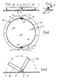
- This mold comprises a bottom 1, for example of circular shape, and an annular wall or movable edge executed in two half-parts or half-edges 2a, 2b which are fixed to the bottom 1 by means of two articulations 3, and are mounted with ability to pivot and lift relative to said bottom.
- the two half-edges 2a, 2b are mounted with an ability to pivot upwards, over at least 90 degrees, to a position in which they are placed perpendicular to the bottom 1 and arranged one at a time. inside the other, thus constituting a handle 2 ( Figure 5).
- the joints 3 are arranged in the median plane of the mold and, when the latter is circular, they are therefore diametrically opposite, so that when the two movable half-edges 2a, 2b are raised vertically, they are also placed in the median plane of the mold.
- the means for fixing the two pivoting half-parts 2a, 2b comprise, for example, according to a first embodiment suitable for producing the mold in rigid materials withstanding high temperatures (copper, thick stainless steel, etc.), two fastening tabs 4 diametrically opposite and integral with the bottom 1, these fastening tabs forming an angle of 90 degrees or an angle close to 90 degrees relative to said bottom.
- the fixing of the two pivoting half-edges 2a, 2b on the fastening tabs 4 is obtained by means of articulation pins 5 passing through holes made in said fastening tabs and in the ends of said half-edges.
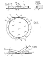
- the attachment tabs 4 can be obtained by cutting tabs in the bottom 1 and folding these tabs upwards, creating, on the edge of the mold, two open notches 6 diametrically opposite ( Figure 3) whose projecting edges are preferably rounded, that is to say two closed openings 7 leaving a circumferential edge 8 remaining (FIG. 6).
- the attachment tabs 4 can also be constituted by small brackets added by welding or otherwise against the upper face of the bottom 1, the wing 4a of said brackets by means of which the latter are fixed on said bottom being preferably directed outwards.
- the two pivoting half-parts 2a, 2b constituting the movable side wall of the mold can be smooth or grooved. They can, in their support position on the bottom 1, have an orientation perpendicular to said bottom or be slightly inclined relative to the perpendicular to said bottom, the attachment tabs 4 having a corresponding orientation.
- the means for fixing the two pivoting half-edges 2a, 2b comprise two wings 9 formed by two opposite portions of the plate constituting the bottom 1 folded upwards and forming, with the latter, an angle 90 degrees or an angle close to 90 degrees, each of these wings being, in the case of a circular plate, formed by a circular segment folded upwards according to a cord of said plate.
- the height of the folded wings or segments 9 corresponds to the height of the two half-parts 2a, 2b or substantially.
- the fixing of the two pivoting half-edges 2a, 2b on the wings or circular segments 9 is obtained by means of the hinge pins 5 passing through bores made in said wings and in the ends of said half-edges.
- the attachment and reinforcement wings 9 may have a position perpendicular to the bottom 1 when the two pivoting half-edges 2a, 2b are themselves oriented perpendicular to said bottom in their rest position on the latter, or have a slightly inclined position relative to the perpendicular to the bottom 1 when the two half-edges have an innate orientation relative to this perpendicular.
- This arrangement of the mold gives it better rigidity and is suitable for making it in materials having a propensity to deform under heat such as blued sheet metal for example.
- a system allowing the lateral release of the mobile edges 2a, 2b, prior to their raising, can be provided.
Landscapes
- Life Sciences & Earth Sciences (AREA)
- Engineering & Computer Science (AREA)
- Food Science & Technology (AREA)
- Food-Manufacturing Devices (AREA)
- Confectionery (AREA)
Claims (10)
Priority Applications (1)
| Application Number | Priority Date | Filing Date | Title |
|---|---|---|---|
| AT83901381T ATE29946T1 (de) | 1983-05-04 | 1983-05-10 | Backform mit beweglichem umfangsrand. |
Applications Claiming Priority (2)
| Application Number | Priority Date | Filing Date | Title |
|---|---|---|---|
| FR8307562A FR2545328B2 (fr) | 1983-05-04 | 1983-05-04 | Moule a tarte a bords mobiles |
| FR8307562 | 1983-05-04 |
Publications (2)
| Publication Number | Publication Date |
|---|---|
| EP0146533A1 EP0146533A1 (de) | 1985-07-03 |
| EP0146533B1 true EP0146533B1 (de) | 1987-09-30 |
Family
ID=9288650
Family Applications (1)
| Application Number | Title | Priority Date | Filing Date |
|---|---|---|---|
| EP83901381A Expired EP0146533B1 (de) | 1983-05-04 | 1983-05-10 | Backform mit beweglichem umfangsrand |
Country Status (5)
| Country | Link |
|---|---|
| US (1) | US4655430A (de) |
| EP (1) | EP0146533B1 (de) |
| DE (1) | DE3373861D1 (de) |
| FR (1) | FR2545328B2 (de) |
| WO (1) | WO1984004231A1 (de) |
Families Citing this family (3)
| Publication number | Priority date | Publication date | Assignee | Title |
|---|---|---|---|---|
| US4773320A (en) * | 1987-11-16 | 1988-09-27 | Stock Wilma L | Baking pan |
| FR2653650B1 (fr) * | 1989-10-26 | 1992-01-03 | Weber Dolores | Moules a tarte a formes multiples. |
| US9220277B1 (en) * | 2014-07-18 | 2015-12-29 | Michelle E. Allen | Form insert for use with a springform pan to make a uniform thickness crust |
Family Cites Families (14)
| Publication number | Priority date | Publication date | Assignee | Title |
|---|---|---|---|---|
| US667906A (en) * | 1900-07-13 | 1901-02-12 | Frank J Hanchett | Package-carrier. |
| US691463A (en) * | 1901-05-25 | 1902-01-21 | Grote Bottle Machine Company | Finishing-mold for making glass bottles. |
| US804122A (en) * | 1905-03-13 | 1905-11-07 | Charles J W Hayes | Mold for building-blocks. |
| FR463519A (fr) * | 1913-10-09 | 1914-02-25 | Armand Jean Roy | Machine pour la fabrication des bouteilles et objets en verre |
| US1527034A (en) * | 1924-03-22 | 1925-02-17 | Fred H Murray | Trap |
| US1862580A (en) * | 1928-09-21 | 1932-06-14 | Triumph Trap Company Inc | Game trap |
| US2081080A (en) * | 1936-06-15 | 1937-05-18 | Baker Edwin | Pattie mold |
| US2334595A (en) * | 1942-03-09 | 1943-11-16 | Philip S Bailey | Device for removing meats and the like from containers |
| US2598710A (en) * | 1947-10-06 | 1952-06-03 | Kaiser Aluminium Chem Corp | Container-carrier |
| US2682725A (en) * | 1951-11-05 | 1954-07-06 | Laurence M Atwood | Molding form |
| GB753068A (en) * | 1954-05-18 | 1956-07-18 | Gertrude Blount Houston | Pie tin |
| US3356044A (en) * | 1966-03-30 | 1967-12-05 | Maurice F Keathley | Fold-over pie forming unit |
| BE757535A (fr) * | 1969-05-29 | 1971-03-16 | Germain Bernard | Tourtiere semi-basculante avec couteau raclant |
| US4117965A (en) * | 1977-08-04 | 1978-10-03 | Allan Tackle Manufacturing Co., Inc. | Self-balancing tray |
-
1983
- 1983-05-04 FR FR8307562A patent/FR2545328B2/fr not_active Expired
- 1983-05-10 DE DE8383901381T patent/DE3373861D1/de not_active Expired
- 1983-05-10 WO PCT/FR1983/000089 patent/WO1984004231A1/fr not_active Ceased
- 1983-05-10 EP EP83901381A patent/EP0146533B1/de not_active Expired
- 1983-05-10 US US06/694,558 patent/US4655430A/en not_active Expired - Fee Related
Also Published As
| Publication number | Publication date |
|---|---|
| EP0146533A1 (de) | 1985-07-03 |
| DE3373861D1 (en) | 1987-11-05 |
| US4655430A (en) | 1987-04-07 |
| WO1984004231A1 (fr) | 1984-11-08 |
| FR2545328B2 (fr) | 1987-11-13 |
| FR2545328A2 (fr) | 1984-11-09 |
Similar Documents
| Publication | Publication Date | Title |
|---|---|---|
| EP2070459B1 (de) | Form zur Herstellung eines Lebensmittels auf der Basis von Teig, der unter Hitze aufgeht | |
| EP2339948B1 (de) | Vorrichtung zum zubereiten und garen von nahrungsmitteln und zugeordnetes elektrisches haushaltsgerät | |
| EP1491122B1 (de) | Elektrisches Haushaltsgerät | |
| EP1641344B1 (de) | Versteifte flexible backform | |
| WO2000044269A1 (fr) | Ustensile culinaire a manche de prehension amovible | |
| EP0961549A1 (de) | Formeinrichtung zur herstellung von schalen, insbesondere von essbaren schalen | |
| EP0162482B1 (de) | Fritierkorb mit Handgriff | |
| FR2680667A1 (fr) | Ustensile de cuisine a usages multiples. | |
| EP2201870A1 (de) | Druckkochgerät zum Zubereiten von Nahrungsmitteln mit Verschlussklammern mit vermindertem Gewicht und Herstellungsverfahren | |
| FR2859708A1 (fr) | Emballage pour aliments permettant une cuisson par vapeur desdits aliments | |
| CH630579A5 (fr) | Support amovible pour la manutention d'un objet. | |
| EP0146533B1 (de) | Backform mit beweglichem umfangsrand | |
| FR2613189A3 (fr) | Moule pour petits pains | |
| CA1257808A (fr) | Moule a patisserie | |
| EP2026687B1 (de) | Behälter zur wärmebehandlung von lebensmitteln | |
| FR2652248A1 (fr) | Tiroir pivotant pour cuisine ou analogue. | |
| FR2579869A1 (en) | Installation for manufacturing pizzas or the like | |
| FR2752374A1 (fr) | Dispositif releveur de produits, notamment de condiments, disposes dans un recipient | |
| WO2021165080A1 (fr) | Moule avec recipients amovibles a prehension facilitee et son support | |
| FR2737399A1 (fr) | Couvert ergonomique | |
| FR2650373A1 (fr) | Couvercle pour plaque de cuisson integrable dans des dessus de meubles de cuisine | |
| FR2653650A1 (fr) | Moules a tarte a formes multiples. | |
| EP4106590B1 (de) | Vielseitige form | |
| FR2863145A1 (fr) | Accessoire de parisserie associe a un module recevant une epaisseur de pate a cuire avec un bord peripherique releve | |
| WO2020064561A1 (fr) | Moule à paroi perforée |
Legal Events
| Date | Code | Title | Description |
|---|---|---|---|
| PUAI | Public reference made under article 153(3) epc to a published international application that has entered the european phase |
Free format text: ORIGINAL CODE: 0009012 |
|
| 17P | Request for examination filed |
Effective date: 19841122 |
|
| AK | Designated contracting states |
Designated state(s): AT BE CH DE GB LI LU NL SE |
|
| 17Q | First examination report despatched |
Effective date: 19860418 |
|
| GRAA | (expected) grant |
Free format text: ORIGINAL CODE: 0009210 |
|
| AK | Designated contracting states |
Kind code of ref document: B1 Designated state(s): AT BE CH DE GB LI LU NL SE |
|
| PG25 | Lapsed in a contracting state [announced via postgrant information from national office to epo] |
Ref country code: SE Effective date: 19870930 Ref country code: AT Effective date: 19870930 |
|
| REF | Corresponds to: |
Ref document number: 29946 Country of ref document: AT Date of ref document: 19871015 Kind code of ref document: T |
|
| REF | Corresponds to: |
Ref document number: 3373861 Country of ref document: DE Date of ref document: 19871105 |
|
| GBT | Gb: translation of ep patent filed (gb section 77(6)(a)/1977) | ||
| PLBE | No opposition filed within time limit |
Free format text: ORIGINAL CODE: 0009261 |
|
| STAA | Information on the status of an ep patent application or granted ep patent |
Free format text: STATUS: NO OPPOSITION FILED WITHIN TIME LIMIT |
|
| 26N | No opposition filed | ||
| PGFP | Annual fee paid to national office [announced via postgrant information from national office to epo] |
Ref country code: CH Payment date: 19900424 Year of fee payment: 8 |
|
| PGFP | Annual fee paid to national office [announced via postgrant information from national office to epo] |
Ref country code: NL Payment date: 19900531 Year of fee payment: 8 |
|
| PGFP | Annual fee paid to national office [announced via postgrant information from national office to epo] |
Ref country code: BE Payment date: 19900816 Year of fee payment: 8 |
|
| PG25 | Lapsed in a contracting state [announced via postgrant information from national office to epo] |
Ref country code: LI Effective date: 19910531 Ref country code: BE Effective date: 19910531 Ref country code: CH Effective date: 19910531 |
|
| BERE | Be: lapsed |
Owner name: WEBER DOLORES Effective date: 19910531 Owner name: WEBER VINCENT Effective date: 19910531 |
|
| PG25 | Lapsed in a contracting state [announced via postgrant information from national office to epo] |
Ref country code: NL Effective date: 19911201 |
|
| NLV4 | Nl: lapsed or anulled due to non-payment of the annual fee | ||
| REG | Reference to a national code |
Ref country code: CH Ref legal event code: PL |
|
| PGFP | Annual fee paid to national office [announced via postgrant information from national office to epo] |
Ref country code: GB Payment date: 19920617 Year of fee payment: 10 |
|
| PGFP | Annual fee paid to national office [announced via postgrant information from national office to epo] |
Ref country code: DE Payment date: 19921207 Year of fee payment: 10 |
|
| PGFP | Annual fee paid to national office [announced via postgrant information from national office to epo] |
Ref country code: LU Payment date: 19930414 Year of fee payment: 11 |
|
| PG25 | Lapsed in a contracting state [announced via postgrant information from national office to epo] |
Ref country code: GB Free format text: LAPSE BECAUSE OF NON-PAYMENT OF DUE FEES Effective date: 19930510 |
|
| EPTA | Lu: last paid annual fee | ||
| PG25 | Lapsed in a contracting state [announced via postgrant information from national office to epo] |
Ref country code: DE Effective date: 19940201 |
|
| GBPC | Gb: european patent ceased through non-payment of renewal fee |
Free format text: 5466, PAGE 176 |
|
| PG25 | Lapsed in a contracting state [announced via postgrant information from national office to epo] |
Ref country code: LU Free format text: LAPSE BECAUSE OF NON-PAYMENT OF DUE FEES Effective date: 19940510 |