EP0146821A2 - Installation de peinture pour peindre ou imprégner des objets, particulièrement des objets en bois - Google Patents
Installation de peinture pour peindre ou imprégner des objets, particulièrement des objets en bois Download PDFInfo
- Publication number
- EP0146821A2 EP0146821A2 EP84114544A EP84114544A EP0146821A2 EP 0146821 A2 EP0146821 A2 EP 0146821A2 EP 84114544 A EP84114544 A EP 84114544A EP 84114544 A EP84114544 A EP 84114544A EP 0146821 A2 EP0146821 A2 EP 0146821A2
- Authority
- EP
- European Patent Office
- Prior art keywords
- chains
- products
- couple
- rods
- impregnation
- Prior art date
- Legal status (The legal status is an assumption and is not a legal conclusion. Google has not performed a legal analysis and makes no representation as to the accuracy of the status listed.)
- Granted
Links
Images

Classifications
-
- B—PERFORMING OPERATIONS; TRANSPORTING
- B65—CONVEYING; PACKING; STORING; HANDLING THIN OR FILAMENTARY MATERIAL
- B65G—TRANSPORT OR STORAGE DEVICES, e.g. CONVEYORS FOR LOADING OR TIPPING, SHOP CONVEYOR SYSTEMS OR PNEUMATIC TUBE CONVEYORS
- B65G49/00—Conveying systems characterised by their application for specified purposes not otherwise provided for
- B65G49/02—Conveying systems characterised by their application for specified purposes not otherwise provided for for conveying workpieces through baths of liquid
- B65G49/04—Conveying systems characterised by their application for specified purposes not otherwise provided for for conveying workpieces through baths of liquid the workpieces being immersed and withdrawn by movement in a vertical direction
- B65G49/0409—Conveying systems characterised by their application for specified purposes not otherwise provided for for conveying workpieces through baths of liquid the workpieces being immersed and withdrawn by movement in a vertical direction specially adapted for workpieces of definite length
- B65G49/0436—Conveying systems characterised by their application for specified purposes not otherwise provided for for conveying workpieces through baths of liquid the workpieces being immersed and withdrawn by movement in a vertical direction specially adapted for workpieces of definite length arrangements for conveyance from bath to bath
- B65G49/044—Conveying systems characterised by their application for specified purposes not otherwise provided for for conveying workpieces through baths of liquid the workpieces being immersed and withdrawn by movement in a vertical direction specially adapted for workpieces of definite length arrangements for conveyance from bath to bath along a continuous circuit
- B65G49/045—Conveying systems characterised by their application for specified purposes not otherwise provided for for conveying workpieces through baths of liquid the workpieces being immersed and withdrawn by movement in a vertical direction specially adapted for workpieces of definite length arrangements for conveyance from bath to bath along a continuous circuit the circuit being fixed
-
- B—PERFORMING OPERATIONS; TRANSPORTING
- B05—SPRAYING OR ATOMISING IN GENERAL; APPLYING FLUENT MATERIALS TO SURFACES, IN GENERAL
- B05B—SPRAYING APPARATUS; ATOMISING APPARATUS; NOZZLES
- B05B13/00—Machines or plants for applying liquids or other fluent materials to surfaces of objects or other work by spraying, not covered by groups B05B1/00 - B05B11/00
- B05B13/02—Means for supporting work; Arrangement or mounting of spray heads; Adaptation or arrangement of means for feeding work
- B05B13/0221—Means for supporting work; Arrangement or mounting of spray heads; Adaptation or arrangement of means for feeding work characterised by the means for moving or conveying the objects or other work, e.g. conveyor belts
- B05B13/0264—Overhead conveying means, i.e. the object or other work being suspended from the conveying means; Details thereof, e.g. hanging hooks
Definitions
- the invention relates to a painting plant for painting or similar impregnation treatments of products, particularly wooden products, which is so designed as to permit high production rates to be obtained and which also is provided with small over-all sizes.
- transport devices are interconnected by at least a conveyor chain which is driven by conventional motors, to determine in this manner a progressive advancement of the transport devices and the products to be impregnated.
- This station is generally constituted by a series of fixed spraying nozzles, which are connected through suitable pipes to the reservoirs containing the impre gnating materials.
- the nozzles are situated at positions such as to determine the products to be sprayed from all sides and to be satisfactorily impregnated.
- tanks are provided below the products and the spraying nozzles, in order to collect the impregnating materials which have been di spersed during the spraying operation and to recover the same materials in a conventional manner.
- the impregnation of the products in this kind of plants may be obtained by a slow step-to-step advancement movement of the conveyor chain and the transport devices together with the products in the correspondence of the impregnation station.
- the impregnation operation may also be effected by a continuous advancement movement of the conveyor chain.
- the products are dried by the air or by introducing themselves into convection ovens of the conventional kind.
- the impregnated products are then moved through storage zones (storage units) which are deliberately foreseen.
- each product may be submitted to several successive impregnation treatments, performed in the same manner as above described, to obtain a complete finish thereof.
- the finished products are drawn by the respective transport devices and packed.
- Plants are also known, which are equipped with systems for driving the transport devices and the products which cause the amount of the products to be treated, under the same available space, to be increased.
- the products are drawn from the main handling chain and immerged into the impregnation tanks, by means of adequate mechanical and/or pneumatic devices.
- the scope of the invention is to realize an impregnation plant for products in such a way as to remarkably minimize the specified inconveniences and obtain high densities of the products to be treated, by a plant having compact overall dimensions, which fact permits to have productive capacities greater than those ones which now may be obtained.
- This plant is substantially based on the fact to utilize tubular rods on which the products to be treated are hanged up, said rods being arranged in a transver sal direction with respect to the handling chains, so permitting a greater products quantity to be transpor ted by taking advantage of the space in the tranversal direction too.
- the considered plant is so realized as to disengage the impregnation operation of the products from the main chain.
- an additional chain is provided and disposedin a perpendicular direction to the main chain, in order to move the products to be impregnated as well as those ones which have been impregnated, said additional chain being driven indepentently and with a different advancement frequency with respect to the main chain.
- this plant is of a simple type and permits considerable materials for its construction to be saved. Consequently, they are involved investments which are smaller than before for the installation of this kind of plants.
- this scope and the other ones may be obtained by means of a painting plant for painting or similar impregnation treatments of pro ducts, particularly wooden products, like window and door frames, blinds etc. which comprises transport means to support the products to be trea+ed and those ones which have been treated, which transport means in turn are supported by means of conventional sliding chains driven by per se known control means and also comprises impregnation means which are constituted by at least a collecting tank associated with spraying nozzles or similar devices, which are connected to the reservoirs containing the respective impregnating materials.
- Such a plant is characterized in that said transport means are constituted by a series of tubular rods, which are removably supported on at least a first and a second couple of sliding chains, parallel each other and which rods are preferably disposed in a transverse direction to the same chains, a plurality of products being connected to each of said tubular rods and tran sfer means being also provided for drawing said rods together with the products to be treated from said first couple of chains and shifting them towards said impregnation means as well as for disposing said rods together with the impregnated products onto said second couple of chains.
- the plant is substantially constituted by several couples of conventional sliding chains, which are reciprocally separated and preferably disposed in a horizontal plane.
- each couple of the chains 4 and 5 is wound around two respective couples of wheels 6,7 and 8 (the last couple of wheels isn't shown) and is driven in the same rotation direction (arrow A) by means of respective motors of the conventional type (which aren't shown).
- tubular rods 9 are removably applied onto the couple of chains 4, said tubular rods being reciprocally spaced at regular intervals and being able to support the products 10 to be treated and to transport them towards the advancement direction of the chains, said rods being in turn supported in the transversal direction by the respective chains of the couple of chains 4 and 5.
- the products to be treated may be constituted by wooden products like window and door frames, blinds etc. or also by products constitu ted by other materials.
- an additional couple of chains 11 of convetional type is provided, whose chains are laterally and outwardly shifted there from and also are disposed in a perpendi cular direction to the corresponding chains of the couple 4.
- the couple of chains 11 is constituted by chains of the same lenght, which are disposed parallel each other and wound around the respective couples of wheels 12,13,14, 15,16,17,18.
- the couple of chains 11 is separated from the couples of chains 4 and 5 and is driven in the direction of the arrow B, indepentently from the latter, by means of at least a conventional motor (not shown).
- the scope of the couple of chains 11 is to taken the tubular rods 9, supporting the relevant products 10 to be treated, from the couple of chains 4 and to transport them in correspondence of an impregnation station 19.
- This latter is constituted by a series of fixed spraying nozzles 20, which are connected through adequate pipings to the reservoirs containing the employed impregnating materials (the pipings and reservoirs aren't shown).
- the nozzles 20 are arranged in such positions as to spray each product from all sides, so as to impregnate it in a satisfactory way, said nozzles being also included within a collecting tank 21, which is adequa tely dimensioned and is capable to receive the products to be treated.
- such a tank permits the impregnating materials which have been dispersed during the treatment of the products to be collected and recovered in a conventional manner.
- the tubular rods supporting the impregnated products are then transferred by means of the couple of chains 11, on the couple of chains 5 which in turn transport them slowly to permit them to be dried in air or within the forced convection ovens, which have been deliberately foreseen (not shown).
- the figure does not show the remaining portion of the plant, of conventional type, through which the impregnated products may be again shifted, if requested, in correspondence of the couple of chains 4 to carry out further treatments of the same products in the same manner as described, which products finally may be shifted in correspondence of the unload station (not shown), in which such products are drawn and packed.
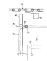
- fig. 2 it is shown the manner in which each tubular rod 9 is transferred on the couple of chains 4.
- this figure only shows a portion of the rod 9 and also a relative chain of the couples 4 and 11 only.
- the rod 9 is provided with.a collar 22 at each end thereof, which collar is removably inserted into a corresponding fork element 23 provided on the respective chain of the couple 4.
- each chain has a continuous series of fork elements 23, which are reciprocally spaced to accomo- date as many tubular rods 9 and distributed in a continuous manner along the same chain.
- each chain of the couple of chains 11 is provided with a series of entrainment arms 24, which are hinged along the chain at regular intervals and laterally projecting therefrom, in such a manner as to interact with the projecting end portion 25 of each rod 9, when the latter is put on the couple of chains 4 as above described.
- the plant so constituted operates in the following way: the products to be impregnated are initially hanged up, by the personnel, on the rods 9 which are supported by the couple of chains 4 as previously described.
- this couple of chains is slowly moved with a step-to-step advancement movement, until a rod together with the relative products arrives in correspondence of the couple of chains 11, which initially is still.
- every entrainment arm 24 acts against the projecting end portions 25 or each rod and causes the latter to be raised together with the relative products, along the advancement path of the couple of chains 11.
- the couple of chains 4 is driven again, to predispose the next rod, together with the relative products, to be raised in a similar manner.
- every rod together with the products to be treated is lowered by means of the couple of chains 11 into the collecting tank 21 and at the same time the advancement movement of this couple of chains is stopped, until the impregna tion operation of all the products is ended; then, the inverse operation is carried out by shifting the rods towards the couple of chains 5.
- the couple of chains 11 provided for tran sporting the products to be treated towards the impregnation station 19 and for removing from this station the treated products, with a movement which is indepen dent from that one of the couples of chains 4 and 5. Consequently, by adequately dimensioning the sliding path of the couple of chains 11 and setting its advan cement frequency in a different manner than that one of the couples of chains 4 and 5, it is possible time to time to obtain different productive capacities so that variable quantities of products may be impregnated.
- the plant so obtained permits the products with a density which is higher than that one of the conventional plants to be transported and treated, above all due to the fact that the products are hanged up transversally on the tubular rods.
- the plant according to the invention may also be realized in a different manner than that one described, permitting also the same advantages to be obtained.
- a further impregnation plant is shown, which comprises three couples of chains 25,26,27 which are separated and indipendent each other as well' as realized and operated in the same manner as above de scribed.
- the couple of chains 26 has a les ser development in a vertical direction and consequently a sliding path which is shorter than before.
- this couple of chains is so shaped as that the products to be treated are horizontally shifted in a rectilinear direction, in correspondence of the impregnation station 28, which is formed by a lower fixed collecting tank 29 and a truck 30, which is vertically movable in the direction of the arrows C by means of a further couple of chains 31 and which is provided with a series of spraying nozzles 32.
- the tank 29 and the nozzles 32 are formed and operated in the same principle as previously described. Therefore, at the treatment position in which the pro ducts remain suspended above the tank 29 and the truck 30, the couple of chains 26 is stopped and at the same time the truck 30, which initially is disposed on the position shown in the figure, is slowly lifted. Conseauently, the products become completely impregnated; then, the truck 30 is lowered and the couple of chains 26 is driven, so causing the treated products to be removed from the impregnation station 28 and fur ther products to be treated to be predisposed in corre spondence of this station.
- the considered plant may be realized in different versions which are based on the same functional principle, without departing anyway from the protection sphere of the present invention.
Landscapes
- Chemical And Physical Treatments For Wood And The Like (AREA)
- Coating Apparatus (AREA)
Priority Applications (1)
| Application Number | Priority Date | Filing Date | Title |
|---|---|---|---|
| AT84114544T ATE40960T1 (de) | 1983-12-01 | 1984-11-30 | Anlage zum anstreichen oder impraegnieren von gegenstaende, insbesondere gegenstaenden aus holz. |
Applications Claiming Priority (2)
| Application Number | Priority Date | Filing Date | Title |
|---|---|---|---|
| IT8252883 | 1983-12-01 | ||
| IT82528/83A IT1175032B (it) | 1983-12-01 | 1983-12-01 | Impianto di verniciatura o trattamenti d'impregnazione simili di prodotti, in particolare di prodotti di legno |
Publications (3)
| Publication Number | Publication Date |
|---|---|
| EP0146821A2 true EP0146821A2 (fr) | 1985-07-03 |
| EP0146821A3 EP0146821A3 (en) | 1986-02-05 |
| EP0146821B1 EP0146821B1 (fr) | 1989-03-01 |
Family
ID=11318388
Family Applications (1)
| Application Number | Title | Priority Date | Filing Date |
|---|---|---|---|
| EP84114544A Expired EP0146821B1 (fr) | 1983-12-01 | 1984-11-30 | Installation de peinture pour peindre ou imprégner des objets, particulièrement des objets en bois |
Country Status (4)
| Country | Link |
|---|---|
| EP (1) | EP0146821B1 (fr) |
| AT (1) | ATE40960T1 (fr) |
| DE (1) | DE3476852D1 (fr) |
| IT (1) | IT1175032B (fr) |
Family Cites Families (6)
| Publication number | Priority date | Publication date | Assignee | Title |
|---|---|---|---|---|
| US2103901A (en) * | 1935-02-14 | 1937-12-28 | Parker Rust Proof Co | Conveyer mechanism |
| US2434125A (en) * | 1941-10-01 | 1948-01-06 | Howard V Schweitzer | Painting method |
| US2769728A (en) * | 1952-05-22 | 1956-11-06 | Ranshurg Electro Coating Corp | Apparatus for and method of conveying articles |
| LU54585A1 (fr) * | 1967-02-24 | 1967-12-05 | ||
| FR2261146A1 (en) * | 1974-02-20 | 1975-09-12 | Saunal Pierre | Apparatus for painting both sides of articles - spaced chains carry suspended articles along U shaped path past sprays |
| DE3270105D1 (en) * | 1981-08-03 | 1986-04-30 | Mitsubishi Rayon Co | Method and apparatus for surface-hardening treatment of synthetic resin articles |
-
1983
- 1983-12-01 IT IT82528/83A patent/IT1175032B/it active
-
1984
- 1984-11-30 EP EP84114544A patent/EP0146821B1/fr not_active Expired
- 1984-11-30 AT AT84114544T patent/ATE40960T1/de not_active IP Right Cessation
- 1984-11-30 DE DE8484114544T patent/DE3476852D1/de not_active Expired
Also Published As
| Publication number | Publication date |
|---|---|
| ATE40960T1 (de) | 1989-03-15 |
| EP0146821B1 (fr) | 1989-03-01 |
| EP0146821A3 (en) | 1986-02-05 |
| IT8382528A0 (it) | 1983-12-01 |
| IT1175032B (it) | 1987-07-01 |
| DE3476852D1 (en) | 1989-04-06 |
Similar Documents
| Publication | Publication Date | Title |
|---|---|---|
| EP4023570B1 (fr) | Robot de tri et procédé de tri | |
| EP0956163B1 (fr) | Installation de nettoyage industriel | |
| US4406570A (en) | Materials handling system | |
| US3960276A (en) | Transporter for flat workpieces | |
| DE102008025778A1 (de) | Anlage zum Be- und Entladen von Hochregalen | |
| US5025912A (en) | Shuttle type conveyor | |
| CN108217122A (zh) | 货梯物流全自动转运机 | |
| US4252486A (en) | System for transferring and storing elongated elements | |
| EP0146821A2 (fr) | Installation de peinture pour peindre ou imprégner des objets, particulièrement des objets en bois | |
| DE3442161A1 (de) | Einrichtung zum umladen von auf unterlagen angeordneten keramischen formlingen | |
| US4483718A (en) | Method and apparatus for cleaning machined parts | |
| US4923354A (en) | Magazine with movable shelves, for the maturation of cakes of synthetic foam material | |
| US3252603A (en) | Shuttle conveying machine with independently elevatable load engaging means | |
| DE2711677C2 (de) | Palettenbe- oder Entladevorrichtung | |
| EP0334460B1 (fr) | Tranporteur à plancher avec des longerons parallèles à transport pour une installation de compostage | |
| DE2356133A1 (de) | Behandeln von steinen und formen von aussparungen in lagen von ziegelsteinen | |
| CN207014539U (zh) | 一种混凝土预制品生产线 | |
| US3599417A (en) | Method of placing packages of strand on a twist frame | |
| US2933212A (en) | Processing machine with individual elevators | |
| US3255897A (en) | Apparatus for conveying and treating articles | |
| US3543486A (en) | Method of harvesting fruit | |
| US3499551A (en) | Apparatus for loading bagged mail from a loading dock into a highway vehicle | |
| DE4109294A1 (de) | Lasten-transfervorrichtung | |
| JPH03295649A (ja) | 自動スクリーン捺染機におけるスクリーン枠の交換装置 | |
| CN207956903U (zh) | 货梯物流全自动转运机 |
Legal Events
| Date | Code | Title | Description |
|---|---|---|---|
| PUAI | Public reference made under article 153(3) epc to a published international application that has entered the european phase |
Free format text: ORIGINAL CODE: 0009012 |
|
| AK | Designated contracting states |
Designated state(s): AT BE CH DE FR GB LI NL SE |
|
| PUAL | Search report despatched |
Free format text: ORIGINAL CODE: 0009013 |
|
| AK | Designated contracting states |
Designated state(s): AT BE CH DE FR GB LI NL SE |
|
| 17P | Request for examination filed |
Effective date: 19860521 |
|
| 17Q | First examination report despatched |
Effective date: 19870722 |
|
| GRAA | (expected) grant |
Free format text: ORIGINAL CODE: 0009210 |
|
| AK | Designated contracting states |
Kind code of ref document: B1 Designated state(s): AT BE CH DE FR GB LI NL SE |
|
| PG25 | Lapsed in a contracting state [announced via postgrant information from national office to epo] |
Ref country code: SE Effective date: 19890301 Ref country code: LI Effective date: 19890301 Ref country code: CH Effective date: 19890301 |
|
| REF | Corresponds to: |
Ref document number: 40960 Country of ref document: AT Date of ref document: 19890315 Kind code of ref document: T |
|
| REF | Corresponds to: |
Ref document number: 3476852 Country of ref document: DE Date of ref document: 19890406 |
|
| REG | Reference to a national code |
Ref country code: CH Ref legal event code: PL |
|
| ET | Fr: translation filed | ||
| PLBE | No opposition filed within time limit |
Free format text: ORIGINAL CODE: 0009261 |
|
| STAA | Information on the status of an ep patent application or granted ep patent |
Free format text: STATUS: NO OPPOSITION FILED WITHIN TIME LIMIT |
|
| 26N | No opposition filed | ||
| PGFP | Annual fee paid to national office [announced via postgrant information from national office to epo] |
Ref country code: GB Payment date: 19901126 Year of fee payment: 7 Ref country code: FR Payment date: 19901126 Year of fee payment: 7 |
|
| PGFP | Annual fee paid to national office [announced via postgrant information from national office to epo] |
Ref country code: BE Payment date: 19901129 Year of fee payment: 7 |
|
| PGFP | Annual fee paid to national office [announced via postgrant information from national office to epo] |
Ref country code: NL Payment date: 19901130 Year of fee payment: 7 Ref country code: AT Payment date: 19901130 Year of fee payment: 7 |
|
| PGFP | Annual fee paid to national office [announced via postgrant information from national office to epo] |
Ref country code: DE Payment date: 19910129 Year of fee payment: 7 |
|
| PG25 | Lapsed in a contracting state [announced via postgrant information from national office to epo] |
Ref country code: GB Effective date: 19911130 Ref country code: BE Effective date: 19911130 Ref country code: AT Effective date: 19911130 |
|
| BERE | Be: lapsed |
Owner name: VIDALI MARZIO Effective date: 19911130 |
|
| PG25 | Lapsed in a contracting state [announced via postgrant information from national office to epo] |
Ref country code: NL Effective date: 19920601 |
|
| NLV4 | Nl: lapsed or anulled due to non-payment of the annual fee | ||
| GBPC | Gb: european patent ceased through non-payment of renewal fee | ||
| PG25 | Lapsed in a contracting state [announced via postgrant information from national office to epo] |
Ref country code: FR Effective date: 19920731 |
|
| PG25 | Lapsed in a contracting state [announced via postgrant information from national office to epo] |
Ref country code: DE Effective date: 19920801 |
|
| REG | Reference to a national code |
Ref country code: FR Ref legal event code: ST |