EP0146821B1 - Installation de peinture pour peindre ou imprégner des objets, particulièrement des objets en bois - Google Patents
Installation de peinture pour peindre ou imprégner des objets, particulièrement des objets en bois Download PDFInfo
- Publication number
- EP0146821B1 EP0146821B1 EP84114544A EP84114544A EP0146821B1 EP 0146821 B1 EP0146821 B1 EP 0146821B1 EP 84114544 A EP84114544 A EP 84114544A EP 84114544 A EP84114544 A EP 84114544A EP 0146821 B1 EP0146821 B1 EP 0146821B1
- Authority
- EP
- European Patent Office
- Prior art keywords
- chains
- products
- couple
- painting
- impregnating
- Prior art date
- Legal status (The legal status is an assumption and is not a legal conclusion. Google has not performed a legal analysis and makes no representation as to the accuracy of the status listed.)
- Expired
Links
Images

Classifications
-
- B—PERFORMING OPERATIONS; TRANSPORTING
- B65—CONVEYING; PACKING; STORING; HANDLING THIN OR FILAMENTARY MATERIAL
- B65G—TRANSPORT OR STORAGE DEVICES, e.g. CONVEYORS FOR LOADING OR TIPPING, SHOP CONVEYOR SYSTEMS OR PNEUMATIC TUBE CONVEYORS
- B65G49/00—Conveying systems characterised by their application for specified purposes not otherwise provided for
- B65G49/02—Conveying systems characterised by their application for specified purposes not otherwise provided for for conveying workpieces through baths of liquid
- B65G49/04—Conveying systems characterised by their application for specified purposes not otherwise provided for for conveying workpieces through baths of liquid the workpieces being immersed and withdrawn by movement in a vertical direction
- B65G49/0409—Conveying systems characterised by their application for specified purposes not otherwise provided for for conveying workpieces through baths of liquid the workpieces being immersed and withdrawn by movement in a vertical direction specially adapted for workpieces of definite length
- B65G49/0436—Conveying systems characterised by their application for specified purposes not otherwise provided for for conveying workpieces through baths of liquid the workpieces being immersed and withdrawn by movement in a vertical direction specially adapted for workpieces of definite length arrangements for conveyance from bath to bath
- B65G49/044—Conveying systems characterised by their application for specified purposes not otherwise provided for for conveying workpieces through baths of liquid the workpieces being immersed and withdrawn by movement in a vertical direction specially adapted for workpieces of definite length arrangements for conveyance from bath to bath along a continuous circuit
- B65G49/045—Conveying systems characterised by their application for specified purposes not otherwise provided for for conveying workpieces through baths of liquid the workpieces being immersed and withdrawn by movement in a vertical direction specially adapted for workpieces of definite length arrangements for conveyance from bath to bath along a continuous circuit the circuit being fixed
-
- B—PERFORMING OPERATIONS; TRANSPORTING
- B05—SPRAYING OR ATOMISING IN GENERAL; APPLYING FLUENT MATERIALS TO SURFACES, IN GENERAL
- B05B—SPRAYING APPARATUS; ATOMISING APPARATUS; NOZZLES
- B05B13/00—Machines or plants for applying liquids or other fluent materials to surfaces of objects or other work by spraying, not covered by groups B05B1/00 - B05B11/00
- B05B13/02—Means for supporting work; Arrangement or mounting of spray heads; Adaptation or arrangement of means for feeding work
- B05B13/0221—Means for supporting work; Arrangement or mounting of spray heads; Adaptation or arrangement of means for feeding work characterised by the means for moving or conveying the objects or other work, e.g. conveyor belts
- B05B13/0264—Overhead conveying means, i.e. the object or other work being suspended from the conveying means; Details thereof, e.g. hanging hooks
Definitions
- the invention relates to a painting plant for painting or impregnating products, such as wooden products, by means of spraying operations.
- such transport means are constituted by a series of tubular rods, onto which the products are hung, which rods are removably supported by a couple of parallel chains and are disposed in a transversal direction of the same chains.
- the conveying mechanism referred to comprises transfer means constituted by a further couple of sliding chains provided with driving means and which is able to draw the rods, together with the products to be treated, from the couple of chains, to shift them towards the tank for immersing the same products in the impregnating liquid contained therein, and then to dispose the already treated products back to the same couple of chains, which provides also for transporting these products towards the drying chamber.
- the present invention provides a painting plant of the kind disclosed by the above mentioned U.S. patent, in which however the transfer means are combined with impregnating means shaped and operated in a different way, in such a manner as to obtain a compact plant with small overall dimensions and high productive capacities.
- This painting plant is realized according to claim 1.
- the plant is substantially constituted by several couples of conventional sliding chains, which are reciprocally separated.
- each couple 4 and 5 of sliding chains each of them being constituted by two chains having the same length and disposed parallel each other in a transversal direction thereof.
- each couple 4, 5 of chains is wound around two respective couples of wheels 6, 7 and 8 (the last couple of wheels isn't shown) and is driven in the same rotation direction (arrow A) by means of respective motors of the conventional type (which aren't shown), so that the parallel parts of the two chains forming each couple are disposed in a horizontal plane.
- tubular rods 9 are provided in the plant referred to and act as transport means able to support a plurality of products 10 to be treated as well as the treated products.
- tubular rods are removably supported on the parallel sliding chains of each couple 4, 5, by arranging them in a transversal direction with respect to the relevant sliding chains, so that the tubular rods 9 are reciprocally spaced at regular intervals along the relevant sliding chains of each couple 4, 5 and are shifted by the same in the advancement direction thereof.
- the products to be treated may be constituted by wooden products like window and door frames, blinds etc. or also by products constituted by other materials.
- transfer means constituted by an additional couple 11 of sliding chains of conventional type, whose chains are laterally and outwardly shifted from the correspondent chains of the couple 4 and also are disposed in a perpendicular direction to these latter chains.
- the couple 11 of chains is constituted by sliding chains of the same length, which are disposed parallel each other in a transversal direction thereof and wound around the respective couples of wheels 12,13,14,15,16,17, 18.
- the couple 11 of chains is separated from the couples 4 and 5 of chains and is driven in the direction of the arrow B, independently from the latter, by means of at least a conventional motor (not shown).
- the scope of the couple 11 of chains is to draw the tubular rods 9, supporting the relevant products 10, to be treated, from the couple 4 of chains and to shift them in correspondence of impregnating means 19.
- These latter are constituted by a series of fixed spraying nozzles 20, which are connected through adequate pipings to the reservoirs containing the employed impregnating materials (the pipings and reservoirs aren't shown).
- the nozzles 20 are arranged in such position as to spray each product from all sides, so as to impregnate it in a satisfactory way, said nozzles being also included within a collecting tank 21, which is adequately dimensioned and is capable to receive the products to be treated.
- such a tank permits the impregnating materials which have been dispersed during the painting or impregnating treatment of the products to be collected and recovered in a conventional manner.
- the tubular rods supporting the impregnated products are then transferred, by means of the couple 11 of chains, to the couple 5 of chains which in turn transports them slowly to permit them to be dried in air or within the forced convection ovens, which have been deliberately foreseen (not shown).
- the figure does not show the remaining portion of the plant, of conventional type, through which the impregnated products may be again shifted, if requested, in correspondence of the couple 4 of chains to carry out further treatments of the same products in the same manner as described, which products finally may be shifted in correspondence of the unload station (not shown), in which such products are drawn and packed.
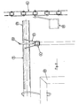
- Fig. 2 it is shown the manner in which each tubualr rod 9 is tranferred on the couple 4 of chains.
- this figure only shows a portion of the rod 9 and also a relative chain of the couples 4 and 11 only.
- the rod 9 is provided with a collar 22 at each end thereof, which collar is removably inserted into a corresponding fork element 23 provided on the respective chain of the couple 4.
- each chain has a continuous series of fork elements 23, which are reciprocally spaced to accommodate as many tubular rods 9 and distributed in a continuous manner along the same chain.
- each chain of the couple 11 of chains is provided with a series of entrainment arms 24, which are hinged along the chain at regular intervals and laterally projecting therefrom, in such a manner as to interact with the projecting end portion 25 of each rod 9, when the latter is put on the couple 4 of chains as above described.
- the plant so constituted operates in the following way: the products to be impregnated are initially hanged up, by the personnel, on the rods 9 which are supported by the couple 4 of chains as previously described. Then, this couple of chains is slowly moved with a step-to-step advancement movement, until a rod together with the relative products arrives in correspondence of the couple 11 of chains, which initially is still. At this point, the movement of the couple 4 of chains is stopped and the couple 11 of chains is moved in its vertical advancement direction B.
- every entrainment arm 24 acts against the projecting end portions 25 of each rod and causes the latter to be raised together with the relative products, along the advancement path of the couple 11 of chains.
- every rod together with the products to be treated is lowered by means of the couple 11 of chains into the collecting tank 21 and at the same time the advancement movement of this couple of chains is stopped, until the impregnating operation of all the products is ended; then, the inverse operation is carried out by shifting the rods towards the couple 5 of chains.
- the couple 11 of chains provides for shifting the products to be treated towards the impregnating means 19 and for removing from these means the treated products, with a movement which is independent from that one of the couples 4 and 5 of chains.
- a painting plant which comprises three couples 26, 27, 28 of chains, which are separated and independent each other as well as realized and operated in the same manner as above described.
- the couple 27 of chains has a lesser development in a vertical direction and consequently a sliding path which is shorter than before.
- this couple of chains is so shaped as that the products to be treated are horizontally shifted in a rectilinear direction, in correspondence of the impregnating means 29, which are formed by a lower fixed collecting tank 30 and a truck 31, which is vertically movable in the direction of the arrows C by means of a further couple 32 of chains and which is provided with a series of spraying nozzles 33.
- the tank 30 and the nozzles 33 are formed and operated in the same principle as previously described.
Landscapes
- Chemical And Physical Treatments For Wood And The Like (AREA)
- Coating Apparatus (AREA)
Claims (4)
Priority Applications (1)
| Application Number | Priority Date | Filing Date | Title |
|---|---|---|---|
| AT84114544T ATE40960T1 (de) | 1983-12-01 | 1984-11-30 | Anlage zum anstreichen oder impraegnieren von gegenstaende, insbesondere gegenstaenden aus holz. |
Applications Claiming Priority (2)
| Application Number | Priority Date | Filing Date | Title |
|---|---|---|---|
| IT8252883 | 1983-12-01 | ||
| IT82528/83A IT1175032B (it) | 1983-12-01 | 1983-12-01 | Impianto di verniciatura o trattamenti d'impregnazione simili di prodotti, in particolare di prodotti di legno |
Publications (3)
| Publication Number | Publication Date |
|---|---|
| EP0146821A2 EP0146821A2 (fr) | 1985-07-03 |
| EP0146821A3 EP0146821A3 (en) | 1986-02-05 |
| EP0146821B1 true EP0146821B1 (fr) | 1989-03-01 |
Family
ID=11318388
Family Applications (1)
| Application Number | Title | Priority Date | Filing Date |
|---|---|---|---|
| EP84114544A Expired EP0146821B1 (fr) | 1983-12-01 | 1984-11-30 | Installation de peinture pour peindre ou imprégner des objets, particulièrement des objets en bois |
Country Status (4)
| Country | Link |
|---|---|
| EP (1) | EP0146821B1 (fr) |
| AT (1) | ATE40960T1 (fr) |
| DE (1) | DE3476852D1 (fr) |
| IT (1) | IT1175032B (fr) |
Family Cites Families (6)
| Publication number | Priority date | Publication date | Assignee | Title |
|---|---|---|---|---|
| US2103901A (en) * | 1935-02-14 | 1937-12-28 | Parker Rust Proof Co | Conveyer mechanism |
| US2434125A (en) * | 1941-10-01 | 1948-01-06 | Howard V Schweitzer | Painting method |
| US2769728A (en) * | 1952-05-22 | 1956-11-06 | Ranshurg Electro Coating Corp | Apparatus for and method of conveying articles |
| LU54585A1 (fr) * | 1967-02-24 | 1967-12-05 | ||
| FR2261146A1 (en) * | 1974-02-20 | 1975-09-12 | Saunal Pierre | Apparatus for painting both sides of articles - spaced chains carry suspended articles along U shaped path past sprays |
| DE3270105D1 (en) * | 1981-08-03 | 1986-04-30 | Mitsubishi Rayon Co | Method and apparatus for surface-hardening treatment of synthetic resin articles |
-
1983
- 1983-12-01 IT IT82528/83A patent/IT1175032B/it active
-
1984
- 1984-11-30 EP EP84114544A patent/EP0146821B1/fr not_active Expired
- 1984-11-30 AT AT84114544T patent/ATE40960T1/de not_active IP Right Cessation
- 1984-11-30 DE DE8484114544T patent/DE3476852D1/de not_active Expired
Also Published As
| Publication number | Publication date |
|---|---|
| ATE40960T1 (de) | 1989-03-15 |
| EP0146821A2 (fr) | 1985-07-03 |
| EP0146821A3 (en) | 1986-02-05 |
| IT8382528A0 (it) | 1983-12-01 |
| IT1175032B (it) | 1987-07-01 |
| DE3476852D1 (en) | 1989-04-06 |
Similar Documents
| Publication | Publication Date | Title |
|---|---|---|
| US2116430A (en) | Conveying mechanism | |
| JP2001509077A (ja) | 工業用洗浄設備 | |
| ITBO990090A1 (it) | Metodo ed impianto per la verniciatura di infissi in legno , particolarmente di finestre , porte - finestre o simili . | |
| US3022791A (en) | Mobile type cleaning unit | |
| EP0201256A2 (fr) | Installation pour l'imprégnation d'articles | |
| EP0146821B1 (fr) | Installation de peinture pour peindre ou imprégner des objets, particulièrement des objets en bois | |
| US3871394A (en) | Device for treating articles arranged in containers with organic solvents | |
| US2806577A (en) | Automatic two-way transfer | |
| CN218108651U (zh) | 一种自动清洗线 | |
| EP0201746B1 (fr) | Dispositif de nettoyage d'objets se déplaçant sur des bandes transporteuses | |
| US4483718A (en) | Method and apparatus for cleaning machined parts | |
| EP0574760A1 (fr) | Machine de sérigraphie | |
| JP2536956B2 (ja) | 自動スクリ―ン捺染機におけるスクリ―ン枠の交換装置 | |
| US5264253A (en) | Coating method and facility for vehicle structural components | |
| US5152840A (en) | Coating method and facility for vehicle structural components | |
| CA1151688A (fr) | Dispositif de transfert d'echeveaux | |
| US4360431A (en) | Self-unloading centrifuge | |
| US2940459A (en) | Mount dipping machine | |
| EP0160362B1 (fr) | Procédé de nettoyage d'articles | |
| US3934736A (en) | Spring stacker | |
| RU2048211C1 (ru) | Поточная линия для нанесения покрытия на изделия | |
| JP3207788B2 (ja) | 搬送装置 | |
| JPS6012428B2 (ja) | 防錆前処理装置 | |
| US3512193A (en) | Apparatus for dyeing strings of yarn and method of operating same | |
| SU931141A1 (ru) | Установка дл сушки табака в гирл ндах |
Legal Events
| Date | Code | Title | Description |
|---|---|---|---|
| PUAI | Public reference made under article 153(3) epc to a published international application that has entered the european phase |
Free format text: ORIGINAL CODE: 0009012 |
|
| AK | Designated contracting states |
Designated state(s): AT BE CH DE FR GB LI NL SE |
|
| PUAL | Search report despatched |
Free format text: ORIGINAL CODE: 0009013 |
|
| AK | Designated contracting states |
Designated state(s): AT BE CH DE FR GB LI NL SE |
|
| 17P | Request for examination filed |
Effective date: 19860521 |
|
| 17Q | First examination report despatched |
Effective date: 19870722 |
|
| GRAA | (expected) grant |
Free format text: ORIGINAL CODE: 0009210 |
|
| AK | Designated contracting states |
Kind code of ref document: B1 Designated state(s): AT BE CH DE FR GB LI NL SE |
|
| PG25 | Lapsed in a contracting state [announced via postgrant information from national office to epo] |
Ref country code: SE Effective date: 19890301 Ref country code: LI Effective date: 19890301 Ref country code: CH Effective date: 19890301 |
|
| REF | Corresponds to: |
Ref document number: 40960 Country of ref document: AT Date of ref document: 19890315 Kind code of ref document: T |
|
| REF | Corresponds to: |
Ref document number: 3476852 Country of ref document: DE Date of ref document: 19890406 |
|
| REG | Reference to a national code |
Ref country code: CH Ref legal event code: PL |
|
| ET | Fr: translation filed | ||
| PLBE | No opposition filed within time limit |
Free format text: ORIGINAL CODE: 0009261 |
|
| STAA | Information on the status of an ep patent application or granted ep patent |
Free format text: STATUS: NO OPPOSITION FILED WITHIN TIME LIMIT |
|
| 26N | No opposition filed | ||
| PGFP | Annual fee paid to national office [announced via postgrant information from national office to epo] |
Ref country code: GB Payment date: 19901126 Year of fee payment: 7 Ref country code: FR Payment date: 19901126 Year of fee payment: 7 |
|
| PGFP | Annual fee paid to national office [announced via postgrant information from national office to epo] |
Ref country code: BE Payment date: 19901129 Year of fee payment: 7 |
|
| PGFP | Annual fee paid to national office [announced via postgrant information from national office to epo] |
Ref country code: NL Payment date: 19901130 Year of fee payment: 7 Ref country code: AT Payment date: 19901130 Year of fee payment: 7 |
|
| PGFP | Annual fee paid to national office [announced via postgrant information from national office to epo] |
Ref country code: DE Payment date: 19910129 Year of fee payment: 7 |
|
| PG25 | Lapsed in a contracting state [announced via postgrant information from national office to epo] |
Ref country code: GB Effective date: 19911130 Ref country code: BE Effective date: 19911130 Ref country code: AT Effective date: 19911130 |
|
| BERE | Be: lapsed |
Owner name: VIDALI MARZIO Effective date: 19911130 |
|
| PG25 | Lapsed in a contracting state [announced via postgrant information from national office to epo] |
Ref country code: NL Effective date: 19920601 |
|
| NLV4 | Nl: lapsed or anulled due to non-payment of the annual fee | ||
| GBPC | Gb: european patent ceased through non-payment of renewal fee | ||
| PG25 | Lapsed in a contracting state [announced via postgrant information from national office to epo] |
Ref country code: FR Effective date: 19920731 |
|
| PG25 | Lapsed in a contracting state [announced via postgrant information from national office to epo] |
Ref country code: DE Effective date: 19920801 |
|
| REG | Reference to a national code |
Ref country code: FR Ref legal event code: ST |