EP0146826A2 - Procédé de la régulation de la température d'un appareil de séchage - Google Patents
Procédé de la régulation de la température d'un appareil de séchage Download PDFInfo
- Publication number
- EP0146826A2 EP0146826A2 EP84114593A EP84114593A EP0146826A2 EP 0146826 A2 EP0146826 A2 EP 0146826A2 EP 84114593 A EP84114593 A EP 84114593A EP 84114593 A EP84114593 A EP 84114593A EP 0146826 A2 EP0146826 A2 EP 0146826A2
- Authority
- EP
- European Patent Office
- Prior art keywords
- heating means
- temperature
- raw material
- controlling
- flow rate
- Prior art date
- Legal status (The legal status is an assumption and is not a legal conclusion. Google has not performed a legal analysis and makes no representation as to the accuracy of the status listed.)
- Granted
Links
Images


Classifications
-
- F—MECHANICAL ENGINEERING; LIGHTING; HEATING; WEAPONS; BLASTING
- F26—DRYING
- F26B—DRYING SOLID MATERIALS OR OBJECTS BY REMOVING LIQUID THEREFROM
- F26B25/00—Details of general application not covered by group F26B21/00 or F26B23/00
- F26B25/22—Controlling the drying process in dependence on liquid content of solid materials or objects
Definitions
- the present invention relates to a process for temperature control, and in particular to a process for the temperature control of a drying apparatus in which the raw material which has been charged into the entrance thereof is dried so that the moisture rate of the raw material is kept constant and is discharged from the exit thereof.
- the finished product having an appointed uniform moisture rate is tried to be obtained.
- a period of time since the raw material cut tobacco leaves are charged into the drying apparatus until the amount of the raw material held at each part of the drying apparatus is stabilized to a substantially constant state, that is, the flow rate of the raw material at the exit of the drying apparatus is stabilized is referred to rise-up time or unsteady time, which is discriminated from the subsequent period referred to as stable time or steady time.
- the present invention was made for overcoming the problem of the prior art. It is an object of the present invention to provide a process for controlling the temperature of a drying apparatus.
- a process for controlling the temperature of a drying apparatus including a cylindrical rotor having a plurality of heating means which are independent of each other and arrayed in an advance direction of raw material, said process comprising controlling said heating means in response to the measurements of the flow rate and moisture rate of the raw material charged into said rotor and the measurements of the temperatures of respective sections of the rotor each corresponding to each heating means so that the temperature of each section is changed in accordance with a flow rate characteristics curve of each section and controlling the heating means so that a bias temperature for compensating for the thermal response dead time of each heating means is applied prior to controlling for changing the temperature of each section in accordance with said flow rate characteristics curve by the feed back controlling at least a final heating means in response to the measurement of the moisture rate of the dried raw material dis- ._ charged from said rotor.
- a process for controlling the temperature of a drying apparatus including a cylindrical rotor having a plurality of heating means which are independent of each other and arrayed in an advance direction of raw material, said process comprising keeping the temperature of said drying apparatus at a predetermined temperature prior to the drying operation of the raw material and then controlling said heating means in response to the measurements of the flow rate and moisture rate of the raw material charged into said rotor and the measurements of the temperature of respective sections of the rotor each corresponding to each heating means so that prior to controlling for changing the temperature of each section in accordance with said flow rate characteristics curve by feed back controlling at least a final heating means in response to the measurement of the moisture rate of the dried raw material discharged from said rotor.
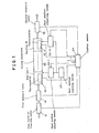
- Reference numeral 10 represents a drying apparatus comprising a cylindrical rotor having a plurality of heater means (not shown) which are independent each other and arranged in a raw material feeding direction.
- the rotor of the drying apparatus may be deemed as being divided into a plurality of drying sections 1 to N corresponding to respective heating means.
- Reference numerals 12 and 14 represent a raw materials flow rate meter and a first moisture meter respectively. The flow rate meter 12 and the first moisture meter 14 are disposed outside the entrance of the drying machine 10 for determining the flow rate and the moisture rate of the raw material charged into the drying apparatus 10.
- a second moisture meter 16 is disposed outside the exit of the drying apparatus 10 for determining the moisture rate of the raw material which has been dried by the drying apparatus 10.
- Thermometers 18-1 to 18-N are provided at the drying sections 1 to N for determining the temperature thereof.
- Reference numeral 20 represents means for supplying heat medium for the purpose of drying which means are connected with the heater means in each section of the drying apparatus.
- the heat medium is supplied in the form of steam in this embodiment.
- Heat medium adjusting means 22-1 to 22-N which are disposed between the heat medium supplying means 20 and the heater means in each section are adapted to adjust the supply of the heat medium to each heater means in the drying sections 1 to N from the heat medium supply means 20 under the control of the control means 24 which will be described hereafter.
- the heater means comprises heating pipes and the heat medium adjusting means 22-1 to 22-N comprise diaphragm valves if the steam is supplied as a heat medium as described above.
- the cylindrical rotor which forms the drying apparatus is tilted so that the entrance is slightly higher.
- the rotor serves to move the raw material which has been charged into the entrance thereof toward the exit and to dry the raw material into a given moisture rate and to discharge it from the exit.
- the control means 24 comprises an electronic computor such as microcomputor.
- the control means 24 receives signals from the raw material flow rate meter 12, the first moisture meter 14, the second moisture meter 16 and thermometers 18-1 to 18-N.
- the control means 24 controls the heat medium adjusting means 22-1 to 22-N by arithmetically processing the signals in accordance with a predetermined program. In other words,the control means 24 generates control signals for opening or closing the diaphragm valves.
- the outline of the structure will be described with reference to Fig. 2.
- reference numeral 241 represents a central processing unit (hereinafter referred to as CPU) which carries out control of jobs which are executed in accordance with a program, arithmetic processing which is necessary in the execution of jobs and control of other devices and management of reception and feeding of the data required for this control.
- CPU central processing unit
- a memory device 242 comprises a read only memory 242a (hereafter referred to as ROM) which stores a program for fixed jobs which the computor executes and a read and write memory 242b (hereafter referred to as RAM) which stores constants required for program, operation results and input information.
- ROM read only memory
- RAM read and write memory
- a process input/output device 243 comprises a multiplexer 243a (hereinafter referred to as MX) which subsequently switches the analog input signals from the raw material flow rate meter.12, the first moisture meter 14, the second moisture meter 16 and the thermometers 22-1 to 22-N, an analog to digital convertor 243B (hereafter referred to as A/D C) which converts the signals from the multiplexer 243a into analog signals which may be processed by the computor and digital to analog convertor 243c (hereafter referred to as D/A C) which converts the digital information obtained by arithmetic processing in the computor into an analog output for actuating the diaphragm valves 22-1 to 22-N.
- MX multiplexer 243a
- A/D C analog to digital convertor
- D/A C digital to analog convertor
- An input/output device 244 comprises a serial interface 244a which provides video information and input data to a CRT display 26 and receives and feeds the data from and to the computor when the data is printed out by a printer 27 and a keyboard input device 244b which transforms the data from a keyboard 28 operated for storing constants by an operator and transmits them to CPC 241.
- Reference numeral 245 represents an data bus through which various data are received and fed among the afore-mentioned devices.
- control device 24 The temperature control by the control device 24 will be described in detail with reference to Fig. 3 and the following figures.
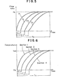
- L 1 , L 2 and L 3 represent the time it takes for the raw material to pass the length between the drying apparatus entrance and the section 2, the length between the drying apparatus entrance and the section 3 and the length between the drying apparatus entrance and the section 4 respectively.
- Ts represents a time unitl the flow rate at each section reaches at the steady flow rate F 0 which is referred to as setting time.
- the flow rate curves F 1 , F 2 , F 3 and F 4 are approximated by omitting L 1 , L 2 and L 3 as follows;
- i 1 to 4
- Tai represents flow rate characteristics constant and s a Laplacian operator.
- the temperature T AO at each section for making the moisture at the exit of the driving apparatus to a constant value under the condition at which F 1 to F 4 reach at a constant flow rate F O after the passage of the period T s may be represented as follows; wherein w 1 represents a moisture rate of the raw material which is obtained from the first moisture meter 14 in Fig. 1.
- the constant flow rate F O is obtained by the raw material flow rate meter 12.
- a, B and ⁇ represent operation parameters.
- a target moisture rate may be obtained at the exit of the drying apparatus immediately after rise-up of the raw material by raising the temperature at each section to T AO represented by the.formula (2) by tracking the curves in Fig. 6 which are similar to those in Fig. 5.
- the ⁇ T Ai (s) is represented as follows; wherein represents a Laplacian transformation operation.
- the temperature response curves at each section change as shown in Fig. 7 when the target value of the temperature at each drying section is stepwise changed. If the target value, thermal transfer characteristics of temperature response among sections and the temperature of the section are represented as T sv (s), G(s) and T A (s) respectively by using Laplacian operator the following relation is established.
- the transfer characteristics G i (s) of each section is represented from the Fig. 7 as follows: wherein T ⁇ i represents a constant of the thermal response characteristics at each sections. Dead time is omitted from the formula (5).
- the preset temperature T * SETi for providing the optimum drying temperature T A at each drying section is represented by the formulae (6), (7) and (8).
- the formula (8) may be obtained by reverse-transforming Tsv(s) which is obtained by putting the above formulae (3) and (5) into the formula (4).
- a bias temperature T cl is preliminarily preset at an interval t 0 to t 1 before the reaching of the raw material as shown in Fig. 9 in order to raise the temperature of the drying section 1 at the time then the raw material reaches at the entrance of the drying apparatus 10 by correcting the thermal response dead time T in rise-up of the temperature at the drying section, which has been described hereabove.
- bias temperatures T c2 , T c3 and T c4 are preliminalily preset between intervals t 2 to t 3 , t 4 to t 5 , t 6 to t 7 with respect to the sections 2 to 4 respectively.
- preset temperatures T * SET 1 , T * SET 2 and T * SET 3 which are obtained by the above-mentioned formula 8 are preset for the intervals t 1 to t 9 , t 3 to t 9 , and t 5 to t 9 respectively in Fig. 9.
- a preset temperature T * SET 4 by the formula 8 is preset only the interval t 7 to t 8 in connection with the section 4. Other temperature presenting is accomplished for the time T8 and following time.
- the moisture rate of the dried raw material is sequentially measured by the second moisture meter 16 at the output side of the drying apparatus 10.
- the drying temperature is controlled so that the measured signal W2 becomes a target moisture rate w *.
- Such control is a feedback control. Since the control is carried out while measuring a true moisture rate, the target moisture rate may be assured.
- the temperature presetting at each section depends upon the forecast method in which a target moisture rate may be obtained upon basis of a model formula in which the flow rate time constant characteristics and then thermal response characteristics etc. are approximated.
- the errors in the model formula and other disturberance are of course involved so that there is a possibility that the moisture rate of the dried raw material becomes a target moisture rate. It is therefore an object of such control to correct the errors.
- Temperature T AO is preset after a time t 9 in accordance with the formula (2) in connection with the sections 1 to 3. This control is carried out in a steady state and referred to as feed forward control. Feed back control is continued in the section 4.
- a valve opening signal m i is obtained by carrying out the adjustment operation of the following formula (9), that is, proportion, integration and differential (PID) operation wherein K p , T 1 and T 0 represent operation parameters referred to as proportional gain, differential time and integration time repectively and T i represents temperature measuring signals from the thermometers 18-1 to 18-4.
- PID proportion, integration and differential
- the valves corresponding to the sections 1 to 4 is opened or closed at an opening which is obtained by the above formula (9) and the valve corresponsing to the section 4 is opened or closed at an opening obtained in accordance with the formula (9) by a cascade control in which Tsv i is preset by a target temperature signal obtained by the above formula (10). By doing so, the moisture rate at the rise-up of the raw material may be quickly changed to a target value soon.
- Ta l , Ta 2 , Ta 3 and Ta 4 of the flow rate characteristics are determined by assumption of the results of a fundamental experiment upon basis of the constant Ta 4 of the flow rate characteristics F 4 of Fig. 5.
- Ta l , Ta 2 and T ⁇ 3 are obtained by multiplying Ta 4 with a factor.
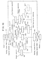
- Fig. 10 is a flow chart showing a program for the afore-mentioned control which the control means 24 executes.
- the heating means No. is set to 1 at step Sl. That is, this setting appoints the control corresponding to the section 1.
- data are read out by addressing the RAM (represented as 242b in Fig. 2) which stores the constants relating to the control of the heating means No. 1 at step S2.
- the program then goes to step 3 at which it determines what control state is.
- the control state used herein includes three controls I to III which begin with the detection of the raw material as shown in Fig. 11.
- the term T R until a bias temperature T ci is preset since the detection of the raw material is defined as state I.
- a bias temperature preset term T s to T R is defined as state II and a term after the completion of the state II is defined as state III. Since the determination at step S3 just after start is state I, the program then proceeds to step S4. At step S4, it is determined whether or not the time after start is larger than T R .
- the time T 1 is represented by the content of the counter which counts 1 per one second since the . detection of the raw material.
- the temperature preset value T * SET is set to 0 at step S5.
- the program then goes to step S6 at which the heating means No. is added with 1 so that the heating means No is changed to 2. It is determined whether or not the.heating means No is larger than 5 at next step S7. Since the result of determination is no, the program returns to step S2. Data is read out by addressing the RAM which stores the constants relating to the control of the heating means NO. 2 at step S2.
- the program goes to step S6 through the steps S3, S4 and S5.
- the heating means No. is changed to 3 at step S6.
- the program then goes to step S6 again through the steps S7, S2, S3,'S4 and S5.
- the heating means No. is changed to 4 at step S6.
- step S6 The program returns to step S6 again through steps S7, S2, S3, S4 and S5.
- the heating means No. is changed to 5.
- step S7 The result of the determination at step S7 is yes, the program returns to start. However the restart is waited until one second has passed since the previous start.
- the program is restarted after the passage of one second and goes to step S7 through the afore-mentioned steps Sl, S2, S3, S4, S5 and 56.
- the jobs of steps S2 to S6 are repeated as is similar to afore-mentioned case until the heating means No. becomes 5.
- the program returns to start.
- step S4 If the T Rl of the heating means No. 1 is assumed to be 8 seconds the above-mentioned jobs would repeated 8 times.
- step S8 The control state of heating means No. 1 is set to state II. Then the program goes to step S6 at which the heating means No. is set to 2. Thereafter the program goes to step S4 through steps S2 and S3.
- the program is then restarted and the heating means No. is set to 1 at step Sl.
- the determination on the control state is carried out at next step S2. Since the result of determination is started II, the program will go to step S9 at which determination whether T>T S or not is carried out. Since the determination result is No, the temperature preset value T * SET 1 is set to a bias temperature T at next step S10.
- step S6 Thereafter the heating means No. is set to 2 at step S6.
- the program will return to step S6 through steps S7, S2, S3, S4 and S5 until the.heating means No. is changed to 5. If the determination results is yes at next step 7, the program will return to start.
- loop job is carried out via the steps Sl, S2, S3, S9, S10, S6 and S7 as to the heating means NO. and the loop job is carried out via the steps S2, S3, S4, S5, S6 and S7 as to the heating means Nos. 2, 3 and 4.
- step S9 the determination result would be No at step S9 and the program will go to step Sll at which the control state of the heating means No. 1 is set to state III. Thereafter the program will go to step S12 at which initialization of RAM which stores data is carried out so that the data on the raw material flow rate F 0 and the moisture rate ⁇ 1 collected before by a dead time T become initial data for control. Then the program will go to the step S7 via the step S6. The loop job of steps S2 to S7 as to heating means Nos. 2 to 4 until the heating means No. becomes 5. When the heating means No. becomes 5, the program will return to START.
- the heating means No. is set to 1 at step Sl again.
- the program will then go to step S3 via step S2. Determination on control state is carried out at step S2. Since the determiantion result is state III, the program will go to step 13 at which feed forward operation shown in the formula (2) is carried out upon basis of the data which have been initialized at the step 12 and constants so that the final desired or target value T AO is calculated.
- the program then goes to step 14 at which pattern operation shown in the formula (8) is carried out so that T*SET 1 is set.
- the program will go to step S7 via step S6 after the operation at step S14.
- Steps S15 to S17 represented by dotted line in Fig. 10 are provided for carrying out feed back control of the heating means No.4. Determination whether or not the heating means No. is equal to 4 is carried out at step S15. Determination whether or not Tl>TB at step S16 wherein T B is a time when feed back control begins. Feed back control is accomplished at step S17.
- the process of the present invention is carried out at a cut tobacco leaves drying appratus under conditions of 12.5% wB of target moisture rate at the exit and not higher than 11.5% wB of abnormal moisture rate, the cut tobacco having an abnormal moisture rate can be suppressed to a remarkably low yield as 5 kg at a total amount at 6000 kg/h of flow rate of the raw material. Furthermore the control of moisture rate may be stably carried out.
- feed back control is carried out at only final section in the above-mentioned embodiment, the same effect may be obtained by carrying out feed back control at other desired sections.
- the temperature of the drying apparatus when the raw material is charged into the drying apparatus is controlled according to the raw material flow rate characteristics and the compensation for the thermal response dead time by application of bias temperature and feed back control based on the moisture rate of the dried tobacco is carried out.
- the production of unqualified product may be minimized by changing the moisture rate of the dried product at the-rise-up time of drying operation of the drying apparatus to a target value as soon as possible.
Landscapes
- Engineering & Computer Science (AREA)
- Mechanical Engineering (AREA)
- General Engineering & Computer Science (AREA)
- Drying Of Solid Materials (AREA)
Applications Claiming Priority (2)
| Application Number | Priority Date | Filing Date | Title |
|---|---|---|---|
| JP58227024A JPS60120182A (ja) | 1983-12-02 | 1983-12-02 | 乾燥機の温度制御方法 |
| JP227024/83 | 1983-12-02 |
Publications (3)
| Publication Number | Publication Date |
|---|---|
| EP0146826A2 true EP0146826A2 (fr) | 1985-07-03 |
| EP0146826A3 EP0146826A3 (en) | 1986-10-01 |
| EP0146826B1 EP0146826B1 (fr) | 1990-09-05 |
Family
ID=16854315
Family Applications (1)
| Application Number | Title | Priority Date | Filing Date |
|---|---|---|---|
| EP84114593A Expired EP0146826B1 (fr) | 1983-12-02 | 1984-11-30 | Procédé de la régulation de la température d'un appareil de séchage |
Country Status (4)
| Country | Link |
|---|---|
| US (1) | US4660298A (fr) |
| EP (1) | EP0146826B1 (fr) |
| JP (1) | JPS60120182A (fr) |
| DE (1) | DE3483143D1 (fr) |
Cited By (3)
| Publication number | Priority date | Publication date | Assignee | Title |
|---|---|---|---|---|
| EP0165578A3 (en) * | 1984-06-21 | 1987-07-29 | Japan Tobacco Inc. | Process for the temperature control of a drying apparatus for tabacco leaves |
| EP0580127A1 (fr) * | 1992-07-21 | 1994-01-26 | Mitsubishi Chemical Corporation | Procédé et dispositif de séchage de poudre et matériau granuleux |
| US9897508B2 (en) | 2010-12-30 | 2018-02-20 | Eaton Corporation | Leak detection system |
Families Citing this family (10)
| Publication number | Priority date | Publication date | Assignee | Title |
|---|---|---|---|---|
| US4795871A (en) * | 1986-10-20 | 1989-01-03 | Micro Dry, Inc. | Method and apparatus for heating and drying fabrics in a drying chamber having dryness sensing devices |
| US5323546A (en) * | 1989-02-10 | 1994-06-28 | Eastman Kodak Company | Method of drying photographic materials |
| JP2810885B2 (ja) * | 1989-08-01 | 1998-10-15 | 三菱化学株式会社 | 粉粒体材料のオンライン乾燥制御方法及びこの方法を使用したオンライン乾燥制御システム |
| JP2863860B2 (ja) * | 1989-08-01 | 1999-03-03 | 三菱化学株式会社 | 粉粒体材料のオンライン水分管理システム |
| US5570521A (en) * | 1990-11-26 | 1996-11-05 | Ffi Corporation | Control system for a grain dryer and probe mounting apparatus therefor |
| AU9125491A (en) * | 1990-11-26 | 1992-06-25 | Ffi Corporation | Control system for a grain dryer and probe mounting arrangement therefor |
| US5487225A (en) * | 1994-11-14 | 1996-01-30 | The Conair Group, Inc. | Apparatus and method for controlled drying of plastic pellets |
| US6787743B2 (en) * | 2002-01-04 | 2004-09-07 | Pao-Hsien Fang | Apparatus for the production of ginkgo leaf tea |
| CN100434850C (zh) * | 2005-08-26 | 2008-11-19 | 卢英林 | 干燥设备自动控制物料湿度的方法 |
| US8528385B2 (en) | 2010-12-30 | 2013-09-10 | Eaton Corporation | Leak detection system |
Family Cites Families (13)
| Publication number | Priority date | Publication date | Assignee | Title |
|---|---|---|---|---|
| US2644681A (en) * | 1947-04-08 | 1953-07-07 | Jabez Burns & Sons Inc | Apparatus for roasting vegetable materials |
| US3204341A (en) * | 1961-11-27 | 1965-09-07 | Ashland Oil Inc | Process and apparatus for drying wet particulate material to a desired moisture content |
| US3219329A (en) * | 1962-04-09 | 1965-11-23 | Phillips Petroleum Co | Radiant heat drying method and apparatus |
| US3350790A (en) * | 1965-07-12 | 1967-11-07 | Ashland Oil Inc | Temperature control system for rotary dryers |
| GB1100017A (en) * | 1965-07-13 | 1968-01-24 | Korber Kurt | Apparatus for drying tobacco |
| NL6802583A (fr) * | 1967-02-25 | 1968-08-26 | ||
| US3518775A (en) * | 1968-11-25 | 1970-07-07 | Eastman Kodak Co | Moisture control system |
| DE2904308C2 (de) * | 1979-02-05 | 1986-10-23 | Hauni-Werke Körber & Co KG, 2050 Hamburg | Verfahren und Anordnung zum Trocknen von Tabak |
| ZA756260B (en) * | 1975-10-02 | 1977-05-25 | Tobacco Res & Dev | Drying method and apparatus |
| DE2724037A1 (de) * | 1977-05-27 | 1978-12-07 | Hauni Werke Koerber & Co Kg | Vorrichtung zum trocknen eines kontinuierlich gefoerderten tabakstromes |
| US4170073A (en) * | 1977-12-01 | 1979-10-09 | Kay-Ray, Inc. | Wide dynamic range multi-zone drying method and apparatus for controlling product moisture |
| IT1151299B (it) * | 1981-07-07 | 1986-12-17 | Hauni Werke Koerber & Co Kg | Mezzi di comando per un essiccatore a tamburo |
| US4498864A (en) * | 1982-12-10 | 1985-02-12 | Techmark Corporation | Method and apparatus for uniformly drying moving webs |
-
1983
- 1983-12-02 JP JP58227024A patent/JPS60120182A/ja active Granted
-
1984
- 1984-11-30 US US06/676,640 patent/US4660298A/en not_active Expired - Lifetime
- 1984-11-30 EP EP84114593A patent/EP0146826B1/fr not_active Expired
- 1984-11-30 DE DE8484114593T patent/DE3483143D1/de not_active Expired - Fee Related
Cited By (4)
| Publication number | Priority date | Publication date | Assignee | Title |
|---|---|---|---|---|
| EP0165578A3 (en) * | 1984-06-21 | 1987-07-29 | Japan Tobacco Inc. | Process for the temperature control of a drying apparatus for tabacco leaves |
| EP0580127A1 (fr) * | 1992-07-21 | 1994-01-26 | Mitsubishi Chemical Corporation | Procédé et dispositif de séchage de poudre et matériau granuleux |
| US5341577A (en) * | 1992-07-21 | 1994-08-30 | Mitsubishi Kasei Corporation | Drying method of and drying apparatus for powder and granular material |
| US9897508B2 (en) | 2010-12-30 | 2018-02-20 | Eaton Corporation | Leak detection system |
Also Published As
| Publication number | Publication date |
|---|---|
| JPS6319792B2 (fr) | 1988-04-25 |
| JPS60120182A (ja) | 1985-06-27 |
| EP0146826A3 (en) | 1986-10-01 |
| DE3483143D1 (de) | 1990-10-11 |
| EP0146826B1 (fr) | 1990-09-05 |
| US4660298A (en) | 1987-04-28 |
Similar Documents
| Publication | Publication Date | Title |
|---|---|---|
| EP0165578B1 (fr) | Procédé pour le contrôle de la température d'un appareil de séchage pour des feuilles de tabac | |
| EP0146826A2 (fr) | Procédé de la régulation de la température d'un appareil de séchage | |
| US4197070A (en) | Apparatus for controlling a plastic extruder | |
| US6502581B2 (en) | Method and device for regulating the output humidity of tobacco | |
| US4290986A (en) | Method for controlling a plastic extruder | |
| AU595745B2 (en) | Method and apparatus for extruding a food product | |
| US3694636A (en) | Digital computer process control with operational learning procedure | |
| US5832990A (en) | Automatic temperature control method and apparatus for an automotive vehicle | |
| US5886533A (en) | Controlling water addition to grains using feedback to match a target microwave value | |
| US5170341A (en) | Adaptive controller in a process control system and a method therefor | |
| JP2002542810A (ja) | 練り粉製品製造装置内の工程管理と工程監視の適正化方法と装置 | |
| MXPA97006051A (es) | Metodo y dispositivo para controlar la adicion de agua a granos | |
| US4587743A (en) | Method of controlling temperature of drying machine | |
| JP2783124B2 (ja) | 熱延鋼材の温度制御方法 | |
| US6418638B1 (en) | Dryer control system | |
| JPH09239423A (ja) | 棒鋼類圧延設備における水冷制御方法 | |
| JPH0636931B2 (ja) | 線材、棒材の圧延、冷却における温度制御方法 | |
| JP3251541B2 (ja) | プロセスの自動制御装置 | |
| JPS59198928A (ja) | パン生地の混捏制御方法および装置 | |
| JPH08300024A (ja) | 熱間圧延における板幅制御方法 | |
| SU1142713A1 (ru) | Способ автоматического управлени процессом сушки | |
| JPH0759722B2 (ja) | 先にガス加熱されたスラブの後続の誘導加熱時の誘導加熱制御方法 | |
| KR100250760B1 (ko) | 연속식로안의 강철재료의 처리상태를 제어하는 방법 및 이의 제어장치 | |
| SU958559A1 (ru) | Система автоматического управлени температурным режимом варки сульфатной целлюлозы | |
| RU2030994C1 (ru) | Способ управления процессом термообработки железобетонных изделий |
Legal Events
| Date | Code | Title | Description |
|---|---|---|---|
| PUAI | Public reference made under article 153(3) epc to a published international application that has entered the european phase |
Free format text: ORIGINAL CODE: 0009012 |
|
| AK | Designated contracting states |
Designated state(s): DE GB IT |
|
| 17P | Request for examination filed |
Effective date: 19850903 |
|
| RAP1 | Party data changed (applicant data changed or rights of an application transferred) |
Owner name: JAPAN TOBACCO INC. |
|
| PUAL | Search report despatched |
Free format text: ORIGINAL CODE: 0009013 |
|
| RHK1 | Main classification (correction) |
Ipc: G05D 22/00 |
|
| AK | Designated contracting states |
Kind code of ref document: A3 Designated state(s): DE GB IT |
|
| 17Q | First examination report despatched |
Effective date: 19880902 |
|
| GRAA | (expected) grant |
Free format text: ORIGINAL CODE: 0009210 |
|
| AK | Designated contracting states |
Kind code of ref document: B1 Designated state(s): DE GB IT |
|
| ITF | It: translation for a ep patent filed | ||
| REF | Corresponds to: |
Ref document number: 3483143 Country of ref document: DE Date of ref document: 19901011 |
|
| PLBE | No opposition filed within time limit |
Free format text: ORIGINAL CODE: 0009261 |
|
| STAA | Information on the status of an ep patent application or granted ep patent |
Free format text: STATUS: NO OPPOSITION FILED WITHIN TIME LIMIT |
|
| 26N | No opposition filed | ||
| ITTA | It: last paid annual fee | ||
| PGFP | Annual fee paid to national office [announced via postgrant information from national office to epo] |
Ref country code: GB Payment date: 20000906 Year of fee payment: 17 |
|
| PGFP | Annual fee paid to national office [announced via postgrant information from national office to epo] |
Ref country code: DE Payment date: 20010118 Year of fee payment: 17 |
|
| PG25 | Lapsed in a contracting state [announced via postgrant information from national office to epo] |
Ref country code: GB Free format text: LAPSE BECAUSE OF NON-PAYMENT OF DUE FEES Effective date: 20011130 |
|
| REG | Reference to a national code |
Ref country code: GB Ref legal event code: IF02 |
|
| PG25 | Lapsed in a contracting state [announced via postgrant information from national office to epo] |
Ref country code: DE Free format text: LAPSE BECAUSE OF NON-PAYMENT OF DUE FEES Effective date: 20020702 |
|
| GBPC | Gb: european patent ceased through non-payment of renewal fee |
Effective date: 20011130 |