EP0146869A2 - Dispositif d'empilage intermédiaire de matière à découper - Google Patents
Dispositif d'empilage intermédiaire de matière à découper Download PDFInfo
- Publication number
- EP0146869A2 EP0146869A2 EP84115166A EP84115166A EP0146869A2 EP 0146869 A2 EP0146869 A2 EP 0146869A2 EP 84115166 A EP84115166 A EP 84115166A EP 84115166 A EP84115166 A EP 84115166A EP 0146869 A2 EP0146869 A2 EP 0146869A2
- Authority
- EP
- European Patent Office
- Prior art keywords
- board
- stack
- stops
- work
- boards
- Prior art date
- Legal status (The legal status is an assumption and is not a legal conclusion. Google has not performed a legal analysis and makes no representation as to the accuracy of the status listed.)
- Granted
Links
- 238000005520 cutting process Methods 0.000 title claims description 12
- 238000006073 displacement reaction Methods 0.000 claims description 6
- 238000012432 intermediate storage Methods 0.000 abstract description 2
- 238000003780 insertion Methods 0.000 description 1
- 230000037431 insertion Effects 0.000 description 1
- 238000000034 method Methods 0.000 description 1
- 230000000284 resting effect Effects 0.000 description 1
- 238000000926 separation method Methods 0.000 description 1
Images
Classifications
-
- B—PERFORMING OPERATIONS; TRANSPORTING
- B65—CONVEYING; PACKING; STORING; HANDLING THIN OR FILAMENTARY MATERIAL
- B65H—HANDLING THIN OR FILAMENTARY MATERIAL, e.g. SHEETS, WEBS, CABLES
- B65H33/00—Forming counted batches in delivery pile or stream of articles
- B65H33/16—Forming counted batches in delivery pile or stream of articles by depositing articles in batches on moving supports
- B65H33/18—Forming counted batches in delivery pile or stream of articles by depositing articles in batches on moving supports with separators between adjacent batches
-
- Y—GENERAL TAGGING OF NEW TECHNOLOGICAL DEVELOPMENTS; GENERAL TAGGING OF CROSS-SECTIONAL TECHNOLOGIES SPANNING OVER SEVERAL SECTIONS OF THE IPC; TECHNICAL SUBJECTS COVERED BY FORMER USPC CROSS-REFERENCE ART COLLECTIONS [XRACs] AND DIGESTS
- Y10—TECHNICAL SUBJECTS COVERED BY FORMER USPC
- Y10S—TECHNICAL SUBJECTS COVERED BY FORMER USPC CROSS-REFERENCE ART COLLECTIONS [XRACs] AND DIGESTS
- Y10S414/00—Material or article handling
- Y10S414/10—Associated with forming or dispersing groups of intersupporting articles, e.g. stacking patterns
- Y10S414/101—Associated with forming or dispersing groups of intersupporting articles, e.g. stacking patterns with article-supporting fluid cushion
-
- Y—GENERAL TAGGING OF NEW TECHNOLOGICAL DEVELOPMENTS; GENERAL TAGGING OF CROSS-SECTIONAL TECHNOLOGIES SPANNING OVER SEVERAL SECTIONS OF THE IPC; TECHNICAL SUBJECTS COVERED BY FORMER USPC CROSS-REFERENCE ART COLLECTIONS [XRACs] AND DIGESTS
- Y10—TECHNICAL SUBJECTS COVERED BY FORMER USPC
- Y10S—TECHNICAL SUBJECTS COVERED BY FORMER USPC CROSS-REFERENCE ART COLLECTIONS [XRACs] AND DIGESTS
- Y10S414/00—Material or article handling
- Y10S414/10—Associated with forming or dispersing groups of intersupporting articles, e.g. stacking patterns
- Y10S414/112—Group formed or dispensed by reversible apparatus
Definitions
- the invention relates to a device for intermediate stacking of material to be cut, in which the material to be cut is fed from the work table to a first work station, in particular a vibrating table, to a stack lift, on which the material to be cut is stored with the intermediate storage of boards to form partial stacks and from there to the work table of a second work station , in particular a cutting table of a cutting machine.
- Such a device is known from DE-PS 1 244 711.
- the material to be cut is shaken on a vibrating table before the cutting process, in order to thereby align the individual sheets precisely with one another.
- the material to be cut is stacked on a stack lift.
- the partial stacks lie one above the other on the stack lift, boards being arranged between the individual partial stacks.
- the partial stacks are shifted from the vibrating table to the boards or from the boards to the cutting table in a simple manner in that the boards are designed as air boards, i.e. they are provided with an air supply and, on the surface facing the stacking part, are provided with air outlet nozzles.
- the object of the invention is to provide a device with which it is possible to stack material to be cut without the partial stacks being shifted during loading or unloading.
- movable stops are arranged below the level of the support surfaces of the work tables, the stops being in the retracted position outside the displacement formed when the boards are raised and lowered, engaging in the extended position in the extended position and when a board is placed on the board on the extended stops the support surface of the board forms a level with the support surfaces - the work tables.
- the stack lift When loading the stack lift, it is lowered to such an extent that a transport pallet lying thereon and / or partial stacks already deposited are located below the stops. Then the stops are moved to the extended position and the board is placed on dirs p . The stops hold the board in this position, in which the bearing surface of the board forms a plane with the bearing surface of the work tables. The partial stack to be put down is pushed onto the board and then the stack lift is raised so that the top board with the now placed partial stack relieves the stops.
- the stops are moved to their retracted position, ie they are outside of when lifting and the boards formed cubic capacity, the stack lift is lowered so that the surface of the last stacked part of the stack is below the stops and forms an intermediate space to the underside of the board to be placed later. Finally, the attacks to record the next board and a further stack of leils are moved into the extended position.
- the stack lift When processing the partial stack, the stack lift is raised so far that the stops can be moved under the board carrying the uppermost partial stack.
- the stack lift is lowered to such an extent that the top board rests on the stops and there is a gap between the underside of the top board and the surface of the sub-stack provided underneath, or in the final stage of the workflow there is a gap between the underside of the top air board and the surface of the Transport pallet forms.
- the prepared partial stack is then fed to the second work station, the board is removed and the stops are moved into the retracted position.
- the next partial stack is then raised by the stack lift.
- the stops according to the invention thus have the task of ensuring the horizontal position of the board lying on them and the flushness of the contact surface of the board with the contact surfaces of the work tables. While usually the stack lift takes over the bearing function for the partial stack and the intervening boards, this is Tra g efunktion for the top board and the partial stack thereon perceived by the attacks. The separation of the uppermost board from the remaining stack during loading or unloading prevents the partial stack lying under the uppermost board from shifting.
- the stops can be attached to both the workstations and the stack lift.
- the stops are expediently designed as flaps. one end of which is at the bottom of the work tables Workstations are pivotally attached and desse Serves the end of the edition of the board. If the flaps are arranged on the underside of the worktables, the stacking shirt is particularly space-saving. To pivot the flap should also on the lower Power elements, in particular hydraulic power cylinders, can be arranged on the side of the work tables.
- stops are also advisable to arrange the stops not on the underside of the work tables, but rather on a swivel.
- thorn-like projections could extend under the board in the extended position or engage in corresponding recesses in the board and thus hold the board in a flush position with the work tables.
- the displacement of the extensions from the retracted to the extended position and back would also be effected by force elements.
- the boards advantageously have supports on their underside, the length of the individual supports being the same but greater than the height of the sub-stack lying under the board.
- the use of such boards with supports is indicated when the individual partial stacks consist of lightweight, high-quality fin sheets. In this case, the load of all partial stacks does not rest on the lower partial stack, but the boards are supported on the other boards.
- the boards In order to ensure that the stack of cables can be easily pushed over, the boards should be designed as air boards with air intake and exhaust openings.
- the stacking lift advantageously has wheels drive on. Still while with extended attacks The partial stack lying on the board is moved to the next work station, or while partial stacks are being transported from one work station over the board to the other work station, the stack lift can move the work area leave and get new material.
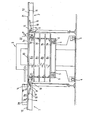
- FIG. 1 shows a longitudinal section through the device.
- a stack lift 3 Between a partly only shown vibrating table 1 and also a partly shown cutting table of a paper cutting machine there is a stack lift 3.
- This has wheels 4 for moving on its underside.
- the partially raised lifting fork 5 of the stack lift 4 passes through a pallet 6 on which the material to be cut is stored to form partial stacks 8a to 8d with the interposition of air boards 7a to 7e.
- the arrangement of the flaps on the undersides 9 and 11 and the dimensions of the flaps with the am Flap end arranged supports 18 is such that in the swung-out state of the flaps 13, as shown in the figure, the air board 7e can be placed on the supports 18, the support surface 19 forming a plane with the support surfaces 20 and 21 of the worktops 10 and 12 .
- the air inlet opening of the air board 7e which is not shown in any more detail, is connected to an air bell 22 which is shown schematically. This causes an air flow into the board 7e and then through at the top Read the air outlet openings arranged on the board.
- the air film forming above the air board 7e makes it easier to push the partial stack 8e over from the support surface 20 to the air board 7e.
- the lifting fork 5 of the stack lift 3 is moved so far down that A space remains between the underside of the air board 7e and the surface of the partial stack 8d. This ensures that the upper individual sheets of the partial stack 8d cannot be moved during the displacement of the partial stack 8e onto the air board 7e.
- the lifting fork 5 of the stack lift 3 is raised slightly in order to relieve the flaps 13.
- the air board 7e comes to a standstill with its four supports 23 on the air board 7d, whereby it does not touch the partial stack 8d located on the air board 7d.
- the remaining air boards 7a to 7d do not have such supports 23, the board 7b lies directly on the stack 8a, the board 7c directly on the stack 8b and the board 7d directly on the stack 8c.
Landscapes
- Pile Receivers (AREA)
- Sheets, Magazines, And Separation Thereof (AREA)
- Details Of Cutting Devices (AREA)
- Stacking Of Articles And Auxiliary Devices (AREA)
- Warehouses Or Storage Devices (AREA)
- Collation Of Sheets And Webs (AREA)
- Forming Counted Batches (AREA)
Priority Applications (1)
| Application Number | Priority Date | Filing Date | Title |
|---|---|---|---|
| AT84115166T ATE27439T1 (de) | 1983-12-14 | 1984-12-11 | Vorrichtung zum zwischenstapeln von schneidegut. |
Applications Claiming Priority (2)
| Application Number | Priority Date | Filing Date | Title |
|---|---|---|---|
| DE19838335816U DE8335816U1 (de) | 1983-12-14 | 1983-12-14 | Vorrichtung zum zwischenstapeln von schneidgut |
| DE8335816U | 1983-12-14 |
Publications (3)
| Publication Number | Publication Date |
|---|---|
| EP0146869A2 true EP0146869A2 (fr) | 1985-07-03 |
| EP0146869A3 EP0146869A3 (en) | 1985-07-31 |
| EP0146869B1 EP0146869B1 (fr) | 1987-05-27 |
Family
ID=6759824
Family Applications (1)
| Application Number | Title | Priority Date | Filing Date |
|---|---|---|---|
| EP84115166A Expired EP0146869B1 (fr) | 1983-12-14 | 1984-12-11 | Dispositif d'empilage intermédiaire de matière à découper |
Country Status (6)
| Country | Link |
|---|---|
| US (1) | US4613267A (fr) |
| EP (1) | EP0146869B1 (fr) |
| JP (2) | JPS60144276A (fr) |
| AT (1) | ATE27439T1 (fr) |
| DE (2) | DE8335816U1 (fr) |
| ES (1) | ES8603785A1 (fr) |
Cited By (2)
| Publication number | Priority date | Publication date | Assignee | Title |
|---|---|---|---|---|
| FR2587311A1 (fr) * | 1985-09-18 | 1987-03-20 | Schauman | Procede et installation de manutention automatique et stockage temporaire de paquets empiles de produits semi-finis en feuilles. |
| EP0652171A1 (fr) * | 1993-10-05 | 1995-05-10 | SEEMI Société d'Etudes d'Equipements de Modernisation Industrielle | Procédé et dispositif pour palettiser des sections tubulaires en papier ou similaires |
Families Citing this family (6)
| Publication number | Priority date | Publication date | Assignee | Title |
|---|---|---|---|---|
| DE3613462A1 (de) * | 1986-04-22 | 1987-10-29 | Wolfgang Mohr | Vorrichtung zum be- und entladen eines stapellifts |
| US5256028A (en) * | 1986-07-23 | 1993-10-26 | Winski Ernest P | Process for handling material |
| DE3914598C2 (de) * | 1989-05-03 | 1994-05-19 | Focke & Co | Verfahren und Vorrichtung zum Abräumen von Gegenständen von einer Unterlage mit hohem Reibungswiderstand |
| DE3940190A1 (de) * | 1989-12-05 | 1991-06-06 | Kolbus Gmbh & Co Kg | Verfahren zum be- und entladen von paletten mit stapeln von flaechigen produkten und einrichtung zur durchfuehrung des verfahrens |
| US5562403A (en) * | 1991-02-11 | 1996-10-08 | Winski; Ernest P. | Load forming apparatus and methods |
| US6305500B1 (en) * | 1999-08-25 | 2001-10-23 | Maxtor Corporation | Material delivery system for clean room-like environments |
Family Cites Families (16)
| Publication number | Priority date | Publication date | Assignee | Title |
|---|---|---|---|---|
| US30742A (en) * | 1860-11-27 | Improvement in ordnance | ||
| US674262A (en) * | 1900-02-21 | 1901-05-14 | Garland H Duncan | Lumber-stacker. |
| US1225523A (en) * | 1915-02-27 | 1917-05-08 | Robert E Surles | Lumber-stacker. |
| US3146897A (en) * | 1962-01-11 | 1964-09-01 | Kalamazoo Paper Company | Paper pile separating and stacking transfer apparatus |
| US3363781A (en) * | 1963-06-14 | 1968-01-16 | Magnetti Enrico | Stacking mechanism |
| DE1244711B (de) * | 1965-06-12 | 1967-07-20 | Rudolf Mohr | Vorrichtung zum Stapeln von Schneidegut und selbsttaetigem Zufuehren an den Arbeitstisch, insbesondere von Papierschneidemaschinen |
| US3398841A (en) * | 1967-02-07 | 1968-08-27 | Mohr Rudolf | Apparatus for stacking material and automatically feeding the material to a worktable of a paper-cutting machine |
| USRE30742E (en) | 1968-02-11 | 1981-09-15 | Wyard Industries, Inc. | Container depalletizing apparatus |
| US3548995A (en) * | 1968-06-13 | 1970-12-22 | Sta Hi Corp | Controlled variable speed stacking device for publication conveyor |
| US3960374A (en) * | 1972-06-15 | 1976-06-01 | Harris-Intertype Corporation | Sheet delivery system |
| US3897877A (en) * | 1973-08-22 | 1975-08-05 | Goldco Industries | Apparatus for positioning and orienting palletized articles |
| CA975813A (en) * | 1974-09-06 | 1975-10-07 | Theodore E. O'brien | Apparatus for automatically stacking and compressing batts of compressible material |
| JPS5655166U (fr) * | 1979-10-06 | 1981-05-14 | ||
| JPS6011676B2 (ja) * | 1980-04-10 | 1985-03-27 | 小森印刷機械株式会社 | 印刷機排紙部の紙流れ防止装置 |
| JPS5930620B2 (ja) * | 1981-05-21 | 1984-07-27 | 東洋ガラス機械株式会社 | 多重積層容器体からの容器取出移送装置 |
| JPS5811787U (ja) * | 1981-07-15 | 1983-01-25 | 株式会社日立製作所 | 行先表示装置 |
-
1983
- 1983-12-14 DE DE19838335816U patent/DE8335816U1/de not_active Expired
-
1984
- 1984-12-07 JP JP59257741A patent/JPS60144276A/ja active Pending
- 1984-12-10 US US06/679,745 patent/US4613267A/en not_active Expired - Fee Related
- 1984-12-11 AT AT84115166T patent/ATE27439T1/de not_active IP Right Cessation
- 1984-12-11 DE DE8484115166T patent/DE3463921D1/de not_active Expired
- 1984-12-11 EP EP84115166A patent/EP0146869B1/fr not_active Expired
- 1984-12-14 ES ES538622A patent/ES8603785A1/es not_active Expired
-
1991
- 1991-09-27 JP JP1991099454U patent/JP2525234Y2/ja not_active Expired - Lifetime
Cited By (2)
| Publication number | Priority date | Publication date | Assignee | Title |
|---|---|---|---|---|
| FR2587311A1 (fr) * | 1985-09-18 | 1987-03-20 | Schauman | Procede et installation de manutention automatique et stockage temporaire de paquets empiles de produits semi-finis en feuilles. |
| EP0652171A1 (fr) * | 1993-10-05 | 1995-05-10 | SEEMI Société d'Etudes d'Equipements de Modernisation Industrielle | Procédé et dispositif pour palettiser des sections tubulaires en papier ou similaires |
Also Published As
| Publication number | Publication date |
|---|---|
| ES538622A0 (es) | 1986-01-16 |
| EP0146869A3 (en) | 1985-07-31 |
| JPH081281U (ja) | 1996-08-13 |
| ATE27439T1 (de) | 1987-06-15 |
| EP0146869B1 (fr) | 1987-05-27 |
| ES8603785A1 (es) | 1986-01-16 |
| DE3463921D1 (en) | 1987-07-02 |
| US4613267A (en) | 1986-09-23 |
| JPS60144276A (ja) | 1985-07-30 |
| JP2525234Y2 (ja) | 1997-02-05 |
| DE8335816U1 (de) | 1984-04-26 |
Similar Documents
| Publication | Publication Date | Title |
|---|---|---|
| EP0077508B1 (fr) | Procédé et dispositif d'emballage de piles d'objets palettisés | |
| DE10123326C1 (de) | Auslagevorrichtung für eine Bogen verarbeitende Maschine und Verfahren zum Auslegen von Bogen in einer Bogen verarbeitenden Maschine | |
| DE7908192U1 (de) | Stapelvorrichtung | |
| DE10392503T5 (de) | Palette | |
| DE2751489C2 (de) | Vorrichtung zum Wechseln eines Bogenstapels | |
| DE2952624A1 (de) | Vorrichtung zum gruppieren von gegenstaenden in stapelschichten zur beschickung von paletten | |
| DE2547149A1 (de) | Verfahren und vorrichtung zur herstellung von platten oder tafeln aus zellstoff bzw. faser- oder spanwerkstoff | |
| EP0316568A2 (fr) | Dispositif pour enlever des piles de feuilles | |
| EP0146869B1 (fr) | Dispositif d'empilage intermédiaire de matière à découper | |
| DE2942965A1 (de) | Stapeleinrichtung insbesondere fuer druckmaschinen | |
| DE4021676C1 (fr) | ||
| DE3304673C2 (de) | Verfahren zum Wechseln eines Bogenstapels bei ununterbrochener Förderung von Bogen zur Stapelstelle | |
| DE19708125A1 (de) | Stapler | |
| DE2630094C2 (de) | Verfahren zur Trennung und Stapelung von gestanzten Bögen | |
| DE1506511A1 (de) | Vorrichtung und Verfahren zum Transportieren von Platten | |
| DE2626630C2 (de) | Verfahren und Gerät zur Trennung und Stapelung von gestanzten Bögen | |
| DE3820236A1 (de) | Aufgabevorrichtung von aus plattenstapel gebildeten paketen und verfahren zum bereitstellen der pakete auf der aufgabevorrichtung | |
| DE19831640A1 (de) | Mehrweg-Transportbehälter | |
| EP1329401A2 (fr) | Agencement et procédé pour décharger des lots de cahiers pour la formation d'une pile | |
| DE8804182U1 (de) | Tragplatte zum Stapeln von Bogen | |
| EP0191807B1 (fr) | Procede et systeme de changement de palettes | |
| DE3914598C2 (de) | Verfahren und Vorrichtung zum Abräumen von Gegenständen von einer Unterlage mit hohem Reibungswiderstand | |
| EP0945370B1 (fr) | Dispositif de positionnement pour au moins une palette | |
| DE2656116C3 (de) | Vorrichtung zum stapelweisen Ablegen von flexiblen Paneelen auf einem unterhalb eines Endlosförderers angeordneten Stapeltisch | |
| DD244958A1 (de) | Vorrichtung zum halten von senkrechtstehenden gefalteten lagen und pappen mit abschwenkbarem stapelhalter |
Legal Events
| Date | Code | Title | Description |
|---|---|---|---|
| PUAI | Public reference made under article 153(3) epc to a published international application that has entered the european phase |
Free format text: ORIGINAL CODE: 0009012 |
|
| PUAL | Search report despatched |
Free format text: ORIGINAL CODE: 0009013 |
|
| 17P | Request for examination filed |
Effective date: 19841224 |
|
| AK | Designated contracting states |
Designated state(s): AT BE CH DE FR GB IT LI LU NL SE |
|
| ITCL | It: translation for ep claims filed |
Representative=s name: MODIANO & ASSOCIATI S.R.L. |
|
| AK | Designated contracting states |
Designated state(s): AT BE CH DE FR GB IT LI LU NL SE |
|
| EL | Fr: translation of claims filed | ||
| TCNL | Nl: translation of patent claims filed | ||
| 17Q | First examination report despatched |
Effective date: 19860221 |
|
| GRAA | (expected) grant |
Free format text: ORIGINAL CODE: 0009210 |
|
| AK | Designated contracting states |
Kind code of ref document: B1 Designated state(s): AT BE CH DE FR GB IT LI LU NL SE |
|
| REF | Corresponds to: |
Ref document number: 27439 Country of ref document: AT Date of ref document: 19870615 Kind code of ref document: T |
|
| REF | Corresponds to: |
Ref document number: 3463921 Country of ref document: DE Date of ref document: 19870702 |
|
| ET | Fr: translation filed | ||
| ITF | It: translation for a ep patent filed | ||
| PLBE | No opposition filed within time limit |
Free format text: ORIGINAL CODE: 0009261 |
|
| STAA | Information on the status of an ep patent application or granted ep patent |
Free format text: STATUS: NO OPPOSITION FILED WITHIN TIME LIMIT |
|
| 26N | No opposition filed | ||
| REG | Reference to a national code |
Ref country code: CH Ref legal event code: PUE Owner name: ROLF MOHR |
|
| NLS | Nl: assignments of ep-patents |
Owner name: ROLF MOHR EN WOLFGANG MOHR BEIDEN TE HOFHEIM A.D. |
|
| REG | Reference to a national code |
Ref country code: FR Ref legal event code: TP |
|
| ITPR | It: changes in ownership of a european patent |
Owner name: CESSIONE;ROLF MOHR |
|
| REG | Reference to a national code |
Ref country code: GB Ref legal event code: 732 |
|
| ITTA | It: last paid annual fee | ||
| EPTA | Lu: last paid annual fee | ||
| EAL | Se: european patent in force in sweden |
Ref document number: 84115166.5 |
|
| PGFP | Annual fee paid to national office [announced via postgrant information from national office to epo] |
Ref country code: LU Payment date: 19961101 Year of fee payment: 13 |
|
| PGFP | Annual fee paid to national office [announced via postgrant information from national office to epo] |
Ref country code: SE Payment date: 19961125 Year of fee payment: 13 Ref country code: CH Payment date: 19961125 Year of fee payment: 13 |
|
| PGFP | Annual fee paid to national office [announced via postgrant information from national office to epo] |
Ref country code: GB Payment date: 19961126 Year of fee payment: 13 Ref country code: BE Payment date: 19961126 Year of fee payment: 13 |
|
| PGFP | Annual fee paid to national office [announced via postgrant information from national office to epo] |
Ref country code: NL Payment date: 19961127 Year of fee payment: 13 |
|
| PGFP | Annual fee paid to national office [announced via postgrant information from national office to epo] |
Ref country code: FR Payment date: 19961128 Year of fee payment: 13 Ref country code: AT Payment date: 19961128 Year of fee payment: 13 |
|
| PGFP | Annual fee paid to national office [announced via postgrant information from national office to epo] |
Ref country code: DE Payment date: 19961227 Year of fee payment: 13 |
|
| PG25 | Lapsed in a contracting state [announced via postgrant information from national office to epo] |
Ref country code: LU Free format text: LAPSE BECAUSE OF NON-PAYMENT OF DUE FEES Effective date: 19971211 Ref country code: GB Free format text: LAPSE BECAUSE OF NON-PAYMENT OF DUE FEES Effective date: 19971211 Ref country code: AT Free format text: LAPSE BECAUSE OF NON-PAYMENT OF DUE FEES Effective date: 19971211 |
|
| PG25 | Lapsed in a contracting state [announced via postgrant information from national office to epo] |
Ref country code: SE Free format text: LAPSE BECAUSE OF NON-PAYMENT OF DUE FEES Effective date: 19971212 |
|
| PG25 | Lapsed in a contracting state [announced via postgrant information from national office to epo] |
Ref country code: LI Free format text: LAPSE BECAUSE OF NON-PAYMENT OF DUE FEES Effective date: 19971231 Ref country code: FR Free format text: THE PATENT HAS BEEN ANNULLED BY A DECISION OF A NATIONAL AUTHORITY Effective date: 19971231 Ref country code: CH Free format text: LAPSE BECAUSE OF NON-PAYMENT OF DUE FEES Effective date: 19971231 Ref country code: BE Free format text: LAPSE BECAUSE OF NON-PAYMENT OF DUE FEES Effective date: 19971231 |
|
| BERE | Be: lapsed |
Owner name: MOHR ROLF Effective date: 19971231 Owner name: MOHR WOLFGANG Effective date: 19971231 |
|
| PG25 | Lapsed in a contracting state [announced via postgrant information from national office to epo] |
Ref country code: NL Free format text: LAPSE BECAUSE OF NON-PAYMENT OF DUE FEES Effective date: 19980701 |
|
| GBPC | Gb: european patent ceased through non-payment of renewal fee |
Effective date: 19971211 |
|
| REG | Reference to a national code |
Ref country code: CH Ref legal event code: PL |
|
| NLV4 | Nl: lapsed or anulled due to non-payment of the annual fee |
Effective date: 19980701 |
|
| PG25 | Lapsed in a contracting state [announced via postgrant information from national office to epo] |
Ref country code: DE Free format text: LAPSE BECAUSE OF NON-PAYMENT OF DUE FEES Effective date: 19980901 |
|
| EUG | Se: european patent has lapsed |
Ref document number: 84115166.5 |
|
| REG | Reference to a national code |
Ref country code: FR Ref legal event code: ST |