EP0146885A2 - Procédé et dispositif d'épuration de gaz - Google Patents
Procédé et dispositif d'épuration de gaz Download PDFInfo
- Publication number
- EP0146885A2 EP0146885A2 EP84115298A EP84115298A EP0146885A2 EP 0146885 A2 EP0146885 A2 EP 0146885A2 EP 84115298 A EP84115298 A EP 84115298A EP 84115298 A EP84115298 A EP 84115298A EP 0146885 A2 EP0146885 A2 EP 0146885A2
- Authority
- EP
- European Patent Office
- Prior art keywords
- gas
- reaction chambers
- gases
- reaction
- wetting liquid
- Prior art date
- Legal status (The legal status is an assumption and is not a legal conclusion. Google has not performed a legal analysis and makes no representation as to the accuracy of the status listed.)
- Granted
Links
Images
Classifications
-
- B—PERFORMING OPERATIONS; TRANSPORTING
- B01—PHYSICAL OR CHEMICAL PROCESSES OR APPARATUS IN GENERAL
- B01D—SEPARATION
- B01D47/00—Separating dispersed particles from gases, air or vapours by liquid as separating agent
- B01D47/16—Apparatus having rotary means, other than rotatable nozzles, for atomising the cleaning liquid
-
- B—PERFORMING OPERATIONS; TRANSPORTING
- B01—PHYSICAL OR CHEMICAL PROCESSES OR APPARATUS IN GENERAL
- B01D—SEPARATION
- B01D47/00—Separating dispersed particles from gases, air or vapours by liquid as separating agent
- B01D47/02—Separating dispersed particles from gases, air or vapours by liquid as separating agent by passing the gas or air or vapour over or through a liquid bath
- B01D47/027—Separating dispersed particles from gases, air or vapours by liquid as separating agent by passing the gas or air or vapour over or through a liquid bath by directing the gas to be cleaned essentially tangential to the liquid surface
-
- B—PERFORMING OPERATIONS; TRANSPORTING
- B01—PHYSICAL OR CHEMICAL PROCESSES OR APPARATUS IN GENERAL
- B01D—SEPARATION
- B01D53/00—Separation of gases or vapours; Recovering vapours of volatile solvents from gases; Chemical or biological purification of waste gases, e.g. engine exhaust gases, smoke, fumes, flue gases, aerosols
- B01D53/34—Chemical or biological purification of waste gases
Definitions
- the invention relates to a method for cleaning gases according to the preamble of claim 1 and an apparatus for carrying out this method according to the preamble of claim 7.
- the invention has for its object to provide a method and an apparatus of the type specified in such a way that, in order to improve the cleaning effect, wet reactions with layers which have not yet dried are avoided even at a low temperature of the gases to be cleaned.
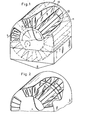
- a hollow cylinder 12 is rotatably mounted, on the outer circumference of which plates 8 are arranged so that they extend along the axis of the cylinder 12 and in the radial direction.
- the plates 8 are arranged at a small distance from one another in the circumferential direction and form reaction chambers 13 between them, the intermediate circumferential section of the cylinder 12 and the housing 11, which is barrel-shaped in the upper part and closely surrounds the free edge of the plates 8.
- the housing 11 contains a layer-forming network liquid in the lower part, the level of which is indicated at 7, the hollow cylinder 12 being partially immersed in the network liquid and being closed on the end faces to such an extent that no network liquid can penetrate into the hollow cylinder.
- the hollow cylinder 12 rotates in the direction of the arrow 4.
- an air inlet opening 5 is formed on the front side of the housing 11 and is associated with a corresponding air outlet opening (not shown) on the opposite end side of the housing 11.
- the air inlet opening 5 extends over the radial dimension of the reaction chambers 13 and is in the circumferential direction over about three reaction chambers.
- a gas inlet opening 6 is formed at a distance from the air inlet opening, which gas outlet opening 6 is also assigned on the opposite end face of the housing 11.
- the gas inlet and outlet openings likewise extend over the radial height of the reaction chambers 13, but over a larger peripheral section, as indicated by the sector 3 in FIG. 1.
- the gas is from the air inlet opening 5 which extends over the sector 1 inlet opening 6 arranged at a distance corresponding to the sector 2, which extends for example in the circumferential direction over two reaction chambers 13.
- the plates 8 and the outer circumference of the hollow cylinder 12 are moved by the wetting liquid due to the rotational movement in the direction of the arrow 4, these surfaces dripping when they emerge. They arrive in sector 1 in front of the air inlet opening 5, through which dry hot air is introduced, which exits on the opposite end face of the housing 11 and is dried and heated again in a closed circuit outside the housing 11 before it is introduced again through the air inlet opening 5 .
- the layers located on the plates 8 and the corresponding circumferential sections of the hollow cylinder 12 are completely dried without coming into contact with the gases to be cleaned.
- the reaction chambers 13 enter sector 2, which separates the dry air stream introduced at 5 from the gas stream introduced at 6 and is designed as a sealing section between the two inlet openings 5 and 6.
- the gas flow entering at 6 in sector 3 flows through a plurality of reaction chambers 13 and occurs after reaction with the dry layer on the movable inner surfaces of the reaction chambers 13 by a geometrically g eartete opening on the opposite end of the housing purified from.
- the inner surfaces of the reaction chambers 13 provided with dry layers are then immersed in the wetting liquid again, these solid layers automatically detaching with the reaction products.
- the reaction products can partly go into solution in the wetting liquid or also partly undissolved, for example as salt, on the funnel-shaped bottom 9 of the Ge house 11 sink.
- a corresponding discharge device which is not shown, can be provided for discharging such undissolved substances.
- a flow can also be provided in the lower part of the housing 11 for the continuous or intermittent renewal of the network liquid.
- Such a flow of the wetting liquid preferably in the longitudinal direction of the reaction chambers 13 or the hollow cylinder 12, can promote the detachment of the solid layers, the wetting liquid being able to be cleaned in a closed circuit outside the housing.
- the layer-forming wetting liquid is constructed in such a way that the impurities and pollutants contained in the gases are bound to the solid surface layer formed on the movable inner surfaces of the reaction chambers 13 on contact with the latter, the surface layer being converted as a result of the reaction with the particles contained in the gas and exhausted.
- the exhausted layer is usually slightly dissolved in the wetting liquid.
- reagents are added to the wetting liquid which cause a change in the surface tension of the reacted layer when it is immersed again in the wetting liquid, thereby ensuring that even layers which normally do not easily detach in the untreated wetting liquid are detached automatically.
- the movable inner surfaces of the reaction chambers 13 are then wetted with fresh wetting liquid, whereupon the resulting liquid film is dried by the hot air stream to form a new solid surface layer.
- Water-soluble compounds which contain those contained in the gases are selected to form the surface layer Bind substances to the solid surface layer formed on the plates as a result of wetting.
- heating of the hollow cylinder 12 can be provided, which supports the drying. But it is also possible to use the hollow cylinder 12 for cooling. This allows the procedure for. be carried out in each case the most favorable temperature for the cleaning process, without having to take into account the special features of the layer drying.
- the temperature range of the gases to be cleaned is given an unprecedented range. It is advantageous for the implementation of the method if all substances which form a gel with a pore-rich structure or a framework structure when evaporating are dispensed with in the wetting liquid, since the highest reaction speeds are achieved on extremely smooth layers.
- baffle plates such as the baffle plates 10 which extend transversely to the reaction chambers 13 in FIG. 2, are provided, which result in a swirling of the gas flow and are fastened to the plates 8.
- the gas flow is introduced on the entry side in sector 3 via approximately half of the entry opening 6 and, in a corresponding manner, is returned on the exit side on the opposite end face through the remaining section of the entry opening 6.
- a reaction product is formed which reacts with another contaminant component in a subsequent reaction chamber in such a way that also it is separated from the gas.
- the described method and the reproduced device in particular allow industrial exhaust gases to be cleaned, the cleaning being able to be carried out without interruption by continuous regeneration of the solid layer.
- a gas such as nitrogen, can also be used to dry the reaction chamber which is immersed in the network liquid.
- drying gas it is also not necessary to run the drying gas in a closed circuit. It is also possible to provide the housing 11 with openings in the radial direction in the drying area, so that an inflow of drying gas is also possible in the radial direction.
Landscapes
- Chemical & Material Sciences (AREA)
- Chemical Kinetics & Catalysis (AREA)
- Engineering & Computer Science (AREA)
- Analytical Chemistry (AREA)
- Biomedical Technology (AREA)
- Environmental & Geological Engineering (AREA)
- Health & Medical Sciences (AREA)
- General Chemical & Material Sciences (AREA)
- Oil, Petroleum & Natural Gas (AREA)
- Gas Separation By Absorption (AREA)
- Treating Waste Gases (AREA)
- Separation Of Particles Using Liquids (AREA)
- Drying Of Solid Materials (AREA)
- Physical Or Chemical Processes And Apparatus (AREA)
Applications Claiming Priority (2)
| Application Number | Priority Date | Filing Date | Title |
|---|---|---|---|
| DE3344875 | 1983-12-12 | ||
| DE3344875A DE3344875C1 (de) | 1983-12-12 | 1983-12-12 | Verfahren und Vorrichtung zum Reinigen von Gasen |
Publications (3)
| Publication Number | Publication Date |
|---|---|
| EP0146885A2 true EP0146885A2 (fr) | 1985-07-03 |
| EP0146885A3 EP0146885A3 (en) | 1986-12-17 |
| EP0146885B1 EP0146885B1 (fr) | 1988-04-20 |
Family
ID=6216707
Family Applications (1)
| Application Number | Title | Priority Date | Filing Date |
|---|---|---|---|
| EP84115298A Expired EP0146885B1 (fr) | 1983-12-12 | 1984-12-12 | Procédé et dispositif d'épuration de gaz |
Country Status (5)
| Country | Link |
|---|---|
| US (1) | US4774060A (fr) |
| EP (1) | EP0146885B1 (fr) |
| JP (1) | JPS60147218A (fr) |
| BR (1) | BR8406272A (fr) |
| DE (2) | DE3344875C1 (fr) |
Cited By (1)
| Publication number | Priority date | Publication date | Assignee | Title |
|---|---|---|---|---|
| EP0381002A1 (fr) * | 1989-02-02 | 1990-08-08 | Besitzgesellschaft Möller mbH | Procédé de désorption d'adsorbants |
Families Citing this family (9)
| Publication number | Priority date | Publication date | Assignee | Title |
|---|---|---|---|---|
| DE3528122A1 (de) * | 1985-08-06 | 1987-02-12 | Richard Scheuchl | Anlage zur rueckgewinnung von loesungsmitteln aus einem prozessgasstrom |
| DE3618511A1 (de) * | 1986-06-02 | 1987-12-23 | Stubinen Utvecklings Ab | Verfahren und vorrichtung zur reinigung von schadstoffhaltigen gasen |
| US5364606A (en) * | 1993-03-01 | 1994-11-15 | General Electric Company | NOx reduction through the use of methane |
| DE4430231A1 (de) * | 1994-08-25 | 1996-02-29 | Ultralight Ag | Verfahren und Vorrichtung zur Reinigung von Gasen und Flüssigkeiten |
| DE19528722C2 (de) * | 1995-08-04 | 2000-03-23 | Schmidt Ag Geb | Vorrichtung und Verfahren zur Reinigung von Abgasen mittels Naßadsorption |
| DE60203670T2 (de) * | 2001-09-01 | 2005-09-08 | Haldor Topsoe A/S | Verfahren zur Verteilung von Gas, Gasverteilungsvorrichtung und Schalldämpferkatalysatorsystem |
| DE10154533A1 (de) * | 2001-11-07 | 2003-05-28 | Arancibia Eduardo Enrique Romo | Filter zur Neutralisierung schädlicher Gase und zur Verminderung von Partikeln |
| AU2002347645A1 (en) * | 2002-09-20 | 2004-04-08 | Ruben Ramos De La Fuente | System and device for mass transfer and elimination of contaminants |
| CN111991961A (zh) * | 2020-09-07 | 2020-11-27 | 郝柯柯 | 一种纺织生产用纺织车间的空气净化系统 |
Family Cites Families (7)
| Publication number | Priority date | Publication date | Assignee | Title |
|---|---|---|---|---|
| US2832666A (en) * | 1954-12-23 | 1958-04-29 | Cornell Aeronautical Labor Inc | Method and apparatus for continuously carrying out gas reactions which require a high temperature to promote the reaction and papid cooling to preserve the reaction product |
| US3211148A (en) * | 1962-05-25 | 1965-10-12 | Jr John E Galajda | Rotary disk oxygenator and heater |
| FR1459673A (fr) * | 1968-12-19 | 1966-11-18 | Combustion Eng | Procédé et appareil pour la mise en contact d'un liquide et d'un gaz |
| DE2712216C2 (de) * | 1977-03-19 | 1984-01-05 | Kernforschungsanlage Jülich GmbH, 5170 Jülich | Verfahren und Vorrichtung zum Reinigen von heißen Gasen |
| SU643764A1 (ru) * | 1977-09-13 | 1979-01-25 | Всесоюзный Научно-Исследовательский Институт Охраны Труда Вцспс | Индикатор давлени |
| JPS6039062Y2 (ja) * | 1980-03-14 | 1985-11-22 | 株式会社西部技研 | ガス吸収装置 |
| JPS6039063Y2 (ja) * | 1980-05-30 | 1985-11-22 | 東洋紡績株式会社 | 有害ガス除去装置 |
-
1983
- 1983-12-12 DE DE3344875A patent/DE3344875C1/de not_active Expired
-
1984
- 1984-12-07 BR BR8406272A patent/BR8406272A/pt not_active IP Right Cessation
- 1984-12-12 EP EP84115298A patent/EP0146885B1/fr not_active Expired
- 1984-12-12 JP JP59262668A patent/JPS60147218A/ja active Granted
- 1984-12-12 DE DE8484115298T patent/DE3470462D1/de not_active Expired
-
1986
- 1986-09-19 US US06/910,345 patent/US4774060A/en not_active Expired - Fee Related
Cited By (1)
| Publication number | Priority date | Publication date | Assignee | Title |
|---|---|---|---|---|
| EP0381002A1 (fr) * | 1989-02-02 | 1990-08-08 | Besitzgesellschaft Möller mbH | Procédé de désorption d'adsorbants |
Also Published As
| Publication number | Publication date |
|---|---|
| DE3344875C1 (de) | 1985-07-11 |
| US4774060A (en) | 1988-09-27 |
| DE3470462D1 (en) | 1988-05-26 |
| BR8406272A (pt) | 1985-08-27 |
| JPS60147218A (ja) | 1985-08-03 |
| JPH0475048B2 (fr) | 1992-11-27 |
| EP0146885B1 (fr) | 1988-04-20 |
| EP0146885A3 (en) | 1986-12-17 |
Similar Documents
| Publication | Publication Date | Title |
|---|---|---|
| DE19629500C1 (de) | Multiwäscher und Verfahren zur Totalreinigung von Gasen | |
| DE69706306T2 (de) | Kontinuierliches system zum einfangen und entfernen von gasmolekülen | |
| DE2621953C3 (de) | Vorrichtung zum Kontaktieren von fließfähigen Stoffen mit Feststoffen | |
| DE2626939A1 (de) | Verfahren und vorrichtung zum abtrennen von unerwuenschten gasfoermigen bestandteilen aus einem abgas | |
| DE2156455A1 (de) | Verfahren und Vorrichtung zur Gasabsorption | |
| EP0146885B1 (fr) | Procédé et dispositif d'épuration de gaz | |
| DE1444479B2 (de) | Vorrichtung zur Abscheidung von Nebeln und Stäuben durch Anwendung eines Drucksprunges im Gasstrom | |
| DE2712216C2 (de) | Verfahren und Vorrichtung zum Reinigen von heißen Gasen | |
| EP0376356A1 (fr) | Méthode et procédé pour séparer des composants indésirables d'un gaz d'échappement | |
| DE1619838A1 (de) | Gasabscheider | |
| CH643149A5 (de) | Verfahren und vorrichtung zum kontinuierlichen thermischen behandeln von pumpfaehigen stoffen in duenner schicht. | |
| DE2440848A1 (de) | Verfahren zum fortlaufenden trennen der komponenten eines stoffes und vorrichtung zum durchfuehren des verfahrens | |
| DD241370A5 (de) | Einrichtung zur nassgasreinigung | |
| EP0206019A1 (fr) | Procédé d'épuration des gaz d'échappement chauds | |
| DE3313943A1 (de) | Verfahren und vorrichtung zum kontinuierlichen austausch von in einem chemischen und/oder physikalischen vorgang, wie z. b. einem filter-, einem adsorptions- oder trockenvorgang, verbrauchten regenerierbaren kontaktmitteln, wie filtermaterialien, trockenmitteln, adsorbermaterialien oder katalysatoren | |
| DE2919463C2 (de) | Vorrichtung für den Stoff- und/oder direkten Wärmeaustausch und zur Mischung von gasförmigen und/oder flüssigen bzw. festen Stoffen | |
| DE2843880A1 (de) | Vorrichtung zum entfernen mindestens eines bestandteils aus einem aerosolstrom | |
| DE1419251B2 (de) | Adsorptionsapparat | |
| DE2029994A1 (de) | Vorrichtung zur Umsetzung von Gasen oder Dämpfen mit Flüssigkeiten oder in Flüssigkeiten fein verteilten Stoffen | |
| DE2234275C3 (de) | Vorrichtung zum Entschwefeln von Rauchgas | |
| DE102010017614A1 (de) | Reinigung von Abluft | |
| DE745223C (de) | Vorrichtung zum Adsorbieren von Gasen und Daempfen mit selbsttaetiger Wiederbrauchbarmachung der adsorbierenden Stoffe | |
| DE1050316B (de) | Verfahren und Einrichtung zum Inberuehrungbringen einer Fluessigkeit mit einem Gas oder Dampf | |
| DE102004049931B4 (de) | Vorrichtung und Verfahren zum Abscheiden von Flüssigkeits- und/oder Festkörperteilchen aus einem Gasstrom | |
| DE3426015A1 (de) | Spruehwaescher und verfahren zur gasreinigung |
Legal Events
| Date | Code | Title | Description |
|---|---|---|---|
| PUAI | Public reference made under article 153(3) epc to a published international application that has entered the european phase |
Free format text: ORIGINAL CODE: 0009012 |
|
| AK | Designated contracting states |
Designated state(s): CH DE FR GB IT LI NL SE |
|
| RTI1 | Title (correction) | ||
| PUAL | Search report despatched |
Free format text: ORIGINAL CODE: 0009013 |
|
| AK | Designated contracting states |
Kind code of ref document: A3 Designated state(s): CH DE FR GB IT LI NL SE |
|
| 17P | Request for examination filed |
Effective date: 19870122 |
|
| 17Q | First examination report despatched |
Effective date: 19870706 |
|
| GRAA | (expected) grant |
Free format text: ORIGINAL CODE: 0009210 |
|
| AK | Designated contracting states |
Kind code of ref document: B1 Designated state(s): CH DE FR GB IT LI NL SE |
|
| GBT | Gb: translation of ep patent filed (gb section 77(6)(a)/1977) | ||
| REF | Corresponds to: |
Ref document number: 3470462 Country of ref document: DE Date of ref document: 19880526 |
|
| ITF | It: translation for a ep patent filed | ||
| ET | Fr: translation filed | ||
| PLBE | No opposition filed within time limit |
Free format text: ORIGINAL CODE: 0009261 |
|
| STAA | Information on the status of an ep patent application or granted ep patent |
Free format text: STATUS: NO OPPOSITION FILED WITHIN TIME LIMIT |
|
| 26N | No opposition filed | ||
| ITTA | It: last paid annual fee | ||
| EAL | Se: european patent in force in sweden |
Ref document number: 84115298.6 |
|
| PGFP | Annual fee paid to national office [announced via postgrant information from national office to epo] |
Ref country code: DE Payment date: 19950222 Year of fee payment: 11 |
|
| PGFP | Annual fee paid to national office [announced via postgrant information from national office to epo] |
Ref country code: SE Payment date: 19951130 Year of fee payment: 12 |
|
| PGFP | Annual fee paid to national office [announced via postgrant information from national office to epo] |
Ref country code: GB Payment date: 19951204 Year of fee payment: 12 |
|
| PGFP | Annual fee paid to national office [announced via postgrant information from national office to epo] |
Ref country code: FR Payment date: 19951219 Year of fee payment: 12 |
|
| PGFP | Annual fee paid to national office [announced via postgrant information from national office to epo] |
Ref country code: CH Payment date: 19951222 Year of fee payment: 12 |
|
| PGFP | Annual fee paid to national office [announced via postgrant information from national office to epo] |
Ref country code: NL Payment date: 19951230 Year of fee payment: 12 |
|
| PG25 | Lapsed in a contracting state [announced via postgrant information from national office to epo] |
Ref country code: DE Effective date: 19960903 |
|
| PG25 | Lapsed in a contracting state [announced via postgrant information from national office to epo] |
Ref country code: GB Effective date: 19961212 |
|
| PG25 | Lapsed in a contracting state [announced via postgrant information from national office to epo] |
Ref country code: SE Effective date: 19961213 |
|
| PG25 | Lapsed in a contracting state [announced via postgrant information from national office to epo] |
Ref country code: LI Effective date: 19961231 Ref country code: CH Effective date: 19961231 |
|
| PG25 | Lapsed in a contracting state [announced via postgrant information from national office to epo] |
Ref country code: NL Effective date: 19970701 |
|
| GBPC | Gb: european patent ceased through non-payment of renewal fee |
Effective date: 19961212 |
|
| REG | Reference to a national code |
Ref country code: CH Ref legal event code: PL |
|
| PG25 | Lapsed in a contracting state [announced via postgrant information from national office to epo] |
Ref country code: FR Effective date: 19970829 |
|
| NLV4 | Nl: lapsed or anulled due to non-payment of the annual fee |
Effective date: 19970701 |
|
| EUG | Se: european patent has lapsed |
Ref document number: 84115298.6 |
|
| REG | Reference to a national code |
Ref country code: FR Ref legal event code: ST |