EP0146949A2 - Procédé pour la production de nitrate d'ammonium - Google Patents
Procédé pour la production de nitrate d'ammonium Download PDFInfo
- Publication number
- EP0146949A2 EP0146949A2 EP84116069A EP84116069A EP0146949A2 EP 0146949 A2 EP0146949 A2 EP 0146949A2 EP 84116069 A EP84116069 A EP 84116069A EP 84116069 A EP84116069 A EP 84116069A EP 0146949 A2 EP0146949 A2 EP 0146949A2
- Authority
- EP
- European Patent Office
- Prior art keywords
- ammonium nitrate
- vapor
- stage
- pressure
- neutralization
- Prior art date
- Legal status (The legal status is an assumption and is not a legal conclusion. Google has not performed a legal analysis and makes no representation as to the accuracy of the status listed.)
- Granted
Links
- PAWQVTBBRAZDMG-UHFFFAOYSA-N 2-(3-bromo-2-fluorophenyl)acetic acid Chemical compound OC(=O)CC1=CC=CC(Br)=C1F PAWQVTBBRAZDMG-UHFFFAOYSA-N 0.000 title claims abstract description 65
- 238000000034 method Methods 0.000 title claims abstract description 34
- 238000004519 manufacturing process Methods 0.000 title abstract description 11
- XLYOFNOQVPJJNP-UHFFFAOYSA-N water Chemical compound O XLYOFNOQVPJJNP-UHFFFAOYSA-N 0.000 claims abstract description 50
- QGZKDVFQNNGYKY-UHFFFAOYSA-N Ammonia Chemical compound N QGZKDVFQNNGYKY-UHFFFAOYSA-N 0.000 claims abstract description 45
- 238000006386 neutralization reaction Methods 0.000 claims abstract description 31
- GRYLNZFGIOXLOG-UHFFFAOYSA-N Nitric acid Chemical compound O[N+]([O-])=O GRYLNZFGIOXLOG-UHFFFAOYSA-N 0.000 claims abstract description 26
- 229910017604 nitric acid Inorganic materials 0.000 claims abstract description 23
- 229910021529 ammonia Inorganic materials 0.000 claims abstract description 19
- 238000006243 chemical reaction Methods 0.000 claims description 27
- 239000012141 concentrate Substances 0.000 claims description 7
- 238000001704 evaporation Methods 0.000 claims description 4
- 230000008020 evaporation Effects 0.000 claims description 4
- 239000007858 starting material Substances 0.000 claims description 3
- 238000009833 condensation Methods 0.000 claims 1
- 230000005494 condensation Effects 0.000 claims 1
- 238000002360 preparation method Methods 0.000 claims 1
- 238000011084 recovery Methods 0.000 claims 1
- 239000000243 solution Substances 0.000 description 40
- 239000011541 reaction mixture Substances 0.000 description 13
- 238000000354 decomposition reaction Methods 0.000 description 11
- 239000011552 falling film Substances 0.000 description 10
- GQPLMRYTRLFLPF-UHFFFAOYSA-N Nitrous Oxide Chemical compound [O-][N+]#N GQPLMRYTRLFLPF-UHFFFAOYSA-N 0.000 description 8
- 239000007789 gas Substances 0.000 description 7
- 230000007423 decrease Effects 0.000 description 5
- 239000007788 liquid Substances 0.000 description 5
- 238000000605 extraction Methods 0.000 description 4
- 238000005259 measurement Methods 0.000 description 4
- 229960001730 nitrous oxide Drugs 0.000 description 4
- 230000015572 biosynthetic process Effects 0.000 description 3
- 239000000470 constituent Substances 0.000 description 3
- 239000000463 material Substances 0.000 description 3
- 239000001272 nitrous oxide Substances 0.000 description 3
- 238000000926 separation method Methods 0.000 description 3
- 230000001174 ascending effect Effects 0.000 description 2
- 238000007599 discharging Methods 0.000 description 2
- 238000010438 heat treatment Methods 0.000 description 2
- 238000002156 mixing Methods 0.000 description 2
- 239000000203 mixture Substances 0.000 description 2
- 230000007935 neutral effect Effects 0.000 description 2
- 239000012071 phase Substances 0.000 description 2
- 239000000376 reactant Substances 0.000 description 2
- 230000008719 thickening Effects 0.000 description 2
- 206010016352 Feeling of relaxation Diseases 0.000 description 1
- JGFZNNIVVJXRND-UHFFFAOYSA-N N,N-Diisopropylethylamine (DIPEA) Chemical compound CCN(C(C)C)C(C)C JGFZNNIVVJXRND-UHFFFAOYSA-N 0.000 description 1
- 238000010521 absorption reaction Methods 0.000 description 1
- 230000002378 acidificating effect Effects 0.000 description 1
- 239000008346 aqueous phase Substances 0.000 description 1
- 238000009835 boiling Methods 0.000 description 1
- 238000001311 chemical methods and process Methods 0.000 description 1
- 238000001514 detection method Methods 0.000 description 1
- 238000010586 diagram Methods 0.000 description 1
- 238000010790 dilution Methods 0.000 description 1
- 239000012895 dilution Substances 0.000 description 1
- 238000001035 drying Methods 0.000 description 1
- 230000007613 environmental effect Effects 0.000 description 1
- 239000002360 explosive Substances 0.000 description 1
- 239000013505 freshwater Substances 0.000 description 1
- 238000005469 granulation Methods 0.000 description 1
- 230000003179 granulation Effects 0.000 description 1
- 230000017525 heat dissipation Effects 0.000 description 1
- 238000012423 maintenance Methods 0.000 description 1
- 235000013842 nitrous oxide Nutrition 0.000 description 1
- 230000002040 relaxant effect Effects 0.000 description 1
- 230000000630 rising effect Effects 0.000 description 1
- 238000012619 stoichiometric conversion Methods 0.000 description 1
- 239000002351 wastewater Substances 0.000 description 1
Images
Classifications
-
- C—CHEMISTRY; METALLURGY
- C01—INORGANIC CHEMISTRY
- C01C—AMMONIA; CYANOGEN; COMPOUNDS THEREOF
- C01C1/00—Ammonia; Compounds thereof
- C01C1/18—Nitrates of ammonium
- C01C1/185—Preparation
Definitions
- the present invention relates to a process for the production of ammonium nitrate, the heat of neutralization released from the reaction of nitric acid and ammonia being used both for the production of pure water vapor and for further concentration of the ammonium nitrate solutions formed.
- the ammonium nitrate solution emerging from the reactor reaches a concentration of about 90%.
- the vapors formed in the reactor are used to warm up the reactants before they enter the reactor or to concentrate nitric acid before they enter the reactor.
- the second group of processes works at higher pressures than the first group, ie above 3 bar, and the temperatures are then above 160 ° C.
- An ammonium nitrate solution which is only one, is formed in the reactor Concentration of 70 to about 80 wt .-% reached.
- the vapor discharged from the reactor as explained above, has a higher pressure and thus higher temperatures. It can therefore be used to further concentrate the ammonium nitrate solution.
- the ammonium nitrate solution originating from the reactor is then concentrated in a zone or in a container by relaxing and heating by means of the vapor discharged from the reactor.
- the aqueous ammonium nitrate solution relaxes, forming vapors at the expense of the sensible Warmth of solution.
- This thickening process is supported by the fact that the pure water vapor of approximately 3 kg / cm 2 (2.943 bar) obtained by means of the heat exchanger arranged in the reactor sprinkles a heat exchanger which is attached in the evaporator.
- FR-A 15 74 094 relates to a two-stage process for the production of ammonium nitrate.
- first stage 95 to 99.75% of the nitric acid is neutralized, part of the reaction mixture is passed into a second neutralization stage and continuously drawn off there.
- Both neutralization stages always work under the same pressure, for which a range from 1 to 10 bar is specified.
- the nitric acid used can have concentrations of 40 to 70% by weight. In the first stage, it is neutralized to 95 to 99.75%.
- the heat of reaction released brings the reaction mixture to a boil, thus contributing to the circulation of the solution and concentrating it.
- the vapor formed is drawn off at the top of the reactor.
- Dispensing with concentrating the ammonium nitrate solution by means of the pure water vapor leads to an increase in the amount of pure water vapor which occurs regardless of the part of the heat of reaction which is required, for example, as vapors for the production of the ammonium nitrate solution not sure that the extraction of pure water vapor is always optimal.
- reaction conditions cannot be kept completely constant in the long run, but deviations result from external influences, such as fluctuations in the concentration and temperature of the starting materials (aqueous nitric acid, ammonia gas), there will always be a corresponding ratio of the amount of heat , which would be theoretically usable as pure water vapor and the proportion of the heat of reaction which is required in the form of vapors for the execution of the process (concentration of the ammonium nitrate solution).
- the object was therefore to provide a process for the production of ammonium nitrate which avoids the disadvantages mentioned above and in a simple manner enables optimum use of the heat of reaction, regardless of the respective fluctuations in the operating conditions.
- the object is achieved by a process for the production of ammonium nitrate by reacting / nitric acid with ammonia in two stages at elevated temperature, evaporation of the ammonium nitrate melt formed and extraction of pure water vapor, thereby characterized is characterized in that the neutralization in the first stage is carried out under a pressure of 3.4 to 4.8 bar and in the second stage without pressure, the heat of reaction released in the first stage is used to produce pure water vapor, the amount released of the generated pure water vapor and thus the reaction temperature of the first neutralization stage is controlled via the pressure of the vapors leaving the first neutralization stage and the vapors are under the same pressure as the first neutralization stage.
- the present invention relates to a two-stage process for the production of ammonium nitrate, with 95 to 99.8% by weight of the nitric acid used being neutralized with ammonia in the first stage.
- ammonia and nitric acid are intimately mixed with ammonium nitrate already formed at temperatures of 172 to 185 ° C. in a reactor which is part of a circulation system. This mixture flows through the reactor and gives off the heat of reaction released to a heat exchanger built into the reactor.
- the heat exchanger is operated with pure water and removes the heat of neutralization in the form of pure water vapor, which has a pressure of about 3 to 4 bar.
- the reactor is connected to a separator.
- the reaction mixture passes from the reactor to the separator, from which a part is removed for further processing.
- the remaining amount of the reaction mixture is fed to the reactor again and serves to take up the reactants nitric acid and ammonia.
- the vapor formed is discharged via the separator directly into a closed line system and always has the pressure of 3.4 to 4.8 bar prevailing in the separator and thus in the first neutralization stage.
- the reaction mixture which circulates in the circulation system is used to remove just that amount of heat which is required for carrying out the process.
- the part of the heat of reaction that is also available is obtained in the form of pure water vapor, taking into account the reaction conditions present in the circulation system.
- the preheated materials namely aqueous nitric acid and liquid or gaseous ammonia
- the reactor has a zone for mixing the feedstocks with ammonium nitrate solution already formed and a built-in heat exchanger that is operated with pure water.
- the reaction mixture heats up as a result of the heat of neutralization released, flows through the reactor from bottom to top and gives off part of the heat of reaction to the heat exchanger.
- the pure water in the heat exchanger evaporates and the steam formed is fed to a steam drum.
- the steam drum fulfills two tasks: on the one hand it feeds water into the heat exchanger and on the other hand it collects the water vapor formed and releases a quantity of it in accordance with the respective reaction conditions.
- the reaction mixture passes through a separator from the reactor. There the reaction mixture is separated into an aqueous phase containing ammonium nitrate and a water vapor (vapor) phase. Part of the aqueous ammonium nitrate phase returns to the zone of the reactor in which the feed products are mixed with the ammonium nitrate solution already formed. The remaining part of the ammonium nitrate solution is withdrawn from the separator and sent for further processing.
- a circulation system is thus formed from the reactor, the separator and the pipe sections connecting them to one another.
- the pressure of the vapor leaving the separator is measured.
- a pressure signal is generated which acts on a control unit.
- This control unit controls a control valve which is installed in the line leaving the steam drum and discharging water vapor.
- An increase in the vapor pressure means that more heat is dissipated than is required to carry out the process and consequently too little heat in the form of pure what steam is obtained.
- the increasing vapor pressure triggers a signal on the control unit via the transmitter, the opening of the control valve resulting in increased evaporation of water in the steam drum. This lowers the temperature in the steam drum and thus also the temperature in the heat exchanger connected to the steam drum, which is installed in the reactor vessel.
- the increase in the temperature gradient (aqueous ammonium nitrate solution flowing around the heat exchanger in the reactor / water in the heat exchanger) leads to an increased formation of water vapor in the heat exchanger and thus a corresponding decrease in the temperature in the ammonium nitrate solution.
- the concentration of the aqueous ammonium nitrate solution drops, ie more water remains in the ammonium nitrate solution than before.
- fewer vapors form than before and the pressure of the escaping vapors decreases.
- the control unit causes the control valve to dress in the water vapor discharge line. As a result, less heat in the form of water vapor is removed from the reaction mixture which flows around the heat exchanger, and the pressure and the temperature rise both in the steam drum and in the circulation system.
- the throttling of the control valve is maintained until the specified target value of the vapor pressure is reached.
- a decrease in the vapor pressure means that less heat is generated than is required to carry out the process and consequently too much heat in the form of pure water steam is obtained.
- the falling vapor pressure triggers a signal on the control unit, which triggers a throttling of the control valve.
- less water vapor is removed from the steam drum, ie pressure and temperature rise both in the steam drum and in the circulation system. Because more heat remains in the circulation system than before, it increases the amount of vapors and the pressure of the vapors increases.
- control unit causes the control valve in the line carrying water vapor to open.
- control valve in the line carrying water vapor As a result, more heat is dissipated than before in the form of water vapor, pressure and temperature drop both in the steam drum and in the circulation system. The increased water vapor absorption is maintained until the specified target value of the vapor pressure is reached.
- any vapors still present are separated off in this container and the reaction mixture, which has, for example, an ammonium nitrate concentration of 80% by weight, is fed to a falling film evaporator in which the required thickening to a final value of ⁇ 95% by weight ammonium nitrate takes place.
- the product leaving the falling film evaporator can be fed to further processing, such as drying, granulation or pelleting.
- the falling film evaporator is operated with negative pressure and heated with the vapors that come from the separator of the circulation system.
- the vapors condense here and the resulting condensate is drawn off from the lower part of the heat exchanger which is installed in the falling film evaporator and fed to a separator.
- the other part of the vapor from the first neutralization stage is used to heat up the feed materials.
- the non-condensable gases (mainly N 2 O) which are always present in small amounts in the vapor are separated from the vapor condensate in the separator and are measured after leaving the separator
- the non-condensable gases which mainly consist of N 2 0, are a decomposition product of ammonium nitrate
- ammonium nitrate is known to irreversibly break down into nitrous oxide and water. Due to the reaction conditions in the circulation system, the decomposition always takes place to a small extent and can also be tolerated.
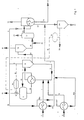
- the reaction mixture consisting of ammonium nitrate, water and residues of feedstocks which have not yet been completely converted, leaves the reactor 6 flowing through from bottom to top and passes through the pipe section 7 from the reactor 6 into the separator 8, where separation into liquid constituents and vapors takes place .
- the vapor is discharged via a line 8 and in each case has the pressure which corresponds to the reaction conditions prevailing in the circulation system.
- the concentration of the ammonium nitrate solution is important. If two diea sizes, such as pressure and temperature, are specified, the third size, in in this case the concentration of the solution, by itself.
- a decrease in the vapor pressure in line 9 throttles or closes the control valve 15. This removes a smaller proportion of the neutralization heat in the form of steam from the circulation system, the temperature in the circulation system begins to rise and, as more vapors are removed, also increases the concentration up to the desired value.
- an increase in the vapor pressure by opening the control valve 15 causes an increase in the water vapor output of the steam drum 11, i.e. A larger proportion of the neutral heat of the neutral is withdrawn from the circulation system in the form of water vapor, the temperature drops, at the same time less vapor is separated off and the concentration of the ammonium nitrate solution drops.
- the liquid constituents in the lower part of the separator 8 remain partly in the circulation system and flow from the separator 8 through the pipe section 5 to the reactor 6, where they are mixed with the feed products. Another part of the liquid constituents is fed from the separator 8 via a line 17 to a further separator 18, which operates under normal pressure. The vapors released in the process are discharged via a line 19 and serve to preheat the starting materials. For the sake of simplicity, the corresponding heat exchangers are not shown in the figure.
- the concentrated ammonium nitrate solution emerges from the bottom of the separator 18 into a line 20 and is removed from a line 21 with a residual amount of ammonia which opens into line 20, moves and arrives in a container 22. Vapors formed escape via line 23.
- the ammonium nitrate solution which is relatively concentrated, leaves the container 22 via the line 24 and enters a falling film evaporator 25, which contains a heat exchanger in the form of a tube bundle.
- the ammonium nitrate melt flows through the tubes of the tube bundle.
- the finished product leaves the falling film evaporator via a line 24 a and vapors formed are removed at a pressure of 0.4 bar via a line 26.
- the vapors of the separator 8 serve at the same time to heat the feed materials and to heat the falling film evaporator 25.
- the line 9, which leads the vapors out of the separator 8, is via a pulse line 16 to a control unit (pressure control) 14, which acts on the control valve 15 , connected.
- a line 10, which branches off from the line 9 behind the impulse line 16, supplies the heat exchanger 2 with vapors and a line 10 a, which is connected to line 10, feeds the heat exchanger 4 with vapors.
- Line 9 ends in the falling film evaporator 25 and sends vapors into the interstices of the tube bundle.
- the ammonium nitrate melt flows through the tubes of the tube bundle.
- the vapor from line 9 condenses and leaves the falling film evaporator via line 27.
- Condensate and non-condensable products coming from lines 10 and 10 a are fed to line 27 and, together with the mixture already present in this line 27, pass into a separator 28, in which a separation into condensable and non-condensable components he follows.
- the non-condensable components are mainly due to nitrous oxide, which always occurs in small quantities as a decomposition product of ammonium nitrate. Their quantity represents a measure of the degree of decomposition of ammonium nitrate. They leave the separator 28 via a line 29.
- a gas quantity measurement 30 is installed in line 29, which in turn is connected to the control valve 15 via a pulse line 31.
Landscapes
- Chemical & Material Sciences (AREA)
- Organic Chemistry (AREA)
- Inorganic Chemistry (AREA)
- Organic Low-Molecular-Weight Compounds And Preparation Thereof (AREA)
Applications Claiming Priority (2)
| Application Number | Priority Date | Filing Date | Title |
|---|---|---|---|
| DE3347404 | 1983-12-29 | ||
| DE3347404A DE3347404A1 (de) | 1983-12-29 | 1983-12-29 | Verfahren zur herstellung von ammonnitrat |
Publications (3)
| Publication Number | Publication Date |
|---|---|
| EP0146949A2 true EP0146949A2 (fr) | 1985-07-03 |
| EP0146949A3 EP0146949A3 (en) | 1988-01-07 |
| EP0146949B1 EP0146949B1 (fr) | 1989-05-17 |
Family
ID=6218348
Family Applications (1)
| Application Number | Title | Priority Date | Filing Date |
|---|---|---|---|
| EP84116069A Expired EP0146949B1 (fr) | 1983-12-29 | 1984-12-21 | Procédé pour la production de nitrate d'ammonium |
Country Status (6)
| Country | Link |
|---|---|
| US (1) | US4699773A (fr) |
| EP (1) | EP0146949B1 (fr) |
| DE (2) | DE3347404A1 (fr) |
| IN (1) | IN162644B (fr) |
| NO (1) | NO164231C (fr) |
| ZA (1) | ZA8410003B (fr) |
Cited By (1)
| Publication number | Priority date | Publication date | Assignee | Title |
|---|---|---|---|---|
| AU654632B1 (en) * | 1993-10-08 | 1994-11-10 | Uhde Gmbh | Reactor for the production of ammonium nitrate solution |
Families Citing this family (6)
| Publication number | Priority date | Publication date | Assignee | Title |
|---|---|---|---|---|
| FR2584386B1 (fr) * | 1985-07-04 | 1990-09-07 | Charbonnages Ste Chimique | Procede de fabrication de solutions concentrees de nitrate d'ammonium et installation pour la mise en oeuvre de ce procede |
| FR2755959B1 (fr) * | 1996-11-18 | 1998-12-24 | Kaltenbach Thuring Sa | Reacteur, procede et installation pour la fabrication de sels d'ammoniaque |
| ES2191538B1 (es) * | 2001-07-04 | 2005-02-16 | Incro, S.A. | Procedimiento e instalacion para la fabricacion de soluciones concentradas de nitrato amonico. |
| AR084075A1 (es) * | 2011-05-16 | 2013-04-17 | Orica Int Pte Ltd | Proceso integrado para producir nitrato de amonio |
| EP3263523A1 (fr) | 2016-06-27 | 2018-01-03 | YARA International ASA | Installation de production de nitrate d'ammonium et procédé de démarrage de celui-ci |
| JP7269761B2 (ja) * | 2019-03-15 | 2023-05-09 | 三菱重工業株式会社 | 原料流体の処理プラント、及び原料流体の処理方法 |
Family Cites Families (17)
| Publication number | Priority date | Publication date | Assignee | Title |
|---|---|---|---|---|
| CA532677A (fr) * | 1956-11-06 | A. Stengel Leonard | Procede pour la production de nitrate d'ammoniaque | |
| BE379205A (fr) * | 1930-06-02 | |||
| US2089957A (en) * | 1931-09-11 | 1937-08-17 | Du Pont | Manufacture of salts |
| US2551569A (en) * | 1947-05-24 | 1951-05-01 | Chemical Construction Corp | Manufacture of ammonium nitrate |
| US2974130A (en) * | 1954-11-22 | 1961-03-07 | Phillips Petroleum Co | Method of controlling pressure and liquid level in a vessel |
| US3174824A (en) * | 1956-10-01 | 1965-03-23 | Phillips Petroleum Co | Method of producing an aqueous solution of ammonium nitrate of predetermined concentration and apparatus therefor |
| US3085000A (en) * | 1958-12-23 | 1963-04-09 | Phillips Petroleum Co | Process control system |
| SU123150A1 (ru) * | 1959-01-02 | 1959-11-30 | Я.И. Кильман | Способ получени аммиачной селитры под давлением |
| US3451785A (en) * | 1961-07-06 | 1969-06-24 | Phillips Petroleum Co | Pressure relief system for pressure vessels |
| NL289830A (fr) * | 1962-03-08 | |||
| BE617291A (fr) * | 1962-05-04 | 1900-01-01 | ||
| FR1356054A (fr) * | 1962-05-04 | 1964-03-20 | Ucb Sa | Procédé de fabrication de nitrate d'ammonium |
| FR1439023A (fr) * | 1963-12-11 | 1966-05-20 | Exxon Research Engineering Co | Procédé et appareil pour conduire des réactions exothermiques d'oxyalkylation |
| GB1052469A (fr) * | 1963-12-13 | |||
| DE1288081B (de) * | 1965-05-07 | 1969-01-30 | Kaltenbach, Roger, Paris | Verfahren und Sättiger zur Herstellung von Ammoniumnitrat |
| SE322639B (fr) * | 1967-09-15 | 1970-04-13 | Fosfatbolaget Ab | |
| SU392947A1 (ru) * | 1971-07-29 | 1973-08-10 | Способ автоматического управления тепловым процессом |
-
1983
- 1983-12-29 DE DE3347404A patent/DE3347404A1/de not_active Withdrawn
-
1984
- 1984-12-12 IN IN935/DEL/84A patent/IN162644B/en unknown
- 1984-12-21 ZA ZA8410003A patent/ZA8410003B/xx unknown
- 1984-12-21 NO NO845174A patent/NO164231C/no unknown
- 1984-12-21 DE DE8484116069T patent/DE3478221D1/de not_active Expired
- 1984-12-21 EP EP84116069A patent/EP0146949B1/fr not_active Expired
- 1984-12-28 US US06/687,116 patent/US4699773A/en not_active Expired - Lifetime
Cited By (1)
| Publication number | Priority date | Publication date | Assignee | Title |
|---|---|---|---|---|
| AU654632B1 (en) * | 1993-10-08 | 1994-11-10 | Uhde Gmbh | Reactor for the production of ammonium nitrate solution |
Also Published As
| Publication number | Publication date |
|---|---|
| NO164231B (no) | 1990-06-05 |
| US4699773A (en) | 1987-10-13 |
| IN162644B (fr) | 1988-06-25 |
| ZA8410003B (en) | 1985-08-28 |
| EP0146949B1 (fr) | 1989-05-17 |
| DE3478221D1 (en) | 1989-06-22 |
| NO164231C (no) | 1990-09-12 |
| NO845174L (no) | 1985-07-01 |
| EP0146949A3 (en) | 1988-01-07 |
| DE3347404A1 (de) | 1985-07-11 |
Similar Documents
| Publication | Publication Date | Title |
|---|---|---|
| DE2617340A1 (de) | Nassoxydationsvorrichtung | |
| DE69708627T2 (de) | Verfahren zur kombinierten Erzeugung von Ammoniak und Harnstoff | |
| DE2726491A1 (de) | Verfahren zur kontinuierlichen herstellung von alkalialkoholaten | |
| EP0022181B1 (fr) | Procédé et installation pour la régénération d'acide sulfurique | |
| DE1467157C3 (de) | Verfahren zur Herstellung von Schwefelsäure | |
| EP1291339A2 (fr) | Procédé continu de préparation de monoéthanolamine, diéthanolamine et triéthanolamine | |
| DE102004012293A1 (de) | Verfahren und Anlage zur Herstellung von Schwefelsäure | |
| EP0146949B1 (fr) | Procédé pour la production de nitrate d'ammonium | |
| DE2809474C2 (fr) | ||
| DE3237653C2 (de) | Verfahren zur Herstellung von Harnstoff | |
| EP0021381B1 (fr) | Procédé pour la récupération de l'energie de pyrolyse dans la préparation de chlorure de vinyle par craquage thermique du dichloroéthane | |
| DE927744C (de) | Verfahren zur Gewinnung von Cyanwasserstoff | |
| EP0976704B1 (fr) | Procédé permettant une économie d' énergie dans l'oxychloruration d' éthylène | |
| DE2521507B2 (de) | Verfahren zur rueckgewinnung der harnstoff-, ammoniak- und kohlendioxidanteile aus dem beim einengen einer harnstoffloesung anfallenden dampfgemisch | |
| DE68906423T2 (de) | Verfahren zur konzentrierung der salpetersaeure. | |
| EP0124507B1 (fr) | Procédé pour l'obtention du furfural à partir des eaux résiduaires acides de la préparation de la cellulose et appareillage pour la mise en oeuvre de ce procédé | |
| DD202858A5 (de) | Verfahren und einrichtung zur erzeugung von ammonnitrat | |
| AT401048B (de) | Verfahren und vorrichtung zur entfernung von ammonium-verbindungen aus abwässern | |
| DE1197857B (de) | Verfahren zur Herstellung von Ammonnitrat | |
| DE2113428A1 (de) | Verfahren zur Umwandlung von Schwefeldioxyd in Schwefelsaeure | |
| DE1442971A1 (de) | Verfahren und Vorrichtung zum Konzentrieren und Reinigen von durch nassen Aufschlussgewonnener Phosphorsaeure | |
| DE102019105353B4 (de) | Verfahren zur Aufbereitung ammoniakhaltiger Flüssigkeiten und Anlage zur Durchführung des Verfahrens | |
| DE19920741B4 (de) | Verfahren zur Herstellung konzentrierter Salpetersäure | |
| DE3517531A1 (de) | Verfahren zur gewinnung von ammoniak aus schwefelwasserstoff- und/oder kohlendioxidhaltigem ammoniakwasser | |
| DE2617185B2 (de) | Verfahren zur kondensation von ammoniumcarbonat im rahmen der harnstoffsynthese |
Legal Events
| Date | Code | Title | Description |
|---|---|---|---|
| PUAI | Public reference made under article 153(3) epc to a published international application that has entered the european phase |
Free format text: ORIGINAL CODE: 0009012 |
|
| AK | Designated contracting states |
Designated state(s): BE DE FR GB IT NL |
|
| PUAL | Search report despatched |
Free format text: ORIGINAL CODE: 0009013 |
|
| AK | Designated contracting states |
Kind code of ref document: A3 Designated state(s): BE DE FR GB IT NL |
|
| 17P | Request for examination filed |
Effective date: 19880224 |
|
| RAP1 | Party data changed (applicant data changed or rights of an application transferred) |
Owner name: HOECHST AKTIENGESELLSCHAFT |
|
| 17Q | First examination report despatched |
Effective date: 19881019 |
|
| ITF | It: translation for a ep patent filed | ||
| GRAA | (expected) grant |
Free format text: ORIGINAL CODE: 0009210 |
|
| AK | Designated contracting states |
Kind code of ref document: B1 Designated state(s): BE DE FR GB IT NL |
|
| REF | Corresponds to: |
Ref document number: 3478221 Country of ref document: DE Date of ref document: 19890622 |
|
| ET | Fr: translation filed | ||
| GBT | Gb: translation of ep patent filed (gb section 77(6)(a)/1977) | ||
| PLBE | No opposition filed within time limit |
Free format text: ORIGINAL CODE: 0009261 |
|
| STAA | Information on the status of an ep patent application or granted ep patent |
Free format text: STATUS: NO OPPOSITION FILED WITHIN TIME LIMIT |
|
| 26N | No opposition filed | ||
| ITTA | It: last paid annual fee | ||
| PGFP | Annual fee paid to national office [announced via postgrant information from national office to epo] |
Ref country code: FR Payment date: 19941123 Year of fee payment: 11 |
|
| PGFP | Annual fee paid to national office [announced via postgrant information from national office to epo] |
Ref country code: GB Payment date: 19941213 Year of fee payment: 11 |
|
| PGFP | Annual fee paid to national office [announced via postgrant information from national office to epo] |
Ref country code: BE Payment date: 19941229 Year of fee payment: 11 |
|
| PGFP | Annual fee paid to national office [announced via postgrant information from national office to epo] |
Ref country code: NL Payment date: 19941231 Year of fee payment: 11 |
|
| PGFP | Annual fee paid to national office [announced via postgrant information from national office to epo] |
Ref country code: DE Payment date: 19950117 Year of fee payment: 11 |
|
| PG25 | Lapsed in a contracting state [announced via postgrant information from national office to epo] |
Ref country code: GB Effective date: 19951221 |
|
| PG25 | Lapsed in a contracting state [announced via postgrant information from national office to epo] |
Ref country code: BE Effective date: 19951231 |
|
| BERE | Be: lapsed |
Owner name: HOECHST A.G. Effective date: 19951231 |
|
| PG25 | Lapsed in a contracting state [announced via postgrant information from national office to epo] |
Ref country code: NL Effective date: 19960701 |
|
| GBPC | Gb: european patent ceased through non-payment of renewal fee |
Effective date: 19951221 |
|
| PG25 | Lapsed in a contracting state [announced via postgrant information from national office to epo] |
Ref country code: FR Effective date: 19960830 |
|
| NLV4 | Nl: lapsed or anulled due to non-payment of the annual fee |
Effective date: 19960701 |
|
| PG25 | Lapsed in a contracting state [announced via postgrant information from national office to epo] |
Ref country code: DE Effective date: 19960903 |
|
| REG | Reference to a national code |
Ref country code: FR Ref legal event code: ST |