EP0147013A2 - Tamis de perforation et méthode pour sa fabrication - Google Patents
Tamis de perforation et méthode pour sa fabrication Download PDFInfo
- Publication number
- EP0147013A2 EP0147013A2 EP84306398A EP84306398A EP0147013A2 EP 0147013 A2 EP0147013 A2 EP 0147013A2 EP 84306398 A EP84306398 A EP 84306398A EP 84306398 A EP84306398 A EP 84306398A EP 0147013 A2 EP0147013 A2 EP 0147013A2
- Authority
- EP
- European Patent Office
- Prior art keywords
- screen
- screens
- matched
- relatively thin
- cylindrical metal
- Prior art date
- Legal status (The legal status is an assumption and is not a legal conclusion. Google has not performed a legal analysis and makes no representation as to the accuracy of the status listed.)
- Granted
Links
Images

Classifications
-
- B—PERFORMING OPERATIONS; TRANSPORTING
- B23—MACHINE TOOLS; METAL-WORKING NOT OTHERWISE PROVIDED FOR
- B23P—METAL-WORKING NOT OTHERWISE PROVIDED FOR; COMBINED OPERATIONS; UNIVERSAL MACHINE TOOLS
- B23P15/00—Making specific metal objects by operations not covered by a single other subclass or a group in this subclass
- B23P15/26—Making specific metal objects by operations not covered by a single other subclass or a group in this subclass heat exchangers or the like
-
- B—PERFORMING OPERATIONS; TRANSPORTING
- B23—MACHINE TOOLS; METAL-WORKING NOT OTHERWISE PROVIDED FOR
- B23P—METAL-WORKING NOT OTHERWISE PROVIDED FOR; COMBINED OPERATIONS; UNIVERSAL MACHINE TOOLS
- B23P15/00—Making specific metal objects by operations not covered by a single other subclass or a group in this subclass
- B23P15/16—Making specific metal objects by operations not covered by a single other subclass or a group in this subclass plates with holes of very small diameter, e.g. for spinning or burner nozzles
-
- B—PERFORMING OPERATIONS; TRANSPORTING
- B26—HAND CUTTING TOOLS; CUTTING; SEVERING
- B26F—PERFORATING; PUNCHING; CUTTING-OUT; STAMPING-OUT; SEVERING BY MEANS OTHER THAN CUTTING
- B26F1/00—Perforating; Punching; Cutting-out; Stamping-out; Apparatus therefor
- B26F1/26—Perforating by non-mechanical means, e.g. by fluid jet
-
- Y—GENERAL TAGGING OF NEW TECHNOLOGICAL DEVELOPMENTS; GENERAL TAGGING OF CROSS-SECTIONAL TECHNOLOGIES SPANNING OVER SEVERAL SECTIONS OF THE IPC; TECHNICAL SUBJECTS COVERED BY FORMER USPC CROSS-REFERENCE ART COLLECTIONS [XRACs] AND DIGESTS
- Y10—TECHNICAL SUBJECTS COVERED BY FORMER USPC
- Y10T—TECHNICAL SUBJECTS COVERED BY FORMER US CLASSIFICATION
- Y10T29/00—Metal working
- Y10T29/49—Method of mechanical manufacture
- Y10T29/49826—Assembling or joining
- Y10T29/49908—Joining by deforming
- Y10T29/49938—Radially expanding part in cavity, aperture, or hollow body
- Y10T29/4994—Radially expanding internal tube
-
- Y—GENERAL TAGGING OF NEW TECHNOLOGICAL DEVELOPMENTS; GENERAL TAGGING OF CROSS-SECTIONAL TECHNOLOGIES SPANNING OVER SEVERAL SECTIONS OF THE IPC; TECHNICAL SUBJECTS COVERED BY FORMER USPC CROSS-REFERENCE ART COLLECTIONS [XRACs] AND DIGESTS
- Y10—TECHNICAL SUBJECTS COVERED BY FORMER USPC
- Y10T—TECHNICAL SUBJECTS COVERED BY FORMER US CLASSIFICATION
- Y10T428/00—Stock material or miscellaneous articles
- Y10T428/12—All metal or with adjacent metals
- Y10T428/12361—All metal or with adjacent metals having aperture or cut
-
- Y—GENERAL TAGGING OF NEW TECHNOLOGICAL DEVELOPMENTS; GENERAL TAGGING OF CROSS-SECTIONAL TECHNOLOGIES SPANNING OVER SEVERAL SECTIONS OF THE IPC; TECHNICAL SUBJECTS COVERED BY FORMER USPC CROSS-REFERENCE ART COLLECTIONS [XRACs] AND DIGESTS
- Y10—TECHNICAL SUBJECTS COVERED BY FORMER USPC
- Y10T—TECHNICAL SUBJECTS COVERED BY FORMER US CLASSIFICATION
- Y10T428/00—Stock material or miscellaneous articles
- Y10T428/12—All metal or with adjacent metals
- Y10T428/12479—Porous [e.g., foamed, spongy, cracked, etc.]
Definitions
- the present invention is in the general field of perforated plastic film and especially relates to vaccum perforating of plastic film.
- the invention particularly relates to metal screens or molding elements used in the vacuum perforation of plastic film and to a method of fabricating such screens.
- Perforated plastic film has many useful applications. It is used in gardening and farming to prevent the growth of grass and weeds while permitting moisture to be transmitted through the film to the soil beneath. Perforated film is also used for making disposable diapers, for example, see U.S. 3,814,101.
- U.S. 3,054,148 One of the earlier methods for vaccum perforation of plastic film is disclosed in U.S. 3,054,148.
- the patentee describes a stationary drum having a molding element or screen mounted around the outer surface of the drum and adapted to freely rotate thereon.
- a vacuum chamber is employed beneath the screen to create a pressure differential between the respective surfaces of the thermoplastic sheet to be perforated to cause the plasticized sheet to flow into openings provided in the screen and thereby cause a series of openings, holes or perforations to be formed in the plastic sheet or film.
- U.S. 4,151,240 provides a means for cooling the film after it has been perforated and debossed.
- U . S . 4,319,868 sets forth an apparatus for making a thermoplastic film having raised bosses with perforated tips. A particularly constructed embossing roll for effecting the desired film pattern is disclosed.
- U.S. 4,388,056 discloses an apparatus for continuously forming an air- laid fibrous web having oppositely phased, cylindrically undulating side edges and a predetermined basis weight distribution.
- An air-laying drum has a honeycomb type annular-shape frame including circumferentially extending ribs and transverse plates.
- a stationary adjustable air flow modulating means is disposed adjacent the radially inwardly disposed boundary of an arcuate portion of a circumferentially segmented annular-shape plenum, circumferentially spanning a plurality of plenum segments for adjusting a pressure drop across particular areas of the surface of the air-laying drum.
- Vacuum perforation of thin plastic films involves the extrusion of molten polymeric materials such as polyethylene and other plastic polymers though a slot die.
- the hot melt web of film or plastic sheet exiting the die impinges on a rotating cylindrical screen which is mounted on a stationary vacuum drum or roll.
- the vacuum roll has an axial slot and a set of seals extending longitudinally the length of its outside surface, beneath the area where the web of plastic impinges on the screen or molding element.
- a high vacuum from inside the screen is directed through the slot in the vacuum roll.
- the vacuum present within the slot forms or molds the plastic film or sheet to the screen and perforates it through the holes of the screen. At the same time, an airflow is produced which cools the film.
- the most important component of the vacuum processing equipment is the cylindrical screen.
- This molding element defines aesthetic and mechanical properties of the film as well as the geometric pattern of the perforated film.
- the desired screen pattern is nickel plated on a specially prepared cylindrical mandrel.
- a seamless cylindrical nickel screen of any predetermined or desired pattern can be produced.
- Other metals, such as copper may also be used.
- Some film products require the use of relatively thick screens, e.g. from 0.020 to 0.100 inches (0..0508-- 0.254 cm) thick, and also require that the walls of the patterned holes are straight and perpendicular to the screen surface.
- Present screen fabrication techniques as heretofore described are not capable of producing a screen meeting these requirements.
- the patterned holes on screens produced by nickel plating a prepared cylindrical mandrel, even with the application of specialized plating and post etching techniques, take the shape of inverted, truncated, concaved cones. The thicker the screen, the more exaggerated the effect becomes.
- a relatively thick, laminated, cylindrical metal screen or molding element for vacuum perforation of plastic film or sheets which comprises two or more relatively thin, cyclindrical metal screens, each of which has predetermined inside and outside diameters and a plurality of openings or holes therein of predetermined size and geometrical shape, which screens have been stacked and bonded together diametrically one inside the other, and having a desired thickness and a desired hole geometry wherein the holes have substantially straight walls which are perpendicular to the surface of the screen.
- a method for producing the screens comprising stacking and bonding together two or more matched relatively thin cylindrical metal screens diametrically one inside the other, each of said relatively thin metal screens having a plurality of holes therein which have substantially straight walls and which are perpendicular to the surface of their respective relatively thin cylindrical metal screen.
- matched sets of relatively thin, seamless, cylindrical metal screens are overplated with a thin layer of a bonding metal within specified tolerances wherein the inside diameter of the largest screen fits the outside diameter of the next largest screen.
- Each screen fits similarly inside the next largest screen and has a common reference mark on each end thereof for alignment.
- Two relatively thicker seamless metal sleeves of different diameters are prepared wherein the inside surface of the larger diameter sleeve is chrome plated and the outside surface of the smaller diameter sleeve is chrome plated.
- the inside diameter of the larger sleeve fits the outside diameter of the largest diameter matched screen within specified tolerances.
- the outside diameter of the smaller sleeve fits the inside diameter of the smallest diameter matched screen within specified tolerances.
- the entire inside surfaces and the matched screens are coated with an appropriate flux.
- the largest cyclindrical sleeve is cradled and clamped so as to retain its cylindrical shape.
- the largest diameter screen is malformed, slid inside the cradled sleeve and then reformed into its cylindrical shape.
- the next largest screen is then malformed and slid inside the reformed screen.
- the reference marks of the two screens are aligned and the screens are then pinned or otherwise fastened together.
- the smaller screen is then reformed into its cylindrical . shape.
- the remaining screens of the matched set are similarly assembled.
- the smaller diameter sleeve is installed similarly to the matched screens.
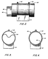
- FIG. 1 of the drawings vacuum process equipment and method for perforating plastic film or sheet therewith are schematically illustrated.
- a plastic polymer such as polyethylene is heated to a melt and extruded from an extruder E through a die D where a film web 10 is formed.
- the web 10 is directed onto a rotating cylindrical screen 11 having a desired pattern of holes which is turning clockwise as indicated by arrow A around a stationary vacuum roll or drum 12.
- a vacuum chamber 13 within the roll 12, longitudinal air slot 14 and seals.15 are employed to create a pressure differential between the respective surfaces of the thermoplastic sheet or web 10 to cause the plasticized sheet to flow into the holes in the screen in the direction indicated by the arrow B and therefore perforate the web 10.
- the perforated film web 10' travels onto a guide roll 16 and continues onto a wind-up roll 17. Additional guide rolls or tensioning rolls can be employed as desired as well as various film treating equipment.
- Seamless cylindrical nickel screens produced by plating are made by two principal methods.
- a mandrel is ground to a dimension corresponding to the desired dimension of the finished screen.
- the desired screen hole pattern is engraved on the mandrel either by spiral engraving or malett indexing techniques.
- a plating resist medium is applied to the surface of the mandrel, filling the pattern produced by the engraving.
- a finish grinding operation is employed to remove the plating resist medium from the land areas between the engraved pattern, so that only the land area will be subject to plating.
- Subsequent nickel plating of the mandrel forms the screen.
- the mandrel is cooled and the finished screen is removed therefrom.
- the other method of producing a seamless cylindrical nickel screen is similar to the foregoing method, except that instead of engraving the pattern on the mandrel, a special photographic negative of the pattern is created and wrapped around the mandrel. Exposing of the negative transfers the pattern to the mandrel in the form of a plating resist, leaving only the land areas of . the screen available for plating. The mandrel is then plated, forming the screen which is then removed from the mandrel to obtain the finished product.
- each successive screen of the set must fit diametrically inside the next larger diameter screen, with sufficient space allowed for the metal or tin-lead alloy plating of each screen.
- each screen of the set is typically geometrically identical. This means that each screen has the same number of holes, both axially and circumferentially, and that the radial centerlines of each hole of any one screen match identically the radial centerlines of the corresponding holes in all other screens in the set.
- the individual hole geometry of all the aligned holes in all the screens must generally be nearly identical.
- the inside diameter of each individual thin screen to be laminated may be calculated by the following. formula:
- the inside diameter of the outer solid metal sleeve may be calculated by the following formula:
- the inside diameter of the inner solid metal sleeve may be calculated by the following formula:
- matched sets of seamless, cylindrical metal (nickel) screens may be produced as follows:
- screens are generally prepared for particular film perforating operations, the use of the same mandrel is preferable. Should a number of laminated screens of the same pattern be produced, a number of mandrels may be used, as appropriate.
- a matched set of thin, seamless, cylindrical, nickel screens are prepared as set forth in detail hereinafter.
- the length and diameter of the screens is selected on the basis of the type of vacuum perforating equipment and the number of screens to be laminated.
- the thickness of each screen is determined on the basis of the type of hole wall shape desired.
- a screen thickness of approximately 0.005 inches (0.0127 cm) is preferred for providing hole walls that are substantially straight and perpendicular to the surface of the screen.
- Each screen of the matched set is overplated with a thin layer of a bonding material, preferably a tin-lead alloy.
- a bonding material preferably a tin-lead alloy.
- An alloy of ' 63 weight percent tin and 37 percent lead is especially preferred.
- An alloy layer of about 0.00025 inches (0.000635 centimeters) thick is most preferred.
- Each screen of the matched set is designed and produced so that after plating, the inside diameter of the largest screen fits, within a specified tolerance, the outside diameter of the next largest screen. In turn, each screen of the set fits similarly inside the next largest screen.
- Each screen of the set is designed and produced with a common reference or aligning mark at each end thereof. Alignment of the reference marks during assembly produces proper pattern hole alignment.
- Two seamless cylindrical nickel sleeves of different diameters are also required.
- the sleeves are about the same length of the thin screens.
- the thickness of the sleeves may be varied, but a thickness of approximately 0.010 inches (0.0254 centimeters) is especially preferred.
- the inside surface of the larger diameter sleeve, and the outside surface of the smaller diameter sleeve are chrome plated. A plating thickness of about 0.0005 inches (0.0127 centimeters) is most preferred.
- the sleeves are designed and produced so that after chrome plating, the inside diameter of the larger sleeve fits, within a specified tolerance, the outside diameter of the largest diameter thin screen, after the screen has been plated.
- the outside diameter of the smaller sleeve is designed and produced to fit the inside diameter of the smallest diameter thin screen of the matched set of screens, after the screen has been plated.
- the two sleeves are used as fixtures during the assembly and bonding operations as explained hereinafter.
- the tin-lead alloy plating applied to each screen provides the bonding medium for lamination.
- the chrome plating applied to the sleeves acts as a resist to prevent the tin screens being laminated from bonding to the sleeves.
- the larger cylindrical sleeve 20 is mounted in a cradle 21 and restrained therein so as to retain its cylindrical shape by two stiff outside diameter ring clamps 22 and 23. Any other suitable restraining or clamping means may be used.
- the largest diameter thin screen 30 of the matched set of screens is malformed or otherwise distorted and slid or positioned inside the larger diameter sleeve 20. The screen 30 is then reformed into its cylindrical shape.
- the next largest screen 31 is similarly malformed and slid inside the largest screen 30 of the assembly 40.
- Reference marks 32 on the ends of the two screens are aligned and the screens are pinned or otherwise fastened together.
- the remaining thin screens are similarly installed with the next largest thin screen being positioned inside the second thin screen 31 and so on, until each thin screen of the matched set of thin screens has been assembled.
- the smaller sleeve 24 is positioned within the smallest diameter thin screen in the same manner as the various thin screens were installed.
- an appropriate flux for example, a liquid solder flux having a pure resin base or a soldering paste containing zinc chloride, both manufactured by CG Electronics. Any other suitable flux may be used.
- the assembly 40 is transferred to an oven and uniformly heated to a temperature of about 400°F + 10°F (204.4°C + 5.56°C) or 390°F to 410°F (or 198.84°C to 209.96°C).
- the cylindrical nickel sleeves remain on the assembled screens.
- the sleeves act to uniformly restrain the screen laminates while permitting growth and shrinkage during heating and cooling cycles as they are preferably of the same material as the thin screens.
- the assembly is then allowed to cool in the oven to nearly room or ambient temperature. It is then removed from the oven for final operations.
- the outside sleeve is carefully axially cut and removed. Remaining flux residue is removed from the screen assembly with a suitable agent, for example, by washing with a degreasing liquid followed by a neutralizing wash of a 2 percent solution of muriatic acid. Any other suitable flux removing agent may be used.
- a suitable agent for example, by washing with a degreasing liquid followed by a neutralizing wash of a 2 percent solution of muriatic acid. Any other suitable flux removing agent may be used.
- the inside sleeve is then removed, leaving a finished laminated screen of a desired thickness.
- the , specific one of 63% tin-37% lead, plated to a thickness of 0.00025 inches (0.000635 centimeters) particularly meets the requirements of the fabricating system.
- Pure, plated nickel initiates embrittlement at approximately 425°F (218.3°C).
- Any bonding system selected must there- fore cure or flow at a temperature below the embrittle- ment temperature of the nickel plating.
- the tin-lead alloy preferred is the eutectic formulation of the two elements. The alloy melts and solidifies at 361°F (182.3°C).
- the instant bonding system is unique, in that, by plating each individual thin screen prior to assembly, difficult and messy applications of bonding mediums during assembly are avoided.
- the tin-lead alloy plating thickness of 0.00025 inches (0.000635 centimeters) is the optimum thickness to produce good bonding with minimum excess alloy.
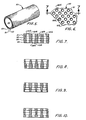
- a laminated screen 50 of the invention which comprises four thin screens 51, 52, 53 and 54 which have been stacked and bonded together in accordance with the foregoing procedure.
- the screen 50 has a pluarlity of openings or holes 50a therein.
- the holes 50a have walls 50b which are substantially straight as best seen in Fig. 7.
- the walls 50b are formed from the individual walls 51b, 52b, 53b and 54b of each of the tin screens 51, 52, 53 and 54, respectively.
- the truncated holes of the thin screens have been exaggerated.
- the effect of the multiscreen lamination provides hole walls which are substantially straight.
- the invention is particularly directed to a method of producing relatively thick seamless cylindrical metal screens, especially nickel screens, with holes or openings which are essentially straight and perpendicular to the screen surface
- the method can also be utilized to provide thick screens with an expanded variety of hole radial cross-sections. It is only essential that the basic hole radial centerlines of each screen laminate be the same.
- Figs. 8-10 illustrate some of the screen arrangements that can be achieved by using thin screens of different hole sizes. It can readily be appreciated that a wide variety of hole shapes and sizes can be obtained for providing a particular hole effect in a thermoplastic film or sheet. It is preferred for the holes to have a diameter of from about 0.015 to about 0.02 inches (0.0381 - 0.0508 cm). It is also preferred for there to about 100 to 20,000 holes per square inch (15.5 to 3100 holes/cm 2 ) of screen surface.
- thermoplastic sheets or film made from polyolefins especially polyethylene and polypropylene
- it can be used with other types of thermoplastic films as desired.
Landscapes
- Engineering & Computer Science (AREA)
- Mechanical Engineering (AREA)
- Life Sciences & Earth Sciences (AREA)
- Forests & Forestry (AREA)
- Laminated Bodies (AREA)
- Perforating, Stamping-Out Or Severing By Means Other Than Cutting (AREA)
- Blow-Moulding Or Thermoforming Of Plastics Or The Like (AREA)
- Extrusion Moulding Of Plastics Or The Like (AREA)
Applications Claiming Priority (2)
| Application Number | Priority Date | Filing Date | Title |
|---|---|---|---|
| US06/534,359 US4543299A (en) | 1983-09-21 | 1983-09-21 | Laminated, seamless, cylindrical metal screen for vacuum perforation of thermoplastic film |
| US534359 | 1983-09-21 |
Publications (3)
| Publication Number | Publication Date |
|---|---|
| EP0147013A2 true EP0147013A2 (fr) | 1985-07-03 |
| EP0147013A3 EP0147013A3 (en) | 1986-09-24 |
| EP0147013B1 EP0147013B1 (fr) | 1991-03-20 |
Family
ID=24129707
Family Applications (1)
| Application Number | Title | Priority Date | Filing Date |
|---|---|---|---|
| EP84306398A Expired - Lifetime EP0147013B1 (fr) | 1983-09-21 | 1984-09-19 | Tamis de perforation et méthode pour sa fabrication |
Country Status (7)
| Country | Link |
|---|---|
| US (1) | US4543299A (fr) |
| EP (1) | EP0147013B1 (fr) |
| JP (1) | JPS60155436A (fr) |
| BE (1) | BE905121Q (fr) |
| CA (1) | CA1243176A (fr) |
| DE (1) | DE3484298D1 (fr) |
| ES (1) | ES296810Y (fr) |
Cited By (2)
| Publication number | Priority date | Publication date | Assignee | Title |
|---|---|---|---|---|
| FR2763273A1 (fr) * | 1997-05-16 | 1998-11-20 | Guial | Grille avec ouvertures en forme d'ellipse pour le percement en continu d'un film thermoplastique, procede de fabrication et tambour rotatif mettant en oeuvre une telle grille |
| CN104972271A (zh) * | 2015-04-22 | 2015-10-14 | 天津大学 | 一种微结构阵列器件模芯制造方法 |
Families Citing this family (12)
| Publication number | Priority date | Publication date | Assignee | Title |
|---|---|---|---|---|
| US5327825A (en) * | 1993-05-12 | 1994-07-12 | Transfer Print Foils, Inc. | Seamless holographic transfer |
| US5562932A (en) * | 1994-06-14 | 1996-10-08 | Tredegar Industries, Inc. | Screen for producing a perforated film |
| US5718928A (en) * | 1994-06-14 | 1998-02-17 | Tredegar Industries, Inc. | Screen for producing a perforated film |
| US5591510A (en) * | 1994-06-14 | 1997-01-07 | Tredegar Industries, Inc. | Layered fabric material having angled capillaries |
| US5897543A (en) * | 1994-06-14 | 1999-04-27 | Tredegar Industries, Inc. | Film |
| US6024553A (en) | 1997-12-22 | 2000-02-15 | Mcneil-Ppc, Inc. | Apparatus for supporting a starting web during formation of the apertured web |
| IT1307559B1 (it) * | 1999-04-15 | 2001-11-14 | Adma S R L | Pellicola di materia plastica conformata tridimemsionalmente erelativa matrice per la sua realizzazione. |
| NL1014769C2 (nl) * | 2000-03-28 | 2001-10-01 | Stork Screens Bv | Metalen perforatiesjabloon, werkwijze voor de vervaardiging daarvan, alsmede toepassing. |
| US6700036B2 (en) * | 2000-09-22 | 2004-03-02 | Tredegar Film Products Corporation | Acquisition distribution layer having void volumes for an absorbent article |
| US6610904B1 (en) * | 2000-09-22 | 2003-08-26 | Tredegar Film Products Corporation | Acquisition distribution layer having void volumes for an absorbent article |
| US20030195487A1 (en) * | 2000-09-22 | 2003-10-16 | Tredegar Film Products Corporation | Absorbent article with enhanced cooling |
| EP2764980B1 (fr) | 2013-02-08 | 2016-04-20 | Pao-Han Huang | Système de formation de motifs de film |
Family Cites Families (6)
| Publication number | Priority date | Publication date | Assignee | Title |
|---|---|---|---|---|
| US2287122A (en) * | 1940-08-03 | 1942-06-23 | Edward O Norris Inc | Process of producing endless foraminous sheet-metal bands |
| US3747770A (en) * | 1969-06-20 | 1973-07-24 | Zurn Ind Inc | Filter screen |
| US3750889A (en) * | 1971-06-17 | 1973-08-07 | W Acosta | Filter tube |
| US4072787A (en) * | 1977-01-03 | 1978-02-07 | The United States Of America As Represented By The Secretary Of The Army | Laminated wall tubing |
| US4214945A (en) * | 1979-02-09 | 1980-07-29 | The Procter & Gamble Company | Method of making a perforated tubular member |
| US4342314A (en) * | 1979-03-05 | 1982-08-03 | The Procter & Gamble Company | Resilient plastic web exhibiting fiber-like properties |
-
1983
- 1983-09-21 US US06/534,359 patent/US4543299A/en not_active Expired - Lifetime
-
1984
- 1984-09-14 CA CA000463185A patent/CA1243176A/fr not_active Expired
- 1984-09-19 DE DE8484306398T patent/DE3484298D1/de not_active Expired - Lifetime
- 1984-09-19 EP EP84306398A patent/EP0147013B1/fr not_active Expired - Lifetime
- 1984-09-21 JP JP59198399A patent/JPS60155436A/ja active Granted
-
1986
- 1986-06-24 ES ES1986296810U patent/ES296810Y/es not_active Expired
- 1986-07-15 BE BE0/216935A patent/BE905121Q/fr not_active IP Right Cessation
Cited By (3)
| Publication number | Priority date | Publication date | Assignee | Title |
|---|---|---|---|---|
| FR2763273A1 (fr) * | 1997-05-16 | 1998-11-20 | Guial | Grille avec ouvertures en forme d'ellipse pour le percement en continu d'un film thermoplastique, procede de fabrication et tambour rotatif mettant en oeuvre une telle grille |
| WO1998052726A1 (fr) * | 1997-05-16 | 1998-11-26 | Guial | Methode ainsi que dispositif pour le percement en continu d'un film thermoplastique par une grille avec ouvertures en forme d'ellipse |
| CN104972271A (zh) * | 2015-04-22 | 2015-10-14 | 天津大学 | 一种微结构阵列器件模芯制造方法 |
Also Published As
| Publication number | Publication date |
|---|---|
| ES296810U (es) | 1988-03-01 |
| EP0147013A3 (en) | 1986-09-24 |
| EP0147013B1 (fr) | 1991-03-20 |
| JPH0240501B2 (fr) | 1990-09-12 |
| DE3484298D1 (de) | 1991-04-25 |
| CA1243176A (fr) | 1988-10-18 |
| BE905121Q (fr) | 1986-11-03 |
| JPS60155436A (ja) | 1985-08-15 |
| ES296810Y (es) | 1988-11-16 |
| US4543299A (en) | 1985-09-24 |
Similar Documents
| Publication | Publication Date | Title |
|---|---|---|
| EP0147013B1 (fr) | Tamis de perforation et méthode pour sa fabrication | |
| US4604156A (en) | Method of fabricating a cylindrical multilayer screen | |
| US5842398A (en) | Perforated substrate and method of manufacture | |
| CA1187775A (fr) | Methode de lissage et de percage d'une feuille en matiere plastique souple | |
| DE2523002C2 (de) | Verfahren zur Herstellung einer Vielzahl von einzelnen ebenen Resonanz-Markierungs-Stromkreisen | |
| CA1111223A (fr) | Methode et dispositif d'aplanissement et de perforation d'un ruban de pellicule plastique en defilement | |
| US4509908A (en) | Apparatus for uniformly debossing and aperturing a resilient plastic web | |
| US4957577A (en) | Method for making welded honeycomb core | |
| US3356555A (en) | Method and apparatus for the manufacture of honeycomb product | |
| EP0572551B1 (fr) | Bande de transport de composants | |
| US4585156A (en) | Screen fabrication | |
| DE3932198A1 (de) | Praegewerkzeug und verfahren zu seiner herstellung | |
| DE3028769A1 (de) | Verfahren und vorrichtung zur anbringung einer kunststoff-bodenplatte am einen ende eines kunststoff-hohlzylinders | |
| CH665997A5 (de) | Heissverschweissverfahren und vorrichtung. | |
| DE3842610C1 (fr) | ||
| DE69507674T2 (de) | Verfahren zum Herstellen eines flachen Kabelbaumes | |
| JPH08216224A (ja) | 型付け金属箔積層体を作る方法 | |
| JPS63185627A (ja) | ハニカム構造体の製造方法 | |
| JPH09507042A (ja) | ワイヤ製スクリーン材、その製造方法および装置、およびこのようなスクリーン材製のスリーブ | |
| DE10203250C1 (de) | Verfahren und Vorrichtung zur Strukturierung, insbesondere Mikrostrukturierung, von Polymerfolien | |
| CN113714745A (zh) | 一种基于微焊接技术的局部电铸钢网加工工艺 | |
| DE19924596C2 (de) | Verfahren zur Herstellung eines Mikrostrukturapparates | |
| EP2014155B1 (fr) | Procédé destiné à la fabrication de tranches de fromage, tranches de fromage ainsi fabriquées et dispositif d'exécution du procédé | |
| US20140193536A1 (en) | Film patterning system | |
| EP2764980B1 (fr) | Système de formation de motifs de film |
Legal Events
| Date | Code | Title | Description |
|---|---|---|---|
| PUAI | Public reference made under article 153(3) epc to a published international application that has entered the european phase |
Free format text: ORIGINAL CODE: 0009012 |
|
| AK | Designated contracting states |
Designated state(s): DE FR GB IT NL |
|
| PUAL | Search report despatched |
Free format text: ORIGINAL CODE: 0009013 |
|
| RHK1 | Main classification (correction) |
Ipc: B23P 15/16 |
|
| AK | Designated contracting states |
Kind code of ref document: A3 Designated state(s): DE FR GB IT NL |
|
| 17P | Request for examination filed |
Effective date: 19870212 |
|
| 17Q | First examination report despatched |
Effective date: 19880912 |
|
| GRAA | (expected) grant |
Free format text: ORIGINAL CODE: 0009210 |
|
| AK | Designated contracting states |
Kind code of ref document: B1 Designated state(s): DE FR GB IT NL |
|
| REF | Corresponds to: |
Ref document number: 3484298 Country of ref document: DE Date of ref document: 19910425 |
|
| ITF | It: translation for a ep patent filed | ||
| ET | Fr: translation filed | ||
| PLBE | No opposition filed within time limit |
Free format text: ORIGINAL CODE: 0009261 |
|
| STAA | Information on the status of an ep patent application or granted ep patent |
Free format text: STATUS: NO OPPOSITION FILED WITHIN TIME LIMIT |
|
| 26N | No opposition filed | ||
| REG | Reference to a national code |
Ref country code: GB Ref legal event code: 732E |
|
| NLS | Nl: assignments of ep-patents |
Owner name: TREDEGAR INDUSTRIES, INC. TE RICHMOND, VIRGINIE, V |
|
| REG | Reference to a national code |
Ref country code: FR Ref legal event code: TP |
|
| ITPR | It: changes in ownership of a european patent |
Owner name: CESSIONE;TREDEGAR INDUSTRIES INC. |
|
| NLS | Nl: assignments of ep-patents |
Owner name: TREDEGAR CORPORATION |
|
| REG | Reference to a national code |
Ref country code: FR Ref legal event code: CD |
|
| NLS | Nl: assignments of ep-patents |
Owner name: TREDEGAR FILM PRODUCTS CORPORATION |
|
| REG | Reference to a national code |
Ref country code: GB Ref legal event code: 732E |
|
| PGFP | Annual fee paid to national office [announced via postgrant information from national office to epo] |
Ref country code: GB Payment date: 20010919 Year of fee payment: 18 |
|
| PGFP | Annual fee paid to national office [announced via postgrant information from national office to epo] |
Ref country code: NL Payment date: 20010927 Year of fee payment: 18 |
|
| REG | Reference to a national code |
Ref country code: GB Ref legal event code: IF02 |
|
| REG | Reference to a national code |
Ref country code: FR Ref legal event code: TP |
|
| PG25 | Lapsed in a contracting state [announced via postgrant information from national office to epo] |
Ref country code: GB Free format text: LAPSE BECAUSE OF NON-PAYMENT OF DUE FEES Effective date: 20020919 |
|
| PG25 | Lapsed in a contracting state [announced via postgrant information from national office to epo] |
Ref country code: NL Free format text: LAPSE BECAUSE OF NON-PAYMENT OF DUE FEES Effective date: 20030401 |
|
| GBPC | Gb: european patent ceased through non-payment of renewal fee |
Effective date: 20020919 |
|
| PGFP | Annual fee paid to national office [announced via postgrant information from national office to epo] |
Ref country code: FR Payment date: 20030918 Year of fee payment: 20 |
|
| PGFP | Annual fee paid to national office [announced via postgrant information from national office to epo] |
Ref country code: DE Payment date: 20031031 Year of fee payment: 20 |