EP0147079A2 - Triggervorrichtung für einen Vakuumbogen in einer Plasmazentrifuge - Google Patents
Triggervorrichtung für einen Vakuumbogen in einer Plasmazentrifuge Download PDFInfo
- Publication number
- EP0147079A2 EP0147079A2 EP84308283A EP84308283A EP0147079A2 EP 0147079 A2 EP0147079 A2 EP 0147079A2 EP 84308283 A EP84308283 A EP 84308283A EP 84308283 A EP84308283 A EP 84308283A EP 0147079 A2 EP0147079 A2 EP 0147079A2
- Authority
- EP
- European Patent Office
- Prior art keywords
- cathode
- vacuum arc
- trigger electrode
- plasma
- capacitor
- Prior art date
- Legal status (The legal status is an assumption and is not a legal conclusion. Google has not performed a legal analysis and makes no representation as to the accuracy of the status listed.)
- Withdrawn
Links
- 239000000463 material Substances 0.000 claims abstract description 8
- 239000003990 capacitor Substances 0.000 claims description 17
- 230000000977 initiatory effect Effects 0.000 claims description 8
- 230000015556 catabolic process Effects 0.000 claims description 5
- 239000012212 insulator Substances 0.000 claims description 3
- 230000015572 biosynthetic process Effects 0.000 abstract description 3
- RYGMFSIKBFXOCR-UHFFFAOYSA-N Copper Chemical compound [Cu] RYGMFSIKBFXOCR-UHFFFAOYSA-N 0.000 description 4
- 229910052802 copper Inorganic materials 0.000 description 4
- 239000010949 copper Substances 0.000 description 4
- 238000010586 diagram Methods 0.000 description 4
- 239000010453 quartz Substances 0.000 description 3
- VYPSYNLAJGMNEJ-UHFFFAOYSA-N silicon dioxide Inorganic materials O=[Si]=O VYPSYNLAJGMNEJ-UHFFFAOYSA-N 0.000 description 3
- 230000001960 triggered effect Effects 0.000 description 3
- 238000000034 method Methods 0.000 description 2
- 229920002799 BoPET Polymers 0.000 description 1
- 229920005479 Lucite® Polymers 0.000 description 1
- 239000005041 Mylar™ Substances 0.000 description 1
- 230000000740 bleeding effect Effects 0.000 description 1
- 238000009792 diffusion process Methods 0.000 description 1
- 230000000694 effects Effects 0.000 description 1
- 230000005684 electric field Effects 0.000 description 1
- 238000004146 energy storage Methods 0.000 description 1
- 239000011810 insulating material Substances 0.000 description 1
- 238000009413 insulation Methods 0.000 description 1
- 239000004926 polymethyl methacrylate Substances 0.000 description 1
- 239000000523 sample Substances 0.000 description 1
- 238000000926 separation method Methods 0.000 description 1
- 239000007787 solid Substances 0.000 description 1
- 230000006641 stabilisation Effects 0.000 description 1
- 238000011105 stabilization Methods 0.000 description 1
- 230000001360 synchronised effect Effects 0.000 description 1
Images





Classifications
-
- B—PERFORMING OPERATIONS; TRANSPORTING
- B01—PHYSICAL OR CHEMICAL PROCESSES OR APPARATUS IN GENERAL
- B01D—SEPARATION
- B01D59/00—Separation of different isotopes of the same chemical element
- B01D59/20—Separation by centrifuging
-
- H—ELECTRICITY
- H01—ELECTRIC ELEMENTS
- H01J—ELECTRIC DISCHARGE TUBES OR DISCHARGE LAMPS
- H01J49/00—Particle spectrometers or separator tubes
- H01J49/26—Mass spectrometers or separator tubes
Definitions
- the present invention is directed to an apparatus for storing energy and subsequently transferring it to a vacuum arc such as used for supplying plasma to a plasma centrifuge.
- the apparatus incorporates an electrical circuit including a pulse forming network which is matched to the vacuum arc thereby providing an energy storage and arc initiating apparatus which is reliable, energy efficient, simple and of a relatively small physical size.
- the vacuum arc is triggered by a short focused laser pulse.
- the laser produced plasma initiates the discharge of a high voltage capacitor bank and a vacuum arc is formed.
- the energy efficiency is, however, very low because most of the stored energy is dissipated as heat in a series ballast resistor. This low efficiency of energy transfer has proven to be a decided disadvantage in the use of such a technique.
- the arc current is not constant during the pulse and the use of a laser for arc initiation necessitates an expensive, complex and not very reliable apparatus.
- a pulse forming network such as a Guillemin five section network of unequal lumped elements.
- the elements capacitor and inductors
- the rise and fall of the current are linear, the rise time and fall time each being about 8% of ⁇ . If the total resistance R of the network is of the same order of magnitude as the load impedance or larger, the current pulse becomes severely distorted.
- plasma centrifuge said apparatus comprising:
- Embodiments of the present invention provide a pulse forming network that delivers an approximately constant current pulse to the vacuum arc and a triggering circuit suitable for initiating the vacuum arc.
- the pulse forming network has a total ohmic resistance which is much smaller than that of the load.
- the apparatus requires a relatively low charging voltage and is thereby simple and compact, and is energy efficient in that most of the energy supplied to the apparatus is applied to the vacuum arc.
- Embodiments of the present invention also provide a cathode holder for holding the cathode of a plasma centrifuge incorporating an auxiliary electrode for triggering the vacuum arc, and a holder for an anode grid used in a plasma centrifuge.
- the present invention is directed to an apparatus for producing a vacuum arc in a plasma centrifuge.
- the apparatus comprises a cathode of a material from which the vacuum arc is formed and a trigger electrode.
- a trigger circuit is coupled to the trigger electrode for storing energy and then applying a breakdown voltage between the cathode and the trigger electrode so that the cathode breaks down and initiates the vacuum arc.
- a pulse forming network is electrically coupled to the cathode for supplying a constant current pulse to the vacuum arc to enhance the formation of a completely ionized gas and reduce the formation of droplets and/or neutral- gas. The resistance of the pulse forming network is lower than the impedance of the vacuum arc.
- a further feature of the present invention is directed to an anode grid holder which ensures mechanical stability and good electrical contact to ground.
- a ring member is provided which makes contact with the inner wall of the vessel of the plasma centrifuge and the grid anode is bolted to the ring. Tightening of the bolt holding the grid deforms the ring in such a way that the diameter of the contact portion increases and the edges thereof bite into the inner wall of the vessel.
- a plasma centrifuge generally indicated at 1, comprises a vessel 3 surrounded by electromagnetic coils 5.
- the cathode 7 is positioned in the vessel 3 and is connected to an arc circuit 9 by means of trigger electrode 11.
- the vacuum arc plasma 13, which is initiated by a pulse applied to the cathode 7 through the trigger electrode 11 rotates about axis A as a result of the magnetic field B of the electromagnetic coils 5 and the electric field E of the plasma, and flows towards collector 15.
- An anode grid 17 at ground potential may be used in order to provide stabilization of the plasma arc should that be necessary.
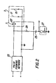
- FIG. 2 shows an embodiment of the arc circuit 9.
- This circuit comprises a pulse forming network 23 which is connected to the cathode 7.
- Capacitor 25 is charged to a high positive potential with respect to ground.
- a triggered spark gap circuit 27 (or other switching means (not shown)) is switched, capacitor 25 reverses polarity and a high negative potential is applied to the cathode which causes a breakdown across the gap between the cathode and the trigger electrode.
- This voltage breakdown results in the initiation of a vacuum arc which creates the plasma that rotates within the plasma centrifuge.
- Resistor 29 is important in that without this resistor, the pulse forming network will not discharge in spite of the break down between the cathode and the electrode. The reason for this is that without resistor 29, during the trigger pulse, the cathode 7 remains at a negative potential higher than that of the pulse forming network preventing the flow of current from the pulse forming network.
- FIG 3 is a more detailed schematic circuit diagram of the arc circuit shown in Figure 2.
- the pulse forming network 23 is charged by means of a transformer 77 and rectifier 79.
- the coil 81 of a normally closed relay is deenergized and switch 83 is closed thereby providing a discharge path for the pulse forming network 23 through a bleeding resistor 85.
- the magnetic coils 5, which supply the magnetic field for the plasma centrifuge, receive power from a transformer 87.
- the field current is periodically applied by the closing of a microswitch 89, which is closed by a cam 91 on a cam wheel 93, rotated by a synchronous motor (not shown).
- the trigger circuit 27 includes a high voltage supply comprising a transformer 95 and a rectifier unit 97.
- the rectified voltage from the rectifier unit 97 charges the capacitor 25 and at the same time, cam switch 99 is closed by the rotation of the cam wheel 93.
- cam switch 99 is closed by the rotation of the cam wheel 93.
- capacitor 101 is discharged into the primary of pulse transformer 103.
- the secondary of the transformer 103 is connected to the trigger electrode of a triggered spark gap 105, which has one terminal connected to capacitor 25, which was previously charged to a high positive potential. Since the capacitor cannot discharge immediately, its terminal, which was at ground potential jumps to a high negative potential, thereby placing a high negative potential on the cathode 7 of the vacuum arc.
- the capacitor 25 discharges through the gap 107 between the vacuum arc cathode 7 and the trigger electrode 109, producing a spark which initiates the vacuum arc.
- the pulse forming network then discharges into the vacuum arc to form the plasma of a completely ionized gas.
- Figure 4A illustrates a pulse forming network having a resistance which is less than the impedance of the load. Examples of the values of the inductors and capacitors in the pulse forming network are as shown in Figure 4B.
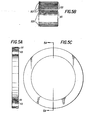
- the internal resistances of the inductors represented by R1-R5 in Figure 4A, are maintained as low as possible by use of copper strip inductors, for example, such as shown in Figure 5.
- the inductors L1-L5 are formed from copper strips as shown in Figures 5A-5C. Each of the inductors are wound from copper strips 111 with mylar insulation strips 113 therebetween. The coils are wound in the form of a helix as shown in Figures 5A and C. Figure; 5B is an enlarged section of the coil layers.
- the copper strip has a thickness of 0.6 millimeters and a width of 40 millimeters.
- 20 turns are necessary and the ohmic resistance of the inductor (at 20"C) is 5 milliohms.
- the inductor coil has an inner diameter of 18 centimeters.
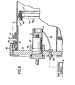
- Figures 6 and 7 illustrate the structure for connecting the arc initiation circuit to the cathode and the holder for the grid anode.
- the cathode 7 is fitted within a quartz tube 43 which is in turn held by a holder member 45.
- a plate 47 of a material such as lucite has the holder 45 mounted therethrough and the plate 47 is connected to the vessel 3 by means of a release nut 48 and a threaded member 49 which is fixed to the vessel 3 by means of a flange 51 and bolt 53.
- a connector 55 passes through the plate 47 for connecting the arc circuit 9 to the trigger electrode 11 through connector 57.
- the anode grid 17 is held in place by a grid holder 59 shown in Figures 6 and 7.
- the grid holder holds the grid 17 within the vessel 3 of the plasma centrifuge.
- the grid holder comprises a ring 61 having a knife edge. 67 at its largest diameter which is approximately equal to the inner diameter of the vessel 3.
- the ring 61 has a plurality of radial slits 63 distributed around the ring. The tightening of the bolts 65 causes a deformation of the ring in such a way that the diameter increases at certain points causing the knife edge 67 to "bite into” the inner surface of the vessel 3.
- the grid 1.7 is used to stabilize the vacuum arc and to prevent the initiation of the arc in a backwards direction as a sliding spark along the cathode holder.
- the grid serves as an anode because of the large Debye length in the plasma as compared to the diameter of holes in the grid, and the grid appears to the discharge as a solid plate.
- the plasma density is high and the Debye length is short and thus, the grid behaves as a Langmuir probe collecting only a small current in comparison to the arc current.
- FIG 8 illustrates an alternative embodiment of the cathode and electrode structure of the present invention.
- the cathode has a body 67, a portion of which 69 is formed from the material which forms the plasma which is the material to be separated.
- the body 67 and portion 69 have an axial hole 71 which extends therethrough.
- the electrode 73 is coaxial with the body 67 and is positioned in the hole 71.
- a quartz insulator 75 insulates the electrode from the cathode.
- the cathode is held in the vessel in the same manner as the embodiment shown in Figure 6.
Landscapes
- Chemical & Material Sciences (AREA)
- Chemical Kinetics & Catalysis (AREA)
- Analytical Chemistry (AREA)
- Plasma Technology (AREA)
Applications Claiming Priority (2)
| Application Number | Priority Date | Filing Date | Title |
|---|---|---|---|
| US06/564,532 US4612477A (en) | 1983-12-22 | 1983-12-22 | Triggering device for a vacuum arc in a plasma centrifuge |
| US564532 | 1983-12-22 |
Publications (2)
| Publication Number | Publication Date |
|---|---|
| EP0147079A2 true EP0147079A2 (de) | 1985-07-03 |
| EP0147079A3 EP0147079A3 (de) | 1987-09-02 |
Family
ID=24254854
Family Applications (1)
| Application Number | Title | Priority Date | Filing Date |
|---|---|---|---|
| EP84308283A Withdrawn EP0147079A3 (de) | 1983-12-22 | 1984-11-29 | Triggervorrichtung für einen Vakuumbogen in einer Plasmazentrifuge |
Country Status (4)
| Country | Link |
|---|---|
| US (1) | US4612477A (de) |
| EP (1) | EP0147079A3 (de) |
| JP (1) | JPS60157200A (de) |
| IL (1) | IL73531A0 (de) |
Families Citing this family (10)
| Publication number | Priority date | Publication date | Assignee | Title |
|---|---|---|---|---|
| GB8601099D0 (en) * | 1986-01-17 | 1986-02-19 | British Aerospace | Pulse-forming networks |
| US4766351A (en) * | 1987-06-29 | 1988-08-23 | Hull Donald E | Starter for inductively coupled plasma tube |
| JP2700280B2 (ja) * | 1991-03-28 | 1998-01-19 | 理化学研究所 | イオンビーム発生装置および成膜装置および成膜方法 |
| US5896012A (en) * | 1997-08-08 | 1999-04-20 | Kabushiki Kaisha Kobe Seiko Sho | Metal ion plasma generator having magnetic field forming device located such that a triggering is between the magnetic field forming device and an anode |
| US6331701B1 (en) * | 1998-05-20 | 2001-12-18 | Lee Chen | RF-grounded sub-Debye neutralizer grid |
| CA2241116C (en) | 1998-06-19 | 2009-08-25 | Liyan Zhang | Radiation (e.g. x-ray pulse) generator mechanisms |
| US6512333B2 (en) | 1999-05-20 | 2003-01-28 | Lee Chen | RF-powered plasma accelerator/homogenizer |
| DE10010126C2 (de) * | 2000-03-03 | 2002-10-10 | Cobes Gmbh Nachrichten Und Dat | Verfahren und Vorrichtung zum Plasmabehandeln der Oberfläche von Substraten durch Ionenbeschuß |
| SE0401780D0 (sv) * | 2004-07-02 | 2004-07-02 | Scandinova Ab | Skyddskrets |
| US7502446B2 (en) * | 2005-10-18 | 2009-03-10 | Alft Inc. | Soft x-ray generator |
Family Cites Families (7)
| Publication number | Priority date | Publication date | Assignee | Title |
|---|---|---|---|---|
| GB606446A (en) * | 1943-12-20 | 1948-08-13 | Marconi Wireless Telegraph Co | Electrical pulse generator |
| US3071710A (en) * | 1960-05-26 | 1963-01-01 | Fischer Heinz | Coaxial transmission line with spaced capacitance control of pulse generation |
| US3836451A (en) * | 1968-12-26 | 1974-09-17 | A Snaper | Arc deposition apparatus |
| US3809896A (en) * | 1971-05-25 | 1974-05-07 | Varian Mat Gmbh | Method for the mass spectrometric analysis of solids |
| US4092559A (en) * | 1975-06-20 | 1978-05-30 | Pavel Nikanorovich Dashuk | Controlled discharger |
| US4275317A (en) * | 1979-03-23 | 1981-06-23 | Nasa | Pulse switching for high energy lasers |
| US4458180A (en) * | 1982-02-18 | 1984-07-03 | Elscint Ltd. | Plasma electron source for cold-cathode discharge device or the like |
-
1983
- 1983-12-22 US US06/564,532 patent/US4612477A/en not_active Expired - Fee Related
-
1984
- 1984-11-16 IL IL73531A patent/IL73531A0/xx unknown
- 1984-11-29 EP EP84308283A patent/EP0147079A3/de not_active Withdrawn
- 1984-12-04 JP JP59257277A patent/JPS60157200A/ja active Pending
Also Published As
| Publication number | Publication date |
|---|---|
| JPS60157200A (ja) | 1985-08-17 |
| IL73531A0 (en) | 1985-02-28 |
| EP0147079A3 (de) | 1987-09-02 |
| US4612477A (en) | 1986-09-16 |
Similar Documents
| Publication | Publication Date | Title |
|---|---|---|
| EP0417649B1 (de) | Plasma-Schalter mit hohler, thermoionischer Kathode | |
| US3970884A (en) | Portable X-ray device | |
| US5191517A (en) | Electrostatic particle accelerator having linear axial and radial fields | |
| US4612477A (en) | Triggering device for a vacuum arc in a plasma centrifuge | |
| JPH01502568A (ja) | 金属の磁気パルス加工および溶接用の放電装置 | |
| US3714510A (en) | Method and apparatus for ignition of crossed field switching device for use in a hvdc circuit breaker | |
| US6965629B2 (en) | Method and apparatus for initiating a pulsed arc discharge for nanopowder synthesis | |
| EP1316101A1 (de) | Spannungsreduktionsmittel für linearstrahlvorrichtung mit vorgespanntem mehrstuffenkollektor | |
| US3681604A (en) | Portable x-ray generating machine | |
| US7166853B2 (en) | Active method and system of establishing electrical contact | |
| Gilmour et al. | The interruption of vacuum arcs at high DC voltages | |
| JPH06215700A (ja) | コンパクトな高電流交差電界プラズマスイッチ | |
| US4092559A (en) | Controlled discharger | |
| Kanaeva et al. | A high-voltage pulse generator for electric-discharge technologies | |
| JP3881091B2 (ja) | パルス発生器 | |
| US3944887A (en) | Crowbar switch | |
| US3735195A (en) | Spark-discharge apparatus for electrohydraulic crushing | |
| RU2810296C1 (ru) | Высоковольтный импульсный источник | |
| US20080006521A1 (en) | Method for initiating a pulsed arc discharge for nanopowder synthesis | |
| Bieniosek et al. | MEDEA II two‐pulse generator development | |
| RU2169442C1 (ru) | Индуктивный генератор | |
| JPH0650110B2 (ja) | Rf型イオン源 | |
| Kemp | Elements of energy storage capacitor banks | |
| JP3766571B2 (ja) | 薄膜形成装置及びシャンティングアーク放電電極装置 | |
| Burgess | Fast Capacitor Bank for Pulsed Magnetic-Field Studies |
Legal Events
| Date | Code | Title | Description |
|---|---|---|---|
| PUAI | Public reference made under article 153(3) epc to a published international application that has entered the european phase |
Free format text: ORIGINAL CODE: 0009012 |
|
| AK | Designated contracting states |
Designated state(s): AT BE CH DE FR GB IT LI NL SE |
|
| PUAL | Search report despatched |
Free format text: ORIGINAL CODE: 0009013 |
|
| AK | Designated contracting states |
Kind code of ref document: A3 Designated state(s): AT BE CH DE FR GB IT LI NL SE |
|
| STAA | Information on the status of an ep patent application or granted ep patent |
Free format text: STATUS: THE APPLICATION IS DEEMED TO BE WITHDRAWN |
|
| 18D | Application deemed to be withdrawn |
Effective date: 19880303 |
|
| RIN1 | Information on inventor provided before grant (corrected) |
Inventor name: DOTHAN, FELIX |