EP0147254B1 - Témoin de fatigue - Google Patents
Témoin de fatigue Download PDFInfo
- Publication number
- EP0147254B1 EP0147254B1 EP84402187A EP84402187A EP0147254B1 EP 0147254 B1 EP0147254 B1 EP 0147254B1 EP 84402187 A EP84402187 A EP 84402187A EP 84402187 A EP84402187 A EP 84402187A EP 0147254 B1 EP0147254 B1 EP 0147254B1
- Authority
- EP
- European Patent Office
- Prior art keywords
- web
- plane
- slit
- thin
- elements
- Prior art date
- Legal status (The legal status is an assumption and is not a legal conclusion. Google has not performed a legal analysis and makes no representation as to the accuracy of the status listed.)
- Expired
Links
- 238000010008 shearing Methods 0.000 claims abstract description 3
- 238000006073 displacement reaction Methods 0.000 description 7
- 238000010586 diagram Methods 0.000 description 1
- 229910001234 light alloy Inorganic materials 0.000 description 1
Images

Classifications
-
- G—PHYSICS
- G01—MEASURING; TESTING
- G01L—MEASURING FORCE, STRESS, TORQUE, WORK, MECHANICAL POWER, MECHANICAL EFFICIENCY, OR FLUID PRESSURE
- G01L1/00—Measuring force or stress, in general
- G01L1/06—Measuring force or stress, in general by measuring the permanent deformation of gauges, e.g. of compressed bodies
-
- G—PHYSICS
- G01—MEASURING; TESTING
- G01B—MEASURING LENGTH, THICKNESS OR SIMILAR LINEAR DIMENSIONS; MEASURING ANGLES; MEASURING AREAS; MEASURING IRREGULARITIES OF SURFACES OR CONTOURS
- G01B5/00—Measuring arrangements characterised by the use of mechanical techniques
- G01B5/30—Measuring arrangements characterised by the use of mechanical techniques for measuring the deformation in a solid, e.g. mechanical strain gauge
-
- G—PHYSICS
- G01—MEASURING; TESTING
- G01N—INVESTIGATING OR ANALYSING MATERIALS BY DETERMINING THEIR CHEMICAL OR PHYSICAL PROPERTIES
- G01N3/00—Investigating strength properties of solid materials by application of mechanical stress
- G01N3/02—Details
- G01N3/06—Special adaptations of indicating or recording means
Definitions
- the present invention relates to a fatigue indicator for a mechanical part subjected to repeated efforts, which comprises two thick elements spaced from one another and joined to one another by a thin veil provided with a slot, these two elements being incorporated into the part or fixed to it so as to move relative to each other in a plane which is parallel to the plane of the web.
- European patents 0032101 and 0090730 describe fatigue indicators of this kind in which the thick elements are arranged so as to be separated from one another in a direction substantially perpendicular to their direction of relative movement when the part is working, thin veil thus being subjected to a shearing force in its plane and in that the slit of the thin veil extends from one of the edges of the veil in said direction of relative movement, so that, when the part is working, two cracks appear from the ends of the bottom of the slit, gradually extend into the veil, and eventually reach the opposite edge of the veil or join cracks from this opposite edge, the central area of the veil thus being detached or almost detached .
- This indicator is mainly intended to indicate the fatigue of a part subjected to tensile or compressive forces.
- the relative displacement of these two thick elements is equal to the relative displacement of the two places of the part on which they are fixed. This last movement is a datum that depends on the part and whose value cannot be modified. However, it may be, in particular in the case of light alloy parts, that this value is incompatible with the characteristics of the fatigue indicator.
- the subject of the present invention is an improvement made to the fatigue indicator of the above type with the aim of remedying this difficulty.
- the thick elements are connected at each of their ends by a flexible zone to the same part which is itself connected by a flexible zone to a fixing part on the part to be monitored.
- the parts between the flexible zones form levers and the value of the relative displacement of the thick elements is equal to the value of the displacement of the fixing parts multiplied by a coefficient depending on the distances from the flexible zones to the longitudinal axis of the fatigue indicator.
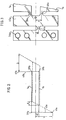
- the witness comprises two thick parts 1a and 1b spaced from one another and connected to each other by several thin webs 2 'of which only one is shown; each of these sails has two slots 4a and 4b parallel to the longitudinal direction of the parts 1a and 1b, the bottom of each of these slots comprising a tab 27a or 27b which is raised outside the plane of the veil, one of 'one side of this plane and the other on the opposite side; these tabs are used for the attachment of springs 28a and 28b.
- Parts 1a and 1b are further connected by flexible bridges 38 disposed between two adjacent thin webs.
- the parts 1a and 1b are connected by flexible zones 39a or 39b to the same portion 40a or 40b which is itself connected by a flexible zone 41a or 41b to a part 36a or 36b serving to fixing the fatigue indicator on the part to be monitored.
- the two flexible zones 39a are arranged substantially symmetrically with respect to the median longitudinal axis X-X of the fatigue indicator and are each spaced from this axis by a distance a. The same is true of the flexible zones 39b.
- the flexible zones 41a and 41b are arranged one on one side of the axis X-X and the other on the opposite side. Each of them is spaced transversely from the axis X-X by a distance b which is here greater than a.
- the flexible zones 41 a and 41 are distant from the axis X-X by a distance b less than a.
- the two fixing pieces 36a and 36b move longitudinally relative to each other by a distance D
- the two thick parts 1a and 1b move relative to each other d 'a distance d greater than D.
Landscapes
- General Physics & Mathematics (AREA)
- Physics & Mathematics (AREA)
- Health & Medical Sciences (AREA)
- Life Sciences & Earth Sciences (AREA)
- Chemical & Material Sciences (AREA)
- Analytical Chemistry (AREA)
- Biochemistry (AREA)
- General Health & Medical Sciences (AREA)
- Immunology (AREA)
- Pathology (AREA)
- Investigating Strength Of Materials By Application Of Mechanical Stress (AREA)
- Control And Other Processes For Unpacking Of Materials (AREA)
- Dental Preparations (AREA)
- Confectionery (AREA)
- Pharmaceuticals Containing Other Organic And Inorganic Compounds (AREA)
- Processing And Handling Of Plastics And Other Materials For Molding In General (AREA)
- Processing Of Solid Wastes (AREA)
- Instrument Panels (AREA)
- Investigating Or Analysing Materials By The Use Of Chemical Reactions (AREA)
- Road Signs Or Road Markings (AREA)
- Materials For Medical Uses (AREA)
- Heat Treatment Of Steel (AREA)
Description
- La présente invention concerne un témoin de fatigue pour pièce mécanique soumis à des efforts répétés, qui comporte deux éléments épais écartés l'un de l'autre et réunis l'un à l'autre par un voile mince muni d'une fente, ces deux éléments étant incorporés à la pièce ou fixés à celle-ci de manière à se déplacer l'un par rapport à l'autre dans un plan qui est parallèle au plan du voile.
- Les brevets européens 0032101 et 0090730 décrivent des témoins de fatigue de ce genre dans lesquels les éléments épais sont disposés de manière à être écartés l'un de l'autre dans une direction sensiblement perpendiculaire à leur direction de déplacement relatif lorsque la pièce travaille, le voile mince étant ainsi soumis à un effort de cisaillement dans son plan et en ce que la fente du voile mince s'étend depuis l'un des bords du voile dans ladite direction de déplacement relatif, de sorte que, lorsque la pièce travaille, deux fissures apparaissent à partir des extrémités du fond de la fente, s'étendent progressivement dans le voile, et finissent par atteindre le bord opposé du voile ou rejoindre des fissures issues de ce bord opposé, la zone centrale du voile étant ainsi détachée ou quasiment détachée.
- Ce témoin est destiné essentiellement à indiquer la fatigue d'une pièce soumise à des efforts de traction ou de compression. Lorsque les éléments épais du témoin de fatigue sont directement fixés sur la pièce à surveiller, le déplacement relatif de ces deux éléments épais est égal au déplacement relatif des deux endroits de la pièce sur lesquels ils sont fixés. Ce dernier déplacement est une donnée que dépend de la pièce et dont la valeur ne peut être modifiée. Or, il se peut, en particulier dans le cas de pièces en alliage léger que cette valeur soit incompatible avec les caractéristiques du témoin de fatigue.
- La présente invention a pour objet un perfectionnement apporté au témoin de fatigue de type ci-dessus dans le but de remédier à cette difficulté.
- Selon la présente invention, les éléments épais sont reliés à chacune de leurs extrémités par une zone flexible à une même partie qui est elle-même reliée par une zone flexible à une partie de fixation sur la pièce à surveiller.
- Lorsque les deux parties de fixation sur la pièce se déplacent l'une par rapport à l'autre, les parties comprises entre les zones flexibles forment leviers et la valeur du déplacement relatif des éléments épais est égale à la valeur du déplacement des parties de fixation multipliée par un coefficient fonction des distances des zones flexibles à l'axe longitudinal du témoin de fatigue. En choisissant convenablement l'emplacement de ces zones flexibles, on peut à volonté diminuer la valeur du déplacement des éléments épais ou au contraire l'augmenter.
- On a décrit ci-après, à titre d'exemple non limitatif, un mode de réalisation du témoin de fatigue selon la présente invention, avec référence au dessin annexé dans lequel:
- La fig. 1 est une vue en plan de ce mode de réalisation;
- la fig. 2 est un schéma de ce mode de réalisation montrant le déplacement des différentes parties du témoin de fatigue;
- la fig. 3 est un détail d'une variante.
- A la fig. 1 le témoin comporte deux parties épaisses 1a et 1b écartées l'une de l'autre et reliées l'une à l'autre par plusieurs voiles minces 2' dont un seul est représenté; chacun de ces voiles présente deux fentes 4a et 4b parallèles à la direction longitudinale des parties 1a et 1b, le fond de chacune de ces fentes comportant une patte 27a ou 27b qui est relevée à l'extérieur du plan du voile, l'une d'un côté de ce plan et l'autre du côté opposé; ces pattes servent à l'accrochage de ressorts 28a et 28b. Les parties 1 a et 1 b sont en outre reliées par des ponts flexibles 38 disposés entre deux voiles minces adjacents..
- A chacune de leurs extrémités, les pièces 1a et 1 b sont reliées par des zones flexibles 39a ou 39b à une même portion 40a ou 40b qui est elle-même reliée par une zone flexible 41a ou 41 b à une partie 36a ou 36b servant à la fixation du témoin de fatigue sur la pièce à surveiller.
- Les deux zones flexibles 39a sont disposées sensiblement symétriquement par rapport à l'axe longitudinal médian X-X du témoin de fatigue et sont écartées chacune de cet axe d'une distance a. Il en est de même des zones flexibles 39b.
- Les zones flexibles 41a et 41b sont disposées l'une d'un côté de l'axe X-X et l'autre du côté opposé. Chacune d'elles est écartée transversalement de l'axe X-X d'une distance b qui est ici supérieure à a.
- On constate à la fig. 2 que, lorsque les deux pièces de fixation 36a et 36b, c'est-à-dire les endroits de la structure à surveiller sur lesquels ces pièces sont fixées, s'écartent ou se rapprochent l'une de l'autre d'une distance D, les deux parties épaisses 1 a et 1 b se déplacent l'une par rapport à l'autre d'une distance d plus faible que D. On voit facilement que l'on a:

- Dans la disposition de la fig. 3, les zones flexibles 41 a et 41 sont éloignées de l'axe X-X d'une distance b inférieure à a. Dans ce das, lorsque les deux pièces de fixation 36a et 36b se déplacent longitudinalement l'une par rapport à l'autre d'une distance D, les deux parties épaisses 1a et 1b se déplacent l'une par rapport à l'autre d'une distance d supérieure à D.
- On voit ainsi qu'en choisissant convenablement le rapport a/b, on peut obtenir des valeurs de déplacement convenables pour les parties épaisses 1a et 1 b, quelles que soient les distances dont se déplacent les pièces de fixation 36a et 36b, donc les endroits de la structure à surveiller où sont fixées ces pièces.
Claims (1)
Priority Applications (1)
| Application Number | Priority Date | Filing Date | Title |
|---|---|---|---|
| AT84402187T ATE31820T1 (de) | 1983-11-04 | 1984-10-31 | Vorrichtung zum anzeigen von materialermuedung. |
Applications Claiming Priority (2)
| Application Number | Priority Date | Filing Date | Title |
|---|---|---|---|
| FR8318059A FR2554591B2 (fr) | 1980-01-03 | 1983-11-04 | Temoin de fatigue |
| FR8318059 | 1983-11-04 |
Publications (2)
| Publication Number | Publication Date |
|---|---|
| EP0147254A1 EP0147254A1 (fr) | 1985-07-03 |
| EP0147254B1 true EP0147254B1 (fr) | 1988-01-07 |
Family
ID=9294073
Family Applications (1)
| Application Number | Title | Priority Date | Filing Date |
|---|---|---|---|
| EP84402187A Expired EP0147254B1 (fr) | 1983-11-04 | 1984-10-31 | Témoin de fatigue |
Country Status (9)
| Country | Link |
|---|---|
| US (1) | US4580520A (fr) |
| EP (1) | EP0147254B1 (fr) |
| JP (1) | JPS60209138A (fr) |
| AT (1) | ATE31820T1 (fr) |
| AU (1) | AU567773B2 (fr) |
| BR (1) | BR8405573A (fr) |
| CA (1) | CA1232471A (fr) |
| DE (1) | DE3468531D1 (fr) |
| NO (1) | NO160552C (fr) |
Families Citing this family (8)
| Publication number | Priority date | Publication date | Assignee | Title |
|---|---|---|---|---|
| GB2223855B (en) * | 1988-10-14 | 1992-04-01 | Nicholas John Prescott | Fatigue monitoring |
| JP3020162B1 (ja) * | 1998-12-17 | 2000-03-15 | 広島大学長 | 構造物の長期応力度モニタリングのための犠牲試験片及びその使用方法 |
| US6983660B2 (en) | 2003-04-29 | 2006-01-10 | Young Wuk Kwon | Fatigue measurement device and method |
| USD540701S1 (en) * | 2005-06-09 | 2007-04-17 | Miller Stephen A | Limited access chain or belt tension checking device |
| EP2526372A1 (fr) * | 2010-03-12 | 2012-11-28 | Siemens Aktiengesellschaft | Appareil indicateur pour paroi de tour d'éolienne |
| KR101481199B1 (ko) * | 2010-12-13 | 2015-01-12 | 현대중공업 주식회사 | 피로도 표시기를 구비한 굴삭기 |
| CN104062193B (zh) * | 2014-06-30 | 2016-03-30 | 长安大学 | 钢桥水平节点板处的腹板间隙面外变形疲劳试验加载装置 |
| US12295890B2 (en) * | 2020-12-28 | 2025-05-13 | GE Precision Healthcare LLC | Infant care device including predictive failure side panels |
Family Cites Families (4)
| Publication number | Priority date | Publication date | Assignee | Title |
|---|---|---|---|---|
| US3572091A (en) * | 1968-09-27 | 1971-03-23 | Keith H Mcfarland | Mechanical strain indicator |
| JPS56142439A (en) * | 1980-01-03 | 1981-11-06 | Esu Tee Aa Esu Soc Tech Dasets | Fatigue stress indicator |
| AU559262B2 (en) * | 1982-03-30 | 1987-03-05 | S.T.A.S. Societe Technique D'accessoires Specialises | Fatigue strew indicator |
| FR2524642A2 (fr) * | 1982-03-30 | 1983-10-07 | Stas Soc Tech Access Spec | Temoin de fatigue |
-
1983
- 1983-11-02 AU AU34960/84A patent/AU567773B2/en not_active Ceased
-
1984
- 1984-10-23 CA CA000466130A patent/CA1232471A/fr not_active Expired
- 1984-10-30 JP JP59228825A patent/JPS60209138A/ja active Pending
- 1984-10-31 EP EP84402187A patent/EP0147254B1/fr not_active Expired
- 1984-10-31 BR BR8405573A patent/BR8405573A/pt unknown
- 1984-10-31 AT AT84402187T patent/ATE31820T1/de not_active IP Right Cessation
- 1984-10-31 DE DE8484402187T patent/DE3468531D1/de not_active Expired
- 1984-11-01 NO NO844338A patent/NO160552C/no unknown
- 1984-11-01 US US06/667,262 patent/US4580520A/en not_active Expired - Fee Related
Also Published As
| Publication number | Publication date |
|---|---|
| EP0147254A1 (fr) | 1985-07-03 |
| AU567773B2 (en) | 1987-12-03 |
| NO844338L (no) | 1985-05-06 |
| CA1232471A (fr) | 1988-02-09 |
| AU3496084A (en) | 1985-05-09 |
| NO160552B (no) | 1989-01-16 |
| ATE31820T1 (de) | 1988-01-15 |
| BR8405573A (pt) | 1985-09-10 |
| JPS60209138A (ja) | 1985-10-21 |
| DE3468531D1 (en) | 1988-02-11 |
| US4580520A (en) | 1986-04-08 |
| NO160552C (no) | 1989-04-26 |
Similar Documents
| Publication | Publication Date | Title |
|---|---|---|
| EP0090730B1 (fr) | Témoin de fatigue | |
| CA2165899C (fr) | Chemin de cables en fils | |
| EP2659157B1 (fr) | Plot de friction souple et garniture de frein pourvue d'un tel plot | |
| EP0147254A1 (fr) | Témoin de fatigue | |
| EP0228931A1 (fr) | Ecran courbe, notamment écran de projection cinématographique | |
| FR2628804A1 (fr) | Amortisseur de vibrations de torsion | |
| FR2623583A2 (fr) | Supports elastiques | |
| EP1132645B1 (fr) | Dispositif élastique de suspension d'une structure vibrante à une structure rigide | |
| EP0305227A1 (fr) | Courroie trapézoidale perfectionnée | |
| FR3073201A1 (fr) | Procede de fabrication d'un rail de plancher d'aeronef obtenu par un assemblage par sertissage de deux parties, rail de plancher d'aeronef ainsi obtenu | |
| FR2554591A2 (fr) | Temoin de fatigue | |
| EP3309075A1 (fr) | Nacelle d'aeronef comprenant une liaison entre une entree d'air et une motorisation | |
| EP1348079B1 (fr) | Procede d'assemblage optimise de deux pieces sensiblement planes | |
| EP0323286A1 (fr) | Perfectionnements aux courroies de transmission de puissance | |
| EP1155894B1 (fr) | Support antivibratoire, et véhicule comportant un tel support | |
| FR3081367A1 (fr) | Procede d'assemblage par soudage d'au moins deux pieces en materiau composite et assemblage de pieces en materiau composite ainsi obtenu | |
| FR2563481A1 (fr) | Systeme d'essuie-glace pour vehicules a moteur | |
| EP0535628A1 (fr) | Dispositif de suspension à lames fléchissantes à grand débattement | |
| EP1195869A1 (fr) | Chemin de câbles en treillis soudé | |
| FR2645894A1 (fr) | Palissade en elements de profile | |
| EP3523151B1 (fr) | Cale allegee pour groupe motopropulseur apte a limiter des efforts transversaux | |
| FR3012416A1 (fr) | Aeronef comprenant une liaison souple deportee entre un moteur et une structure primaire de mat moteur | |
| FR2562852A1 (fr) | Systeme d'essuie-glace pour vehicules a moteur | |
| FR2689561A1 (fr) | Echelle à câbler. | |
| FR2559905A2 (fr) | Temoin de fatigue |
Legal Events
| Date | Code | Title | Description |
|---|---|---|---|
| PUAI | Public reference made under article 153(3) epc to a published international application that has entered the european phase |
Free format text: ORIGINAL CODE: 0009012 |
|
| AK | Designated contracting states |
Designated state(s): AT BE CH DE GB IT LI LU NL SE |
|
| 17P | Request for examination filed |
Effective date: 19850524 |
|
| 17Q | First examination report despatched |
Effective date: 19861023 |
|
| GRAA | (expected) grant |
Free format text: ORIGINAL CODE: 0009210 |
|
| AK | Designated contracting states |
Kind code of ref document: B1 Designated state(s): AT BE CH DE GB IT LI LU NL SE |
|
| REF | Corresponds to: |
Ref document number: 31820 Country of ref document: AT Date of ref document: 19880115 Kind code of ref document: T |
|
| ITF | It: translation for a ep patent filed | ||
| REF | Corresponds to: |
Ref document number: 3468531 Country of ref document: DE Date of ref document: 19880211 |
|
| GBT | Gb: translation of ep patent filed (gb section 77(6)(a)/1977) | ||
| PG25 | Lapsed in a contracting state [announced via postgrant information from national office to epo] |
Ref country code: LU Free format text: LAPSE BECAUSE OF NON-PAYMENT OF DUE FEES Effective date: 19881031 |
|
| PLBE | No opposition filed within time limit |
Free format text: ORIGINAL CODE: 0009261 |
|
| STAA | Information on the status of an ep patent application or granted ep patent |
Free format text: STATUS: NO OPPOSITION FILED WITHIN TIME LIMIT |
|
| 26N | No opposition filed | ||
| PGFP | Annual fee paid to national office [announced via postgrant information from national office to epo] |
Ref country code: BE Payment date: 19891004 Year of fee payment: 6 |
|
| PGFP | Annual fee paid to national office [announced via postgrant information from national office to epo] |
Ref country code: SE Payment date: 19891019 Year of fee payment: 6 |
|
| ITTA | It: last paid annual fee | ||
| PG25 | Lapsed in a contracting state [announced via postgrant information from national office to epo] |
Ref country code: AT Effective date: 19891031 |
|
| PGFP | Annual fee paid to national office [announced via postgrant information from national office to epo] |
Ref country code: CH Payment date: 19900126 Year of fee payment: 6 |
|
| PG25 | Lapsed in a contracting state [announced via postgrant information from national office to epo] |
Ref country code: LI Effective date: 19901031 Ref country code: CH Effective date: 19901031 Ref country code: BE Effective date: 19901031 |
|
| PG25 | Lapsed in a contracting state [announced via postgrant information from national office to epo] |
Ref country code: SE Effective date: 19901101 |
|
| BERE | Be: lapsed |
Owner name: S.A. STAS SOC. TECHNIQUE D'ACCESSOIRES SPECIALISE Effective date: 19901031 |
|
| REG | Reference to a national code |
Ref country code: CH Ref legal event code: PL |
|
| PGFP | Annual fee paid to national office [announced via postgrant information from national office to epo] |
Ref country code: NL Payment date: 19911031 Year of fee payment: 8 |
|
| PG25 | Lapsed in a contracting state [announced via postgrant information from national office to epo] |
Ref country code: NL Effective date: 19930501 |
|
| NLV4 | Nl: lapsed or anulled due to non-payment of the annual fee | ||
| EUG | Se: european patent has lapsed |
Ref document number: 84402187.3 Effective date: 19910705 |
|
| PGFP | Annual fee paid to national office [announced via postgrant information from national office to epo] |
Ref country code: GB Payment date: 19961025 Year of fee payment: 13 |
|
| PGFP | Annual fee paid to national office [announced via postgrant information from national office to epo] |
Ref country code: DE Payment date: 19961122 Year of fee payment: 13 |
|
| PG25 | Lapsed in a contracting state [announced via postgrant information from national office to epo] |
Ref country code: GB Free format text: LAPSE BECAUSE OF NON-PAYMENT OF DUE FEES Effective date: 19971031 |
|
| GBPC | Gb: european patent ceased through non-payment of renewal fee |
Effective date: 19971031 |
|
| PG25 | Lapsed in a contracting state [announced via postgrant information from national office to epo] |
Ref country code: DE Free format text: LAPSE BECAUSE OF NON-PAYMENT OF DUE FEES Effective date: 19980701 |