EP0147835A2 - Lichtstrahlabtastvorrichtung - Google Patents
Lichtstrahlabtastvorrichtung Download PDFInfo
- Publication number
- EP0147835A2 EP0147835A2 EP84116143A EP84116143A EP0147835A2 EP 0147835 A2 EP0147835 A2 EP 0147835A2 EP 84116143 A EP84116143 A EP 84116143A EP 84116143 A EP84116143 A EP 84116143A EP 0147835 A2 EP0147835 A2 EP 0147835A2
- Authority
- EP
- European Patent Office
- Prior art keywords
- scanning
- pulse
- light beam
- photodetector
- output
- Prior art date
- Legal status (The legal status is an assumption and is not a legal conclusion. Google has not performed a legal analysis and makes no representation as to the accuracy of the status listed.)
- Granted
Links
Images


Classifications
-
- H—ELECTRICITY
- H04—ELECTRIC COMMUNICATION TECHNIQUE
- H04N—PICTORIAL COMMUNICATION, e.g. TELEVISION
- H04N1/00—Scanning, transmission or reproduction of documents or the like, e.g. facsimile transmission; Details thereof
- H04N1/04—Scanning arrangements, i.e. arrangements for the displacement of active reading or reproducing elements relative to the original or reproducing medium, or vice versa
- H04N1/047—Detection, control or error compensation of scanning velocity or position
- H04N1/053—Detection, control or error compensation of scanning velocity or position in main scanning direction, e.g. synchronisation of line start or picture elements in a line
-
- H—ELECTRICITY
- H04—ELECTRIC COMMUNICATION TECHNIQUE
- H04N—PICTORIAL COMMUNICATION, e.g. TELEVISION
- H04N1/00—Scanning, transmission or reproduction of documents or the like, e.g. facsimile transmission; Details thereof
- H04N1/04—Scanning arrangements, i.e. arrangements for the displacement of active reading or reproducing elements relative to the original or reproducing medium, or vice versa
- H04N1/113—Scanning arrangements, i.e. arrangements for the displacement of active reading or reproducing elements relative to the original or reproducing medium, or vice versa using oscillating or rotating mirrors
- H04N1/1135—Scanning arrangements, i.e. arrangements for the displacement of active reading or reproducing elements relative to the original or reproducing medium, or vice versa using oscillating or rotating mirrors for the main-scan only
-
- H—ELECTRICITY
- H04—ELECTRIC COMMUNICATION TECHNIQUE
- H04N—PICTORIAL COMMUNICATION, e.g. TELEVISION
- H04N1/00—Scanning, transmission or reproduction of documents or the like, e.g. facsimile transmission; Details thereof
- H04N1/04—Scanning arrangements, i.e. arrangements for the displacement of active reading or reproducing elements relative to the original or reproducing medium, or vice versa
- H04N1/12—Scanning arrangements, i.e. arrangements for the displacement of active reading or reproducing elements relative to the original or reproducing medium, or vice versa using the sheet-feed movement or the medium-advance or the drum-rotation movement as the slow scanning component, e.g. arrangements for the main-scanning
-
- H—ELECTRICITY
- H04—ELECTRIC COMMUNICATION TECHNIQUE
- H04N—PICTORIAL COMMUNICATION, e.g. TELEVISION
- H04N2201/00—Indexing scheme relating to scanning, transmission or reproduction of documents or the like, and to details thereof
- H04N2201/024—Indexing scheme relating to scanning, transmission or reproduction of documents or the like, and to details thereof deleted
- H04N2201/02406—Arrangements for positioning elements within a head
- H04N2201/02439—Positioning method
-
- H—ELECTRICITY
- H04—ELECTRIC COMMUNICATION TECHNIQUE
- H04N—PICTORIAL COMMUNICATION, e.g. TELEVISION
- H04N2201/00—Indexing scheme relating to scanning, transmission or reproduction of documents or the like, and to details thereof
- H04N2201/04—Scanning arrangements
- H04N2201/047—Detection, control or error compensation of scanning velocity or position
- H04N2201/04701—Detection of scanning velocity or position
- H04N2201/0471—Detection of scanning velocity or position using dedicated detectors
-
- H—ELECTRICITY
- H04—ELECTRIC COMMUNICATION TECHNIQUE
- H04N—PICTORIAL COMMUNICATION, e.g. TELEVISION
- H04N2201/00—Indexing scheme relating to scanning, transmission or reproduction of documents or the like, and to details thereof
- H04N2201/04—Scanning arrangements
- H04N2201/047—Detection, control or error compensation of scanning velocity or position
- H04N2201/04701—Detection of scanning velocity or position
- H04N2201/04732—Detecting at infrequent intervals, e.g. once or twice per line for main-scan control
-
- H—ELECTRICITY
- H04—ELECTRIC COMMUNICATION TECHNIQUE
- H04N—PICTORIAL COMMUNICATION, e.g. TELEVISION
- H04N2201/00—Indexing scheme relating to scanning, transmission or reproduction of documents or the like, and to details thereof
- H04N2201/04—Scanning arrangements
- H04N2201/047—Detection, control or error compensation of scanning velocity or position
- H04N2201/04701—Detection of scanning velocity or position
- H04N2201/04744—Detection of scanning velocity or position by detecting the scanned beam or a reference beam
-
- H—ELECTRICITY
- H04—ELECTRIC COMMUNICATION TECHNIQUE
- H04N—PICTORIAL COMMUNICATION, e.g. TELEVISION
- H04N2201/00—Indexing scheme relating to scanning, transmission or reproduction of documents or the like, and to details thereof
- H04N2201/04—Scanning arrangements
- H04N2201/047—Detection, control or error compensation of scanning velocity or position
- H04N2201/04753—Control or error compensation of scanning position or velocity
- H04N2201/04755—Control or error compensation of scanning position or velocity by controlling the position or movement of a scanning element or carriage, e.g. of a polygonal mirror, of a drive motor
-
- H—ELECTRICITY
- H04—ELECTRIC COMMUNICATION TECHNIQUE
- H04N—PICTORIAL COMMUNICATION, e.g. TELEVISION
- H04N2201/00—Indexing scheme relating to scanning, transmission or reproduction of documents or the like, and to details thereof
- H04N2201/04—Scanning arrangements
- H04N2201/047—Detection, control or error compensation of scanning velocity or position
- H04N2201/04753—Control or error compensation of scanning position or velocity
- H04N2201/04794—Varying the control or compensation during the scan, e.g. using continuous feedback or from line to line
Definitions
- This invention relates to an apparatus for scanning with a light beam.
- This invention particularly relates to a light beam scanning apparatus used for reading out or recording an image.
- a light beam emitted by a laser beam source is reflected by a galvanometer mirror onto a recording medium so as to scan the recording medium in a main scanning direction and, at the same time, the recording medium is moved with respect to the light beam in a sub-scanning direction approximately normal to the main scanning direction by use of, for example, a mechanical feed means, thereby recording or reading out an image.
- image recording is conducted by modulating the light beam with an image signal by use of, for example, an acousto-optic modulator (AOM) and scanning the recording medium with the modulated light beam.
- AOM acousto-optic modulator
- the recording medium carrying the image recorded thereon is scanned by the light beam and light reflected by the recording medium or light transmitted therethrough is detected to read out the image recorded on the recording medium.
- the stimulable phosphor sheet is scanned by the light beam which, as stimulating rays, cause it to emit light in proportion to the radiation energy stored, and the emitted light is photoelectrically detected to read out the radiation image.
- scanning by the light beam should preferably be at a predetermined, constant scanning speed.
- the image can be recorded uniformly when the exposure time per picture element is maintained constant.
- the image read-out apparatus the image can be read out uniformly when the read-out time per picture element is constant.
- the light beam should preferably be scanned over a predetermined scanning range. That is, scanning in the main scanning direction should preferably be started from a predetermined initial position, thereby consistently conducting the image scanning.
- the optical system of the light beam scanning apparatus comprises many mechanically moveable elements such as a mirror and a galvanometer, it is not always possible to manually adjust the moveable elements to the optical condition and to maintain them in the optimal condition.
- the initial position offset of the scanning beam is greatly affected even by a slight error in the mirror alignment or in the position of the light source.
- the optical system is also adversely affected by a change in ambient temperature.
- the apparatus comprises a scanning means for scanning a light beam in accordance with a first signal, a grid having a plurality of optical gratings arrayed in the scanning direction of the light beam and generating a second signal as the light beam is scanned on the grating array, and a control means for generating the first signal on the basis of the second signal.
- the control means detects the speed at which the light beam is scanned on the basis of the second signal, adjusts the first signal on the basis of the detected speed, and controls the light beam scanning speed so that the detected speed is maintained equal to a predetermined speed.
- this apparatus it becomes possible to scan the light beam at a predetermined, constant scanning speed. For example, when the light beam scanning apparatus is applied to image recording, it becomes possible to record an image uniformly. When the apparatus is applied to image read-out, it becomes possible to read out an image uniformly.
- United States Patent_Application Ser. No. 543,558 filed on October 19, 1983 also proposes a light beam scanning apparatus comprising the aforesaid means wherein the control means detects the time required for the light beam to scan from a scanning start point to the end of the grating array on the basis of the second signal, and adjusts the initial level of the first signal on the basis of the detected time, thereby controlling the start point of scanning of the light beam.
- the control means detects the time required for the light beam to scan from a scanning start point to the end of the grating array on the basis of the second signal, and adjusts the initial level of the first signal on the basis of the detected time, thereby controlling the start point of scanning of the light beam.
- the control means detects the time required for the light beam to scan from a scanning start point to the end of the grating array on the basis of the second signal, and adjusts the initial level of the first signal on the basis of the detected time, thereby controlling the start point of scanning of the light beam.
- the aforesaid light beam scanning apparatus is disadvantageous in that, when ambient dust sticks to the surface of the grid, it becomes impossible to obtain a consistent synchronizing signal for controlling the light beam scanning from the grid.
- the primary object of the present invention is to provide a light beam scanning apparatus which can be fabricated at low cost and which is easy to operate.
- Another object of the present invention is to provide a light beam scanning apparatus wherein a synchronizing signal for controlling the scanning by a light beam is obtained consistently and the scanning by the light beam is adjusted to and maintained in a desired condition even when dust adheres to an element of the apparatus.
- the specific object of the present invention is to provide a light beam scanning apparatus wherein the initial position (start point) of scanning by a light beam is maintained at a predetermined position.
- the light beam scanning apparatus in accordance with the present invention is characterized by positioning two photodetectors such as photo transistors in spaced relation by a predetermined distance within a scanning region in a main scanning direction, detecting the start and the end of scanning in the main scanning direction by the photodetectors, and controlling the scanning speed of a main scanning means so that a predetermined number of pulses of a pulse signal having a predetermined period are input within the time between the start and the end of scanning in the main scanning direction.
- a scanned light beam is detected by use of two photodetectors positioned within the scanning region in the main scanning direction, and the scanning means is controlled so that the time of scanning by the light beam over the region between the two photodetectors is maintained constant. Therefore, it becomes possible to scan the light beam at a predetermined scanning speed. For example, when the light beam scanning apparatus is applied to image recording, it becomes possible to record an image uniformly. When the light beam scanning apparatus is applied to image read-out, it becomes possible to read out an image uniformly.
- the light beam scanning apparatus of the present invention there is no need to use expensive optical members as the light beam sensors, and two photodetectors such as photo transistors for generating a single pulse are used as the sensors. Therefore, the apparatus can be fabricated at a very low cost and is easy to operate. Further, the output pulses are obtained and no problem with regard to function arises even when some amount of dust or the like adheres to the light receiving faces of the photodetectors.
- two photodetectors are positioned, for example, outside of a material which should be scanned and adjacent the side end portions of the scanned material in the main scanning direction, and output pulses of the two photodetectors are received to obtain a square wave signal representing the scanning period, i.e. the time between the two pulses.
- the square wave signal is sent to a gate means, and a pulse signal having a predetermined period is further sent to the gate means.
- the pulses of the pulse signal which are sent from the gate means within the time corresponding to the scanning period are counted and the count is compared with a predetermined standard value. On the basis of the difference between the count and the standard value, the scanning speed of the main scanning means is controlled so that the light beam is always scanned at a predetermined speed.
- the present invention also provides a light beam scanning apparatus characterized by positioning a single photodetector such as a photo transistor within a scanning region in a main scanning direction, detecting the scanning time elapsing from the start of the scanning in the main scanning direction to the photodetector by use of the photodetector, and controlling the initial position of the scanning in the main scanning direction so that a predetermined number of pulses of a pulse signal having a predetermined period are input within the scanning time.
- a single photodetector such as a photo transistor
- the start point of the scanning in the main scanning direction is detected, a light beam scanned by the photodetector positioned within the scanning region in the main scanning direction is detected, and the initial position of the scanning.is controlled so that the time of scanning by the light beam over the region between the start point and the photodetector is maintained constant. Therefore, it becomes possible to scan the light beam from a predetermined initial position. For example, when the light beam scanning apparatus is applied to image recording, it becomes possible to record an image exactly in a predetermined region. When the light beam scanning apparatus is applied to image read-out, it becomes possible to exactly read out an image in the predetermined region.
- the light beam scanning apparatus of the present invention mentioned last, no expensive optical member need be used as the light beam sensor, and a single photodetector such as a photo transistor for generating a single pulse is used as the sensor. Therefore, the apparatus can be fabricated at a very low cost and is easy to operate. Further, the output pulse is obtained and no problem with regard to the function arises even when some amount of dust or the like adheres to the light receiving face of the photodetector.
- a square wave signal representing the scanning time from the start point of the scanning to the photodetector is obtained on the basis of, for example, an output signal of a means for detecting the initial position (start point) of the scanning in the main scanning direction and the output pulse of the photodetector positioned at an arbitrary position within the scanning range in the main scanning direction.
- the square wave signal is sent to a gate means, and a pulse signal having a predetermined period is further sent to the gate means.
- the pulses of the pulse signal which are sent from the gate means within the time corresponding to the scanning period are counted and the count is compared with a predetermined standard value.
- the scanning start point of the main scanning means is controlled so that the light beam is always scanned from a predetermined initial position.
- a square wave signal representing the scanning period and a pulse signal having a predetermined period generated by a pulse generating means are input to the gate means.
- the gate means outputs the pulses which are input thereto within the time corresponding to the scanning period (normally the high level period of the square wave signal).
- the gate means it is possible to use, for example, a two-input, one- output type TTL AND gate (74LS08 manufactured by Texas Instrument Inc.).
- the pulse signal generated by the gate means is sent to a counting means which counts the pulses of the pulse signal and outputs the count n, for example, as a decimal digital value.
- the counting means it is possible to use, for example, a TTL decimal counter (74LS196 manufactured by Texas Instrument Inc.). Then, the count n generated by the counting means and a standard set value n0 which is specified by an external digital switch or the like are input to a comparison circuit.
- the comparison means calculates n0-n and generates a difference signal, for example, a voltage ⁇ v proportional to the difference n0-n.
- the difference signal is added to the previously output signal, and is sent to an integrator constituted by an operational amplifier or the like.
- the signal is converted by the integrator, for example, into a ramp function signal, i.e. a sawtooth wave signal, and is sent to a drive circuit of the main scanning means.
- the main scanning means it is possible to use a galvanometer mirror or the like.
- the photodetector it is possible to use any device insofar as it can detect a light beam and output a positive logic pulse of approximately +5V.
- the photodetector it is possible to use a commercially available photo transistor as the photodetector.
- the square wave generating means it is possible to use a TTL flip-flop (74LS74 manufactured by Texas Instrument Inc.) or the like.
- the means for detecting the start point of the scanning in the main scanning direction in the apparatus of the present invention wherein the initial position of the scanning in the main scanning direction is controlled so that a predetermined number of pulses of a pulse signal having a predetermined period are input within the scanning time
- various known means for example, it is possible to use the synchronizing signal (pulse) or the scanning in the main scanning direction, or a pulse obtained by detecting the falling or rising position of the sawtooth wave signal of the scanning in the main scanning direction by use of a comparator or the like.
- the - width of the aforesaid pulse is not limited, and the term "pulse" as used herein embraces a pulse having a large width so that only the rising edge or the falling edge of the pulse is used.
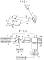
- FIG. 1 schematically shows an embodiment of the light beam scanning apparatus in accordance with the present invention.
- the light beam scanning apparatus comprises a laser beam source 1 constituted by a laser beam oscillator for generating a laser beam 8, and a galvanometer 2 for sweeping the laser beam 8.
- a mirror 10 is secured to a rotation shaft 9 of the galvanometer 2 and is maintained at a mechanically neutral position when the galvanometer 2 is not driven.
- the mirror 10 is rotated back and forth about the neutral position in accordance with the drive current flowing in the galvanometer 2 so that the laser beam is swept from 11A to 11B.
- the laser beam is swept to the 11A side when a negative voltage is applied to the galvanometer 2, and is swept to the 11B side when a positive voltage is applied thereto.
- the laser beam is maintained approximately at the neutral position.
- a start point 6 or an end point 7 of scanning by the laser beam 11A through the laser beam 11B is adjusted by changing the level of the negative or positive voltage applied to the galvanometer 2.
- the scanning speed is adjusted by changing the gradient of the linear change in voltage.
- Scanning of a recording medium 3 by the laser beam 11A through the laser beam 11B is adjusted so that sections outside of the recording medium 3 are also scanned to some extent.
- the recording medium 3 is, for example, a sheet-shaped recording medium for images which may include characters, and is fed by a feed mechanism (not shown) in the direction as indicated by the arrow B. Therefore, the recording medium 3 is scanned to form a scanning line 12 in the main scanning direction indicated by the arrow A by the rotation of the mirror 10 operated by the galvanometer 2, and is simultaneously fed in the sub-scanning direction as indicated by the arrow B. In this manner, a recording surface 13 of the recording medium 3 is scanned by the laser beam 11A through the laser beam llB.
- Photodetectors 4 and 5 for detecting the laser beam are positioned adjacent both edge portions of the recording medium 3 on the scanning line 12.
- the photodetectors 4 and 5 are constituted by photo transistors for receiving the laser beam by light receiving faces and generating positive logic pulses of TTL level.
- the light beam scanning apparatus of Figure 1 When the light beam scanning apparatus of Figure 1 is applied to image read-out, read-out of an image recorded on the recording medium 3 is conducted by detecting the laser beam 11A through the laser beam 11B scanned as described above and reflected by the recording surface 13 or transmitted therethrough.
- the recording medium 3 is an image recording medium comprising a stimulable phosphor carrying a radiation image stored therein, the stimulable phosphor is excited to emit light when exposed to the laser beam 11A through the laser beam llB, and the radiation image is read out by detecting the emitted light.
- a photosensitive material is used as the recording medium 3, and an image is recorded on the photosensitive material by modulating the laser beam 8 emitted by the laser beam source 1 in accordance with an image signal by use of a modulating means (not shown) such as an acousto-optic modulator (AOM).
- a modulating means such as an acousto-optic modulator (AOM).
- Figure 2 shows an example of the circuit configuration for controlling the scanning in the main scanning direction in the apparatus of Figure 1.
- FIG 2 similar elements are numbered with the same reference numerals with respect to Figure 1.
- a pulse P4 generated by the photodetector 4 is sent to the set terminal S of an R-S type flip-flop 15, and a pulse P5 generated by the photodetector 5 is sent to the reset terminal R of the flip-flop 15.
- the flip-flop 15 outputs a high level square wave pulse Pa representing the scanning period between the photodetectors 4 and 5 from the output terminal Q.
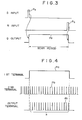
- Figure 3 shows the timing chart of the inputs and the output of the flip-flop 15.
- the square wave pulse Pa is sent to the first terminal of an AND gate 16 constituted by a 74LS08 or the like, and a pulse signal Pb genarated by an oscillator 17 for generating pulses of a predetermined period is sent to the second terminal of the gate 16. From an output terminal of the gate 16 are generated pulses Pc in a number corresponding to the number of pulses Pb input.to the second terminal of the gate 16 within the time corresponding to the aforesaid scanning period.
- Figure 4 shows the timing chart of the inputs and the output of the gate 16.
- the pulses Pc generated by the gate 16 are sent to a counter 18 which is constituted by a decimal counter (74LS196) or the like and which counts the pulses Pc.
- the count n of the pulses Pc is sent to a comparison circuit 19.
- a standard set value n0 representing the number of pulses which should be generated within the time corresponding to the scanning period is specified by external digital switches 20a and 20b, and is sent to the comparison circuit 19.
- the comparison circuit 19 compares the count n and the standard set value n0 with each other, and generates a voltage ⁇ v proportional to the difference n0-n.
- the voltage ⁇ v is superposed on a standard voltage V which has previously been output, and the voltage V+ ⁇ v is applied to a ramp generator 21.
- the ramp generator 21 generates a saw tooth wave output and sends it to the galvanometer 2.
- the mirror 10 secured to the galvanometer 2 is rotated by the saw tooth wave output, and the laser beam 8 is swept from 11A to 11B, thereby forming the scanning line 12.
- the laser beam 11A through the laser beam 11B also scan the photodetectors 4 and 5, causing the photodetectors 4 and 5 to generate the aforesaid pulses P4 and P5.
- the galvanometer 2 is controlled so that the pulse count n between the photodetectors 4 and 5 becomes equal to n0, and the scanning speed of the laser beam is controlled thereby so that it becomes equal to a predetermined value.
- Figure 5 shows another embodiment of the light beam scanning apparatus in accordance with the present invention.
- similar elements are numbered with the same reference numerals with respect to Figure 1.
- a single photodetector 4 for detecting the laser beam is positioned adjacent one edge portion of the recording medium 3 on the scanning line 12.
- Figure 6 shows an example of the circuit configuration for controlling the scanning in the main scanning direction in the apparatus of Figure 5.
- a pulse P5' generated by a means 5 1 for example, a synchronizing signal detector
- the pulse P4 generated by the photodetector 4 is sent to the reset terminal R of the flip-flop 15.
- From the output terminal Q of the flip-flop 15 is output the high level square wave pulse Pa representing the scanning period between the start point detector 5' and the photodetector 4.
- Figure 7 shows the timing chart of the inputs and the output of the flip-flop 15.
- the square wave pulse Pa and the pulse signal Pb are sent to the input terminals of the AND gate 16, and pulses Pc are output from the output terminal of the gate 16 at the same timing as the timing shown in Figure 4.
- the pulses Pc generated by the gate 16 are sent to the counter 18 which counts the pulses Pc.
- the count n of the pulses Pc is sent to a comparison circuit 19' which compares the count n and the standard set value n0 with each other, and generates the voltage Av proportional to the difference n0-n.
- the voltage Av is superposed on a standard voltage V which has previously been output, and the voltage V+Av is applied to the ramp generator 21.
- the ramp generator 21 generates a sawtooth wave output and sends it to the galvanometer 2.
- the mirror 10 secured to the galvanometer 2 is rotated by the sawtooth wave output, and the laser beam 8 is swept from llA to 11B, thereby forming the scanning line 12.
- the laser beam 11A through the laser beam 11B also scan the photodetector 4, and the aforesaid pulse P4 is generated by the photodetector 4.
- the detection pulse P5' representing the start point 6 is generated at the same time by the start point detector 5'.
- the galvanometer 2 is controlled so that the pulse count n becomes equal to n0, and the initial position of the laser beam is controlled thereby so that it is always the same.
Landscapes
- Engineering & Computer Science (AREA)
- Multimedia (AREA)
- Signal Processing (AREA)
- Facsimile Scanning Arrangements (AREA)
- Mechanical Optical Scanning Systems (AREA)
Applications Claiming Priority (4)
| Application Number | Priority Date | Filing Date | Title |
|---|---|---|---|
| JP58251917A JPS60142321A (ja) | 1983-12-28 | 1983-12-28 | 光ビ−ム走査装置 |
| JP251917/83 | 1983-12-28 | ||
| JP251916/83 | 1983-12-28 | ||
| JP58251916A JPS60142320A (ja) | 1983-12-28 | 1983-12-28 | 光ビ−ム走査装置 |
Publications (3)
| Publication Number | Publication Date |
|---|---|
| EP0147835A2 true EP0147835A2 (de) | 1985-07-10 |
| EP0147835A3 EP0147835A3 (en) | 1987-10-07 |
| EP0147835B1 EP0147835B1 (de) | 1991-02-27 |
Family
ID=26540428
Family Applications (1)
| Application Number | Title | Priority Date | Filing Date |
|---|---|---|---|
| EP84116143A Expired - Lifetime EP0147835B1 (de) | 1983-12-28 | 1984-12-21 | Lichtstrahlabtastvorrichtung |
Country Status (3)
| Country | Link |
|---|---|
| US (1) | US4700066A (de) |
| EP (1) | EP0147835B1 (de) |
| DE (1) | DE3484191D1 (de) |
Cited By (4)
| Publication number | Priority date | Publication date | Assignee | Title |
|---|---|---|---|---|
| EP0250132A3 (en) * | 1986-06-07 | 1989-08-02 | Konishiroku Photo Industry Co. Ltd. | Image recording apparatus |
| EP0541321A3 (en) * | 1991-11-07 | 1993-08-25 | Nikon Corporation | Video clock signal generator in an optical scan type image input device |
| US5446556A (en) * | 1991-11-07 | 1995-08-29 | Nikon Corporation | Video clock signal generator in an optical scanner in which a mask including a linear scale provides timing for controlling the amplitude of a vibrating mirror |
| EP0691783A3 (de) * | 1994-07-04 | 1996-04-10 | Fuji Xerox Co Ltd | Bildelement-Taktgenerator |
Families Citing this family (12)
| Publication number | Priority date | Publication date | Assignee | Title |
|---|---|---|---|---|
| JPS6359164A (ja) * | 1986-08-28 | 1988-03-15 | Fuji Photo Film Co Ltd | 光ビ−ム走査装置 |
| US4800270A (en) * | 1987-06-23 | 1989-01-24 | Canadian Patents & Development Ltd. | Galvanometric optical scanning system having a pair of closely located synchronization |
| US4800271A (en) * | 1987-06-23 | 1989-01-24 | Canadian Patents & Development Ltd. | Galvanometric optical scanning system having synchronization photodetectors |
| US5210634A (en) * | 1989-05-16 | 1993-05-11 | Asahi Kogaku Kogyo K.K. | Light beam scanner |
| JP3100478B2 (ja) * | 1992-10-27 | 2000-10-16 | 株式会社トプコン | 往復レーザ走査システムを有するレーザ回転照射装置 |
| KR20010110408A (ko) | 1998-11-25 | 2001-12-13 | 추후제출 | 단일 헤드를 갖는 형광 스크린 스캐닝 장치 |
| US7248387B2 (en) * | 2001-07-31 | 2007-07-24 | Umax Data Systems, Inc. | Scanning speed control device and method |
| US8218183B2 (en) | 2001-07-31 | 2012-07-10 | Transpacific Systems, Llc | Scanning speed control device and method |
| US20050012057A1 (en) * | 2003-05-08 | 2005-01-20 | Alara, Inc. | Method and apparatus for radiation image erasure |
| EP1612582B1 (de) * | 2004-06-29 | 2009-09-09 | Agfa-Gevaert HealthCare GmbH | Verfahren zum Auslesen von in einer Speicherphosphorschicht gespeicherter Röntgeninformationen |
| DE502004002961D1 (de) * | 2004-06-29 | 2007-04-05 | Agfa Gevaert Healthcare Gmbh | Vorrichtung und Verfahren zum Auslesen von in einer Speicherphosphorschicht gespeicherten Röntgeninformationen |
| JP2007336789A (ja) * | 2006-06-19 | 2007-12-27 | Sumitomo Heavy Ind Ltd | モータ駆動装置 |
Family Cites Families (4)
| Publication number | Priority date | Publication date | Assignee | Title |
|---|---|---|---|---|
| US3848087A (en) * | 1973-10-29 | 1974-11-12 | Rca Corp | Optical scanner control system |
| JPS5449147A (en) * | 1977-09-27 | 1979-04-18 | Canon Inc | Recorder |
| JPS6053855B2 (ja) * | 1977-10-24 | 1985-11-27 | キヤノン株式会社 | ガルバノ・ミラ−・スキヤナ装置 |
| US4320420A (en) * | 1980-07-03 | 1982-03-16 | Xerox Corporation | Hybrid bit clock servo |
-
1984
- 1984-12-21 EP EP84116143A patent/EP0147835B1/de not_active Expired - Lifetime
- 1984-12-21 DE DE8484116143T patent/DE3484191D1/de not_active Expired - Lifetime
- 1984-12-27 US US06/686,886 patent/US4700066A/en not_active Expired - Lifetime
Cited By (6)
| Publication number | Priority date | Publication date | Assignee | Title |
|---|---|---|---|---|
| EP0250132A3 (en) * | 1986-06-07 | 1989-08-02 | Konishiroku Photo Industry Co. Ltd. | Image recording apparatus |
| EP0541321A3 (en) * | 1991-11-07 | 1993-08-25 | Nikon Corporation | Video clock signal generator in an optical scan type image input device |
| US5446556A (en) * | 1991-11-07 | 1995-08-29 | Nikon Corporation | Video clock signal generator in an optical scanner in which a mask including a linear scale provides timing for controlling the amplitude of a vibrating mirror |
| EP0748098A3 (de) * | 1991-11-07 | 1997-03-12 | Nippon Kogaku Kk | Videotaktgenerator für einen optischen Bildabtaster |
| EP0691783A3 (de) * | 1994-07-04 | 1996-04-10 | Fuji Xerox Co Ltd | Bildelement-Taktgenerator |
| US5671069A (en) * | 1994-07-04 | 1997-09-23 | Fuji Xerox Co., Ltd. | Pixel clock generator |
Also Published As
| Publication number | Publication date |
|---|---|
| US4700066A (en) | 1987-10-13 |
| DE3484191D1 (de) | 1991-04-04 |
| EP0147835B1 (de) | 1991-02-27 |
| EP0147835A3 (en) | 1987-10-07 |
Similar Documents
| Publication | Publication Date | Title |
|---|---|---|
| US4700066A (en) | Light beam scanning apparatus for reading out or recording an image | |
| US4651226A (en) | Image scanning signal generating apparatus with pre-scan for exposure control | |
| US4638156A (en) | Light beam scanning apparatus with adjustable scanning speed and offset | |
| EP0581083B1 (de) | Fehlerreduktionsverfahren in Abtastsystemen | |
| GB2027950A (en) | Light scanning apparatus | |
| US4268867A (en) | Pixel clock for scanner | |
| EP0057586B1 (de) | Rasterabtastvorrichtung und Verfahren | |
| US4734783A (en) | Shading elimination device for image read-out apparatus | |
| JPS6321167B2 (de) | ||
| US4853535A (en) | Light beam scanning device generating a stable synchronizing signal | |
| GB2099655A (en) | Light beam scan type marking- off device | |
| US4831626A (en) | Laser beam recording apparatus | |
| US4076414A (en) | Motion picture printing apparatus | |
| US4689690A (en) | Synchronizing signal generating circuit | |
| US4803367A (en) | Light beam scanning apparatus employing beam modulation in accordance with the start of scan and end of scan signals | |
| JPH03155267A (ja) | 画像読取装置の感度ムラ補正方法 | |
| JPH01240070A (ja) | 画像読取記録装置 | |
| JPH0519686B2 (de) | ||
| JPS60142320A (ja) | 光ビ−ム走査装置 | |
| JP2692086B2 (ja) | 中間調プリンタ | |
| JPS63244968A (ja) | 光ビ−ム記録装置 | |
| JP2001253114A (ja) | 画像露光記録装置における光量調整方法および装置 | |
| JPH03198039A (ja) | 画像読取装置 | |
| JPH09163097A (ja) | 光ビーム走査装置 | |
| JP2895661B2 (ja) | 画像読取記録同期方式 |
Legal Events
| Date | Code | Title | Description |
|---|---|---|---|
| PUAI | Public reference made under article 153(3) epc to a published international application that has entered the european phase |
Free format text: ORIGINAL CODE: 0009012 |
|
| AK | Designated contracting states |
Designated state(s): DE FR NL |
|
| PUAL | Search report despatched |
Free format text: ORIGINAL CODE: 0009013 |
|
| AK | Designated contracting states |
Kind code of ref document: A3 Designated state(s): DE FR NL |
|
| 17P | Request for examination filed |
Effective date: 19871123 |
|
| 17Q | First examination report despatched |
Effective date: 19890811 |
|
| GRAA | (expected) grant |
Free format text: ORIGINAL CODE: 0009210 |
|
| AK | Designated contracting states |
Kind code of ref document: B1 Designated state(s): DE FR NL |
|
| REF | Corresponds to: |
Ref document number: 3484191 Country of ref document: DE Date of ref document: 19910404 |
|
| ET | Fr: translation filed | ||
| PLBE | No opposition filed within time limit |
Free format text: ORIGINAL CODE: 0009261 |
|
| STAA | Information on the status of an ep patent application or granted ep patent |
Free format text: STATUS: NO OPPOSITION FILED WITHIN TIME LIMIT |
|
| 26N | No opposition filed | ||
| PGFP | Annual fee paid to national office [announced via postgrant information from national office to epo] |
Ref country code: NL Payment date: 20031203 Year of fee payment: 20 |
|
| PGFP | Annual fee paid to national office [announced via postgrant information from national office to epo] |
Ref country code: FR Payment date: 20031218 Year of fee payment: 20 |
|
| PGFP | Annual fee paid to national office [announced via postgrant information from national office to epo] |
Ref country code: DE Payment date: 20040202 Year of fee payment: 20 |
|
| PG25 | Lapsed in a contracting state [announced via postgrant information from national office to epo] |
Ref country code: NL Free format text: LAPSE BECAUSE OF EXPIRATION OF PROTECTION Effective date: 20041221 |
|
| NLV7 | Nl: ceased due to reaching the maximum lifetime of a patent |
Effective date: 20041221 |