EP0148285A1 - Procédé et appareil pour mesurer les profils superficiels - Google Patents
Procédé et appareil pour mesurer les profils superficiels Download PDFInfo
- Publication number
- EP0148285A1 EP0148285A1 EP83113118A EP83113118A EP0148285A1 EP 0148285 A1 EP0148285 A1 EP 0148285A1 EP 83113118 A EP83113118 A EP 83113118A EP 83113118 A EP83113118 A EP 83113118A EP 0148285 A1 EP0148285 A1 EP 0148285A1
- Authority
- EP
- European Patent Office
- Prior art keywords
- height
- measured
- scanning track
- profile
- measuring
- Prior art date
- Legal status (The legal status is an assumption and is not a legal conclusion. Google has not performed a legal analysis and makes no representation as to the accuracy of the status listed.)
- Granted
Links
- 238000000034 method Methods 0.000 title claims abstract description 38
- 239000000523 sample Substances 0.000 claims description 18
- 230000001939 inductive effect Effects 0.000 claims description 2
- 230000010287 polarization Effects 0.000 claims description 2
- 238000005259 measurement Methods 0.000 description 35
- 230000003287 optical effect Effects 0.000 description 9
- 238000006073 displacement reaction Methods 0.000 description 8
- 238000011156 evaluation Methods 0.000 description 8
- 238000012360 testing method Methods 0.000 description 3
- 238000004519 manufacturing process Methods 0.000 description 2
- 241001422033 Thestylus Species 0.000 description 1
- 239000000654 additive Substances 0.000 description 1
- 230000000996 additive effect Effects 0.000 description 1
- 230000001427 coherent effect Effects 0.000 description 1
- 230000001419 dependent effect Effects 0.000 description 1
- 230000007613 environmental effect Effects 0.000 description 1
- 238000005305 interferometry Methods 0.000 description 1
- 238000012544 monitoring process Methods 0.000 description 1
- 230000000737 periodic effect Effects 0.000 description 1
- 238000012545 processing Methods 0.000 description 1
- 238000005070 sampling Methods 0.000 description 1
- 239000004065 semiconductor Substances 0.000 description 1
- 230000036962 time dependent Effects 0.000 description 1
- 230000009466 transformation Effects 0.000 description 1
Images

Classifications
-
- G—PHYSICS
- G01—MEASURING; TESTING
- G01B—MEASURING LENGTH, THICKNESS OR SIMILAR LINEAR DIMENSIONS; MEASURING ANGLES; MEASURING AREAS; MEASURING IRREGULARITIES OF SURFACES OR CONTOURS
- G01B11/00—Measuring arrangements characterised by the use of optical techniques
- G01B11/30—Measuring arrangements characterised by the use of optical techniques for measuring roughness or irregularity of surfaces
- G01B11/303—Measuring arrangements characterised by the use of optical techniques for measuring roughness or irregularity of surfaces using photoelectric detection means
-
- G—PHYSICS
- G01—MEASURING; TESTING
- G01B—MEASURING LENGTH, THICKNESS OR SIMILAR LINEAR DIMENSIONS; MEASURING ANGLES; MEASURING AREAS; MEASURING IRREGULARITIES OF SURFACES OR CONTOURS
- G01B7/00—Measuring arrangements characterised by the use of electric or magnetic techniques
- G01B7/34—Measuring arrangements characterised by the use of electric or magnetic techniques for measuring roughness or irregularity of surfaces
- G01B7/345—Measuring arrangements characterised by the use of electric or magnetic techniques for measuring roughness or irregularity of surfaces for measuring evenness
Definitions
- the invention relates to a method for measuring surface profiles according to the preamble of claim 1 and devices for performing the method.
- Mechanical probe cut methods or optical interference methods are used today for such high-precision measurements.
- the tactile cut method the surface to be tested is traversed with a fine measuring tip, the deflection of which is converted into an electrical measured value perpendicular to the measured surface by a measuring transducer.
- the achievable height resolution of this method is better than 10 nanometers, but extremely high pressures occur when the probe tip comes into contact with the surface, which can easily lead to scratches or other damage.
- Optical interference methods do not have this disadvantage, since there is a contactless scanning of the surface.
- Another advantage of this method is the possibility of generating profiles not only along selected scanning lines, but also large-area interference images with which the profile of the entire surface can be recorded. From evaluation of the resulting optical interference images is very complex and therefore prone to errors; an automatic evaluation requires a powerful computer.
- optical interferometer arrangements can also be used, in which a (point-shaped) measuring beam reflected from the surface to be examined is superimposed with a reference beam which was reflected, for example, on a stationary mirror.
- a (point-shaped) measuring beam reflected from the surface to be examined is superimposed with a reference beam which was reflected, for example, on a stationary mirror.
- the measurement resolution can be increased to a few nanometers.
- the present invention therefore has the task of specifying a method of the type mentioned at the outset which permits profile measurements which are influenced as little as possible by guide errors in the relative displacement between the measuring probe and the surface. Facilities are to be implemented to carry out the process that require little effort and enable quick measurements.
- the surface to be examined is simultaneously subjected to two measuring probes which are arranged one behind the other in the scanning direction and are at a certain mutual distance.
- the local height difference measured between the two scanning points is then integrated along the scanning track in order to obtain the profile corresponding to this track.
- An optical two-beam interferometer is preferably used to measure the local height difference, in which the phase difference between the two beams is determined with great accuracy using an electro-optical compensation method.
- the proposed method is also suitable for other scanning devices, for example the probe cut method, if two such tips are arranged one behind the other instead of a single measuring tip; inductive or capacitive probes are also possible.
- surface profiles can be recorded with a measuring accuracy of a few nanometers, although the devices used for the relative displacement between the measuring probes and the surface, for example cross tables, have guide errors that are orders of magnitude higher (for example, pitch, angular displacement).
- the profile measurement can be performed quickly, provides unique, independent of the operator results and can handle g ungsline automatically in a Ferti. Play environmental influences such as temperature and humidity despite the high measurement resolution, it doesn't matter. If the twisting of a surface is to be determined, the connecting line of the two sensors is perpendicular to the scanning track.
- the height difference between the points of impact of sensors 3 and 4 is measured. This can be done, for example, by using mechanical probe tips as sensors 3, 4; in this case the local height difference is equal to the difference between the two mechanical deflections read.
- the two sensors 3 and 4 consist of two coherent light bundles which are focused on the surface 2 and have a phase difference after reflection, which is determined by electro-optical compensation.
- phase-sensitive two-beam interferometer differential interferometer
- 2 comprises a laser 20, the output beam of which passes through an X / 2 plate 21, a polarizer 22 and an electro-optical modulator 23, in which the two partial beams polarized perpendicular to each other are imprinted with a periodic relative phase difference.
- the two bundles of different polarization directions are then split up in the birefringent element 25 and directed by an optical system 26 onto the surface of the sample body 27 to be examined, which is shown with a step in FIG. 2.
- the two reflected beams 3 and 4 are reunited in the birefringent element 25 and deflected at the deflecting mirror 24 to a polarizer 28 and a photodetector 29.
- the photodetector supplies a time-dependent signal, from which the instantaneous phase difference of the two beams 3 and 4, and thus their height difference h i , can be determined with great accuracy (for example by determining the zero crossings) in the evaluation unit 30.
- the height resolution of this arrangement is approximately 1 nanometer.
- the evaluation unit 30 delivers the respectively determined local height difference hi to a computer, which also receives a position signal for the current position of the surface 27.
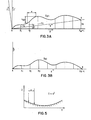
- the measuring method itself will now be explained with reference to FIG. 3. It is assumed that the sample body 1 is attached to an XY table and is continuously moved along a straight line under the stationary double sensor.
- the profile to be measured is described in accordance with FIG. 3A in a z'x 'coordinate system which is moved along with the table.
- the Koor The origin of the data coincides with the left edge point A of the profile to be measured.
- the z l axis runs parallel to the axes of the double sensor (for example the center rays of the light beams 3 and 4 in FIG. 1).
- the object on the XY table will be inclined so that the right edge point B of the profile will not lie on the x'-axis, but above or below it.
- the values h '(x k ') are the height differences which are measured when the right sensor touches the profile point z '(x' k ), while the left sensor the profile point z '(x' k -d ) touches.
- the measured values selected in this way are therefore:
- FIG. 3B shows the function z (x) as the result of this coordinate transformation, which corresponds to the sought profile determined from the measured height differences h (x '). Since measured values were only evaluated at points x i , the intermediate values must be determined by interpolation in order to obtain the profile height at each point on the x axis.
- the respective x coordinate i.e. the displacement of the double sensor with respect to the surface to be examined can be known.
- This value can either be determined by measuring the displacement of the sample body (for example by an interferometer connected to the X-Y table) or, in the case of a linear, uniform movement, over the time of the respective measurement.
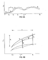
- FIGS. 4A and 4B occur in order to make one of the essential advantages of the method proposed here clear, namely its relative insensitivity to guiding errors, even of a rough nature.
- FIG. 4A schematically shows the profile height fluctuations of the measurement object according to FIG. 3A when guide errors occur.
- the profile elements S 1 , S 2 ... S N which are individually touched one after the other, experience incorrect height and angle fluctuations during the table movement.
- the profile curve z (x) shown in FIG. 3B can be represented in the following manner from the measured height differences h., which are taken from the measurement curve according to FIG. 3A (or according to FIG. 4A): if it is assumed that the gradient angles occurring in the measurement curves are small (so that tanß ⁇ ⁇ ).
- Each profile height value z (x k ) is thus additively composed of N summands, each of which is multiplied by a factor (1 - K / N) or (- K / N).
- the error of the individual measured value h i is, as usual, expressed by the standard deviation ⁇ .
- the standard deviation results from the sum of the variances of the individual measurements, i.e.:
- the measurement error of the method proposed here is therefore location-dependent and has a maximum ü k in the middle of the scanning track:
- the maximum measurement error ü k is determined by the error u 0 of the individual measurement h i . This in turn essentially depends on two factors, the instrument error ⁇ i of the device with which the local height difference is determined and the straight line error (by the Angular deviation) of the specimen, which is given by a standard deviation ⁇ ⁇ . The relationship applies to the latter error: where a is the tilt angle shown in FIG. 4B and d, as always, is the distance between the double sensors.
- the total error of the individual measurement (in the above, the height shift ⁇ z is not included) can therefore be described by a standard deviation u 0 , which is created by adding the variants of instrument error ⁇ i and angular error ⁇ ⁇ of the individual measurement h k :
- the optimal sensor distance d can be determined from this relationship, at which the measurement error û k becomes a minimum; for this the condition
- the improvement in the measurement resolution by the double sensor method proposed here can be illustrated in the following example, for which it is assumed that one and the same profile is recorded once using the conventional stylus method and once using the double sensor principle.
- equation (13) yields a maximum error of
- the double sensor method offers 40 times higher profile measuring accuracy.
- the measured height differences h i can be fed to a computer 31 (see FIG. 2) together with the associated table displacements Ax. If production monitoring is to be carried out, the output signal of this computer can in turn be used as a manipulated variable for a device which is provided for processing the measured surfaces. Due to the high measuring speed achieved in the automatic evaluation (in the range of seconds for profiles over a length of 10 cm), multiple scans in different coordinate directions are also possible in order to generate flat profile sections.
- the method proposed here can also be used for scanning tracks other than flat.
- 5 shows an example for the profile determination of a parabolic surface with a double sensor arrangement.
- the double sensor arrangement can also be used to determine the twisting of a surface; for this purpose, the second sensor is arranged at a distance d perpendicular to the scanning track.
Landscapes
- Physics & Mathematics (AREA)
- General Physics & Mathematics (AREA)
- Length Measuring Devices By Optical Means (AREA)
- Length Measuring Devices With Unspecified Measuring Means (AREA)
Priority Applications (3)
| Application Number | Priority Date | Filing Date | Title |
|---|---|---|---|
| DE8383113118T DE3376502D1 (en) | 1983-12-27 | 1983-12-27 | Method and apparatus for measuring surface profiles |
| EP19830113118 EP0148285B1 (fr) | 1983-12-27 | 1983-12-27 | Procédé et appareil pour mesurer les profils superficiels |
| JP24353784A JPS60186707A (ja) | 1983-12-27 | 1984-11-20 | 表面プロフイ−ルの測定方法 |
Applications Claiming Priority (1)
| Application Number | Priority Date | Filing Date | Title |
|---|---|---|---|
| EP19830113118 EP0148285B1 (fr) | 1983-12-27 | 1983-12-27 | Procédé et appareil pour mesurer les profils superficiels |
Publications (2)
| Publication Number | Publication Date |
|---|---|
| EP0148285A1 true EP0148285A1 (fr) | 1985-07-17 |
| EP0148285B1 EP0148285B1 (fr) | 1988-05-04 |
Family
ID=8190908
Family Applications (1)
| Application Number | Title | Priority Date | Filing Date |
|---|---|---|---|
| EP19830113118 Expired EP0148285B1 (fr) | 1983-12-27 | 1983-12-27 | Procédé et appareil pour mesurer les profils superficiels |
Country Status (3)
| Country | Link |
|---|---|
| EP (1) | EP0148285B1 (fr) |
| JP (1) | JPS60186707A (fr) |
| DE (1) | DE3376502D1 (fr) |
Cited By (2)
| Publication number | Priority date | Publication date | Assignee | Title |
|---|---|---|---|---|
| WO1996019802A1 (fr) * | 1994-12-19 | 1996-06-27 | Seagate Technology, Inc. | Calcul de la pente au niveau du diametre exterieur dans un procede de fabrication de disques magnetiques |
| CN111638230A (zh) * | 2019-03-01 | 2020-09-08 | Oppo(重庆)智能科技有限公司 | 终端镜片检测方法、装置、电子设备及存储介质 |
Families Citing this family (4)
| Publication number | Priority date | Publication date | Assignee | Title |
|---|---|---|---|---|
| DE3574280D1 (en) * | 1985-12-23 | 1989-12-21 | Ibm Deutschland | Method and arrangement for optically determining surface profiles |
| JPH0769143B2 (ja) * | 1988-01-22 | 1995-07-26 | 株式会社ミツトヨ | 光ヘテロダインエッジセンサー及びスケール精度測定装置 |
| IT1236602B (it) * | 1989-12-22 | 1993-03-18 | Sgs Thomson Microelectronics | Caratterizzazione quantitativa della distorsione geometrica subita da un profilo superficiale di un "wafer". |
| US9740190B2 (en) * | 2014-10-09 | 2017-08-22 | Mitutoyo Corporation | Method for programming a three-dimensional workpiece scan path for a metrology system |
Citations (6)
| Publication number | Priority date | Publication date | Assignee | Title |
|---|---|---|---|---|
| DE1068025B (fr) * | 1959-10-29 | |||
| FR2280054A1 (fr) * | 1974-07-22 | 1976-02-20 | Nippon Kokan Kk | Procede et appareil pour mesurer la planeite de materiaux |
| EP0011708A1 (fr) * | 1978-11-30 | 1980-06-11 | International Business Machines Corporation | Méthode et dispositif pour mesurer la planéité, la rugosité ou le rayon de courbure d'une surface à mesurer |
| EP0021148A1 (fr) * | 1979-06-22 | 1981-01-07 | International Business Machines Corporation | Procédé et dispositif de mesure interférométrique |
| CH630016A5 (en) * | 1979-03-06 | 1982-05-28 | Speno International | Device for measuring the undulating-type deformations of the rolling surface of the rails of a railway |
| US4353650A (en) * | 1980-06-16 | 1982-10-12 | The United States Of America As Represented By The United States Department Of Energy | Laser heterodyne surface profiler |
Family Cites Families (2)
| Publication number | Priority date | Publication date | Assignee | Title |
|---|---|---|---|---|
| JPS5510557A (en) * | 1978-07-10 | 1980-01-25 | Toshiba Corp | Mobile track measuring device |
| JPS6055004B2 (ja) * | 1979-07-27 | 1985-12-03 | 日本国有鉄道 | 軌道狂い演算装置 |
-
1983
- 1983-12-27 DE DE8383113118T patent/DE3376502D1/de not_active Expired
- 1983-12-27 EP EP19830113118 patent/EP0148285B1/fr not_active Expired
-
1984
- 1984-11-20 JP JP24353784A patent/JPS60186707A/ja active Pending
Patent Citations (6)
| Publication number | Priority date | Publication date | Assignee | Title |
|---|---|---|---|---|
| DE1068025B (fr) * | 1959-10-29 | |||
| FR2280054A1 (fr) * | 1974-07-22 | 1976-02-20 | Nippon Kokan Kk | Procede et appareil pour mesurer la planeite de materiaux |
| EP0011708A1 (fr) * | 1978-11-30 | 1980-06-11 | International Business Machines Corporation | Méthode et dispositif pour mesurer la planéité, la rugosité ou le rayon de courbure d'une surface à mesurer |
| CH630016A5 (en) * | 1979-03-06 | 1982-05-28 | Speno International | Device for measuring the undulating-type deformations of the rolling surface of the rails of a railway |
| EP0021148A1 (fr) * | 1979-06-22 | 1981-01-07 | International Business Machines Corporation | Procédé et dispositif de mesure interférométrique |
| US4353650A (en) * | 1980-06-16 | 1982-10-12 | The United States Of America As Represented By The United States Department Of Energy | Laser heterodyne surface profiler |
Cited By (2)
| Publication number | Priority date | Publication date | Assignee | Title |
|---|---|---|---|---|
| WO1996019802A1 (fr) * | 1994-12-19 | 1996-06-27 | Seagate Technology, Inc. | Calcul de la pente au niveau du diametre exterieur dans un procede de fabrication de disques magnetiques |
| CN111638230A (zh) * | 2019-03-01 | 2020-09-08 | Oppo(重庆)智能科技有限公司 | 终端镜片检测方法、装置、电子设备及存储介质 |
Also Published As
| Publication number | Publication date |
|---|---|
| EP0148285B1 (fr) | 1988-05-04 |
| DE3376502D1 (en) | 1988-06-09 |
| JPS60186707A (ja) | 1985-09-24 |
Similar Documents
| Publication | Publication Date | Title |
|---|---|---|
| DE69505749T2 (de) | Dickenmessverfahren für transparentes material | |
| DE69024833T2 (de) | Spiegelinterferometer für Linear- und Winkelmessungen | |
| DE3428593A1 (de) | Optisches oberflaechenmessgeraet | |
| DE10214490B4 (de) | Verfahren zur Korrektur von Führungsfehlern bei einem Koordinatenmeßgerät | |
| EP0082441A2 (fr) | Procédé et dispositif pour évaluer et corriger les fautes de guidage | |
| DE102017122689A1 (de) | Verfahren und Vorrichtung zur berührungslosen Messung eines Abstands zu einer Oberfläche oder eines Abstands zwischen zwei Oberflächen | |
| DE69900557T2 (de) | Vorrichtung zur Kontrolle und/oder Bearbeitung eines Musters | |
| DE10050749A1 (de) | Laserinterferenzeinrichtung | |
| DE68908828T2 (de) | Verfahren zur Einkerbung und Inspektion einer V-Kerbe. | |
| EP3435032A1 (fr) | Capteur optique de rugosité pour une machine de mesure de coordonnées | |
| EP0148285B1 (fr) | Procédé et appareil pour mesurer les profils superficiels | |
| DE4421302C1 (de) | Verfahren zur Eliminierung des Rollwinkels einer Meßachse einer Koordinatenmeßmaschine sowie Vorrichtung zur Durchführung des Verfahrens | |
| DE2164347C3 (de) | Meß vorrichtung zum Messen der Gewindesteigung einer Gewindespindel | |
| DE10043635A1 (de) | Vorrichtung zur Positionsbestimmung und Ermittlung von Führungsfehlern | |
| DE3636744C1 (de) | Lichtelektrische Laengen- oder Winkelmesseinrichtung | |
| DD241643A1 (de) | Messverfahren und vorrichtung zur beruehrungslosen durchmesserbestimmung duenner draehte | |
| EP0499074B1 (fr) | Interféromètre à polarisation comportant un filtre à bande étroite | |
| EP3869161B1 (fr) | Dispositif optique de mesure de position | |
| DE10337894A1 (de) | Optisches Messsystem zum Erfassen von Geometriedaten von Oberflächen | |
| DE3309951C2 (de) | Optoelektronisches Dehnungsmeßgerät mit berührungsloser Abtastung eines oder mehrerer am Meßobjekt angebrachter Meßgitter | |
| DE19842190C1 (de) | Verfahren zur Bestimmung der Topographie von gekrümmten Oberflächen | |
| DE4100773C2 (de) | Interferometrische Längenmeßeinrichtung | |
| DE3503116A1 (de) | Messinstrument | |
| DE2308643A1 (de) | Verfahren und vorrichtung zum messen und interpolieren mit einem praezisionsmassstab | |
| EP2032948A1 (fr) | Dispositif de détermination de la position d'un objet déplaçable le long d'au moins une direction de déplacement |
Legal Events
| Date | Code | Title | Description |
|---|---|---|---|
| PUAI | Public reference made under article 153(3) epc to a published international application that has entered the european phase |
Free format text: ORIGINAL CODE: 0009012 |
|
| 17P | Request for examination filed |
Effective date: 19841016 |
|
| AK | Designated contracting states |
Designated state(s): DE FR GB |
|
| 17Q | First examination report despatched |
Effective date: 19860828 |
|
| GRAA | (expected) grant |
Free format text: ORIGINAL CODE: 0009210 |
|
| AK | Designated contracting states |
Kind code of ref document: B1 Designated state(s): DE FR GB |
|
| GBT | Gb: translation of ep patent filed (gb section 77(6)(a)/1977) | ||
| REF | Corresponds to: |
Ref document number: 3376502 Country of ref document: DE Date of ref document: 19880609 |
|
| ET | Fr: translation filed | ||
| PLBE | No opposition filed within time limit |
Free format text: ORIGINAL CODE: 0009261 |
|
| STAA | Information on the status of an ep patent application or granted ep patent |
Free format text: STATUS: NO OPPOSITION FILED WITHIN TIME LIMIT |
|
| 26N | No opposition filed | ||
| PGFP | Annual fee paid to national office [announced via postgrant information from national office to epo] |
Ref country code: GB Payment date: 19911111 Year of fee payment: 9 |
|
| PGFP | Annual fee paid to national office [announced via postgrant information from national office to epo] |
Ref country code: FR Payment date: 19911127 Year of fee payment: 9 |
|
| PGFP | Annual fee paid to national office [announced via postgrant information from national office to epo] |
Ref country code: DE Payment date: 19911221 Year of fee payment: 9 |
|
| PG25 | Lapsed in a contracting state [announced via postgrant information from national office to epo] |
Ref country code: GB Effective date: 19921227 |
|
| GBPC | Gb: european patent ceased through non-payment of renewal fee |
Effective date: 19921227 |
|
| PG25 | Lapsed in a contracting state [announced via postgrant information from national office to epo] |
Ref country code: FR Effective date: 19930831 |
|
| PG25 | Lapsed in a contracting state [announced via postgrant information from national office to epo] |
Ref country code: DE Effective date: 19930901 |
|
| REG | Reference to a national code |
Ref country code: FR Ref legal event code: ST |