EP0148313A1 - Culasse pour canon - Google Patents
Culasse pour canon Download PDFInfo
- Publication number
- EP0148313A1 EP0148313A1 EP84105874A EP84105874A EP0148313A1 EP 0148313 A1 EP0148313 A1 EP 0148313A1 EP 84105874 A EP84105874 A EP 84105874A EP 84105874 A EP84105874 A EP 84105874A EP 0148313 A1 EP0148313 A1 EP 0148313A1
- Authority
- EP
- European Patent Office
- Prior art keywords
- ring
- low
- pressure side
- closure
- eyelid
- Prior art date
- Legal status (The legal status is an assumption and is not a legal conclusion. Google has not performed a legal analysis and makes no representation as to the accuracy of the status listed.)
- Granted
Links
- 210000000744 eyelid Anatomy 0.000 claims abstract description 33
- 230000006835 compression Effects 0.000 claims description 5
- 238000007906 compression Methods 0.000 claims description 5
- 210000003128 head Anatomy 0.000 abstract description 8
- 238000011161 development Methods 0.000 description 5
- 230000018109 developmental process Effects 0.000 description 5
- 239000007789 gas Substances 0.000 description 4
- 238000011179 visual inspection Methods 0.000 description 3
- 238000010304 firing Methods 0.000 description 2
- 238000012544 monitoring process Methods 0.000 description 2
- 230000002950 deficient Effects 0.000 description 1
- 230000000694 effects Effects 0.000 description 1
- 229920001971 elastomer Polymers 0.000 description 1
- 239000000806 elastomer Substances 0.000 description 1
- 239000012528 membrane Substances 0.000 description 1
- 230000002028 premature Effects 0.000 description 1
- 239000012858 resilient material Substances 0.000 description 1
- 238000007789 sealing Methods 0.000 description 1
- 230000001960 triggered effect Effects 0.000 description 1
Images

Classifications
-
- F—MECHANICAL ENGINEERING; LIGHTING; HEATING; WEAPONS; BLASTING
- F41—WEAPONS
- F41A—FUNCTIONAL FEATURES OR DETAILS COMMON TO BOTH SMALLARMS AND ORDNANCE, e.g. CANNONS; MOUNTINGS FOR SMALLARMS OR ORDNANCE
- F41A3/00—Breech mechanisms, e.g. locks
- F41A3/64—Mounting of breech-blocks; Accessories for breech-blocks or breech-block mountings
- F41A3/74—Obturating or packing devices for gas leak prevention in breech mechanisms
Definitions
- the invention relates to a breech for a gun according to the preamble of claim 1.
- Such a closure is known for example from DE-OS 15 78 046.
- the exchangeable eyelid ring is a wearing part that - depending on the load on the gun - is worn out and must be replaced in good time to prevent serious consequential damage and possibly also endanger the gun crew.
- the invention has for its object to provide a device for continuous monitoring of the proper condition of the eyelid ring.
- the invention enables continuous monitoring of the state of the eyelid ring in a simple manner in all operating modes of the gun, in particular also when shooting with high cadence. Inadmissible wear of the eyelid ring is indicated in good time, so that serious consequential damage and a danger to the operating team are excluded.
- the gun is deactivated as a precaution in order to enable the defective eyelid ring to be replaced.
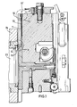
- Fig. 1 shows in a sectional view the breech 11 of the gun, here in particular a wedge, which closes the cargo space 23 of the gun barrel 24.
- a gas-tight seal between the cargo space 23 and the closure 11 is achieved by an annular encircling eyelet ring 14 made of a resilient material, for. B, an elastomer and is designed to be interchangeable.
- This eyelid ring 14 is a wearing part, which is subject to wear due to heavy use of the gun and must therefore be replaced from time to time when its sealing effect wears off. In addition, improper placement of a projectile can damage the eyelid ring 14, which necessitates its premature replacement.
- a continuous objective control of the degree of wear of the eyelid ring 14 is achieved in that means are provided for determining and displaying an impermissibly high gas pressure on the low-pressure side of the eyelid ring 1 4.
- the invention is based on the knowledge that a damaged eyelid ring 14 leads to a measurable pressure increase on the low pressure side of the eyelid ring.
- the means for determining and displaying an impermissibly high gas pressure on the low-pressure side of the eyelet ring preferably consist of a signal pin 10 with an indicator head 10 ', which is slidably mounted in a bore 12 arranged in the closure 11 and which is connected to the low-pressure-side boundary surface via a gas-permeable channel 13 the eyelet ring 14 is connected.
- the signal pin 10, 10 ' is loaded by a compression spring 15 (Fig. 3) such that the indicator head 10' of the signal pin 10 in the rest position, that is, with the eyelid ring 14 intact, is flush with the surface 11 'of the closure 11.
- the spring force of the compression spring 15 and the friction between the signal pin 10 and the inner lateral surface of the bore 12 are matched to one another in such a way that the signal pin 10 remains in its alarm position after being triggered by an increase in pressure on the low-pressure side of the eyelet ring 14. After the damaged eyelid ring 14 has been replaced, the signal pin 10 is pressed back into its ready position by simple finger pressure on the display head 10 ′ and is available for a renewed display of an impermissible pressure increase.
- Fig. 2 shows an enlarged view of section 2 from Fig. 1 and clearly shows how the low-pressure side of the eyelet ring 14 is connected via a gas-permeable channel 13 to the bore 12 which carries the signal pin 10, 10 '.
- the eyelid ring 14 has two circumferential grooves 20, 21 (FIG. 4) on its low-pressure side boundary surface, which are connected to one another by at least one bore 22.
- the mouth of the gas-permeable channel 13, which is distant from the signal pin 10, is aligned with at least one of the circumferential grooves 20, 21 arranged in the eyelet ring 14 in such a way that gases which have reached the low-pressure side of the eyelid ring 14 pass through the circumferential grooves 20, 21 or also through the bore 22 and can spread through the channel 13 towards the bore 12.
- a signal circuit 18 is provided which can be closed via a switch 16 which can be actuated by the display head 10 'of the signal pin 10 as soon as the signal pin 10 is pressed in the alarm position. After closing the signal circuit 18, a signal lamp 17 lights up.
- an alarm transmitter not shown in the drawing, can be activated, which warns the operating team by means of an acoustic signal.
- a control circuit 19 is provided in the signal circuit 18, which when the pressure rises on the low-pressure side of the eyelid ring 14 as a result of its damage, ie. H. that is, after the signal circuits 18 are closed by the switch 16, and the gun functions are prevented.
- the control circuit 19 consists, for example, of relay circuits which are known per se and which switch off the drive sources of the gun.
- the signal pin 10, 10 ' which acts as an alarm indicator and switching element can also be replaced by a membrane switch which responds to pressure differences and which has corresponding contacts for closing the signal circuit. In this case, however, it is no longer possible to manually feel the alarm state in a simple manner.
Landscapes
- Engineering & Computer Science (AREA)
- General Engineering & Computer Science (AREA)
- Measuring Fluid Pressure (AREA)
Applications Claiming Priority (2)
| Application Number | Priority Date | Filing Date | Title |
|---|---|---|---|
| DE19833322437 DE3322437A1 (de) | 1983-06-22 | 1983-06-22 | Verschluss fuer ein geschuetz |
| DE3322437 | 1983-06-22 |
Publications (2)
| Publication Number | Publication Date |
|---|---|
| EP0148313A1 true EP0148313A1 (fr) | 1985-07-17 |
| EP0148313B1 EP0148313B1 (fr) | 1987-01-21 |
Family
ID=6202067
Family Applications (1)
| Application Number | Title | Priority Date | Filing Date |
|---|---|---|---|
| EP84105874A Expired EP0148313B1 (fr) | 1983-06-22 | 1984-05-23 | Culasse pour canon |
Country Status (3)
| Country | Link |
|---|---|
| US (1) | US4566368A (fr) |
| EP (1) | EP0148313B1 (fr) |
| DE (2) | DE3322437A1 (fr) |
Cited By (1)
| Publication number | Priority date | Publication date | Assignee | Title |
|---|---|---|---|---|
| BE1008672A3 (fr) * | 1993-05-20 | 1996-07-02 | British Aerospace | Armes d'infanterie. |
Families Citing this family (3)
| Publication number | Priority date | Publication date | Assignee | Title |
|---|---|---|---|---|
| DE3404676A1 (de) * | 1984-02-10 | 1985-08-14 | Rheinmetall GmbH, 4000 Düsseldorf | Ringliderung an geschuetzen |
| DE3806123A1 (de) * | 1988-02-26 | 1989-09-07 | Rheinmetall Gmbh | Verschlussmechanismus fuer eine rohrwaffe |
| DE10213928A1 (de) * | 2002-03-28 | 2003-10-09 | Rheinmetall W & M Gmbh | Mörserrohr |
Citations (1)
| Publication number | Priority date | Publication date | Assignee | Title |
|---|---|---|---|---|
| DE1578046A1 (de) * | 1966-12-14 | 1970-10-15 | Rheinmetall Gmbh | Keilverschluss fuer Geschuetze mit auswechselbarer Ringliderung |
Family Cites Families (3)
| Publication number | Priority date | Publication date | Assignee | Title |
|---|---|---|---|---|
| US167981A (en) * | 1875-09-21 | Improvement in gas-checks for ordnance | ||
| US2475387A (en) * | 1945-11-02 | 1949-07-05 | Golden Sidney | Ordnance pressure time recorder |
| US3738224A (en) * | 1971-11-23 | 1973-06-12 | Us Army | Obturated firearm breech safety device |
-
1983
- 1983-06-22 DE DE19833322437 patent/DE3322437A1/de not_active Withdrawn
-
1984
- 1984-05-23 EP EP84105874A patent/EP0148313B1/fr not_active Expired
- 1984-05-23 DE DE8484105874T patent/DE3462178D1/de not_active Expired
- 1984-06-22 US US06/623,552 patent/US4566368A/en not_active Expired - Fee Related
Patent Citations (1)
| Publication number | Priority date | Publication date | Assignee | Title |
|---|---|---|---|---|
| DE1578046A1 (de) * | 1966-12-14 | 1970-10-15 | Rheinmetall Gmbh | Keilverschluss fuer Geschuetze mit auswechselbarer Ringliderung |
Cited By (1)
| Publication number | Priority date | Publication date | Assignee | Title |
|---|---|---|---|---|
| BE1008672A3 (fr) * | 1993-05-20 | 1996-07-02 | British Aerospace | Armes d'infanterie. |
Also Published As
| Publication number | Publication date |
|---|---|
| US4566368A (en) | 1986-01-28 |
| DE3462178D1 (en) | 1987-02-26 |
| EP0148313B1 (fr) | 1987-01-21 |
| DE3322437A1 (de) | 1985-01-03 |
Similar Documents
| Publication | Publication Date | Title |
|---|---|---|
| DE60109718T2 (de) | Selbstladende Handfeuerwaffe | |
| DE60222708T2 (de) | Zählvorrichtung | |
| DE68915858T2 (de) | Sicherheitsvorrichtung für den Bolzen einer automatischen oder halbautomatischen Pistole. | |
| EP0148313B1 (fr) | Culasse pour canon | |
| EP0130355A1 (fr) | Amortisseur de culasse pour arme à feu automatique | |
| EP0396946A2 (fr) | Dispositif à loupe | |
| DE3317001A1 (de) | Einrichtung zur ueberwachung ein oder mehrerer schusswaffen, sowie der die schusswaffen betaetigenden schuetzen | |
| DE2241751B2 (de) | Kugelgelenk | |
| EP0341543A1 (fr) | Cartouche à balle pour fusil | |
| WO2022003123A1 (fr) | Pare-flamme | |
| EP1837111A2 (fr) | Installation d'ébarbage thermique dotée d'une ventilation rapide | |
| DE3510462A1 (de) | Druckbegrenzungsventil mit abgedichtetem federraum | |
| EP0156983A1 (fr) | Couloir à munitions d'un canon | |
| DE2624417A1 (de) | Geschuetzrohr | |
| EP3301010B1 (fr) | Flotteur gonflable avec indicateur d'étanchéité | |
| DE705557C (de) | Patrone fuer Geschuetzrohre | |
| EP4560249B1 (fr) | Détente à poids de détente réglable pas à pas pour armes de type ar | |
| DE102021000216B4 (de) | Ladezustandsanzeige fernbedienbarer Waffenstationen | |
| CH691556A5 (de) | Vorrichtung zur Befestigung einer Patronenhülse an einem Geschoss. | |
| DE29821994U1 (de) | Diagnose-Sonde für eine Mehrzellen-Batterie | |
| DE1773464A1 (de) | Druckveraenderungsabtast- und Anzeigegeraet | |
| DE69712935T2 (de) | Vorrichtung zur fernbetätigten Druckentlastung des Füllgases eines Leistungsschalters | |
| AT155191B (de) | Einrichtung zur selbsttätigen Warnung bei Explosionsgefahr. | |
| DE2953643C1 (de) | Elektrische Ausloesevorrichtung fuer Schusswaffen | |
| EP1231686A1 (fr) | Moyens de signalisation pour indication du déclenchement d'un dérivateur de surtensions |
Legal Events
| Date | Code | Title | Description |
|---|---|---|---|
| PUAI | Public reference made under article 153(3) epc to a published international application that has entered the european phase |
Free format text: ORIGINAL CODE: 0009012 |
|
| 17P | Request for examination filed |
Effective date: 19850424 |
|
| AK | Designated contracting states |
Designated state(s): DE FR GB SE |
|
| 17Q | First examination report despatched |
Effective date: 19860409 |
|
| GRAA | (expected) grant |
Free format text: ORIGINAL CODE: 0009210 |
|
| AK | Designated contracting states |
Kind code of ref document: B1 Designated state(s): DE FR GB SE |
|
| REF | Corresponds to: |
Ref document number: 3462178 Country of ref document: DE Date of ref document: 19870226 |
|
| ET | Fr: translation filed | ||
| PLBE | No opposition filed within time limit |
Free format text: ORIGINAL CODE: 0009261 |
|
| STAA | Information on the status of an ep patent application or granted ep patent |
Free format text: STATUS: NO OPPOSITION FILED WITHIN TIME LIMIT |
|
| 26N | No opposition filed | ||
| PGFP | Annual fee paid to national office [announced via postgrant information from national office to epo] |
Ref country code: SE Payment date: 19900417 Year of fee payment: 7 |
|
| PG25 | Lapsed in a contracting state [announced via postgrant information from national office to epo] |
Ref country code: SE Effective date: 19910524 |
|
| PGFP | Annual fee paid to national office [announced via postgrant information from national office to epo] |
Ref country code: FR Payment date: 19930428 Year of fee payment: 10 |
|
| PGFP | Annual fee paid to national office [announced via postgrant information from national office to epo] |
Ref country code: DE Payment date: 19930429 Year of fee payment: 10 |
|
| PGFP | Annual fee paid to national office [announced via postgrant information from national office to epo] |
Ref country code: GB Payment date: 19930517 Year of fee payment: 10 |
|
| PG25 | Lapsed in a contracting state [announced via postgrant information from national office to epo] |
Ref country code: GB Effective date: 19940523 |
|
| GBPC | Gb: european patent ceased through non-payment of renewal fee |
Effective date: 19940523 |
|
| EUG | Se: european patent has lapsed |
Ref document number: 84105874.6 Effective date: 19911209 |
|
| PG25 | Lapsed in a contracting state [announced via postgrant information from national office to epo] |
Ref country code: FR Effective date: 19950131 |
|
| PG25 | Lapsed in a contracting state [announced via postgrant information from national office to epo] |
Ref country code: DE Effective date: 19950201 |
|
| REG | Reference to a national code |
Ref country code: FR Ref legal event code: ST |