EP0148756A2 - System zum Aufwertem thermischer Energie mit niedrigem Niveau unter Ausnutzung der Verdampfung, und Mischung zweier strömender Medien mit gleichem Dampfdruck bei unterschiedlichen Temperaturen - Google Patents
System zum Aufwertem thermischer Energie mit niedrigem Niveau unter Ausnutzung der Verdampfung, und Mischung zweier strömender Medien mit gleichem Dampfdruck bei unterschiedlichen Temperaturen Download PDFInfo
- Publication number
- EP0148756A2 EP0148756A2 EP85101378A EP85101378A EP0148756A2 EP 0148756 A2 EP0148756 A2 EP 0148756A2 EP 85101378 A EP85101378 A EP 85101378A EP 85101378 A EP85101378 A EP 85101378A EP 0148756 A2 EP0148756 A2 EP 0148756A2
- Authority
- EP
- European Patent Office
- Prior art keywords
- evaporator
- heat
- source
- mixers
- separators
- Prior art date
- Legal status (The legal status is an assumption and is not a legal conclusion. Google has not performed a legal analysis and makes no representation as to the accuracy of the status listed.)
- Granted
Links
Images





Classifications
-
- F—MECHANICAL ENGINEERING; LIGHTING; HEATING; WEAPONS; BLASTING
- F25—REFRIGERATION OR COOLING; COMBINED HEATING AND REFRIGERATION SYSTEMS; HEAT PUMP SYSTEMS; MANUFACTURE OR STORAGE OF ICE; LIQUEFACTION SOLIDIFICATION OF GASES
- F25B—REFRIGERATION MACHINES, PLANTS OR SYSTEMS; COMBINED HEATING AND REFRIGERATION SYSTEMS; HEAT PUMP SYSTEMS
- F25B30/00—Heat pumps
- F25B30/04—Heat pumps of the sorption type
-
- F—MECHANICAL ENGINEERING; LIGHTING; HEATING; WEAPONS; BLASTING
- F25—REFRIGERATION OR COOLING; COMBINED HEATING AND REFRIGERATION SYSTEMS; HEAT PUMP SYSTEMS; MANUFACTURE OR STORAGE OF ICE; LIQUEFACTION SOLIDIFICATION OF GASES
- F25B—REFRIGERATION MACHINES, PLANTS OR SYSTEMS; COMBINED HEATING AND REFRIGERATION SYSTEMS; HEAT PUMP SYSTEMS
- F25B15/00—Sorption machines, plants or systems, operating continuously, e.g. absorption type
- F25B15/02—Sorption machines, plants or systems, operating continuously, e.g. absorption type without inert gas
- F25B15/06—Sorption machines, plants or systems, operating continuously, e.g. absorption type without inert gas the refrigerant being water vapour evaporated from a salt solution, e.g. lithium bromide
-
- Y—GENERAL TAGGING OF NEW TECHNOLOGICAL DEVELOPMENTS; GENERAL TAGGING OF CROSS-SECTIONAL TECHNOLOGIES SPANNING OVER SEVERAL SECTIONS OF THE IPC; TECHNICAL SUBJECTS COVERED BY FORMER USPC CROSS-REFERENCE ART COLLECTIONS [XRACs] AND DIGESTS
- Y02—TECHNOLOGIES OR APPLICATIONS FOR MITIGATION OR ADAPTATION AGAINST CLIMATE CHANGE
- Y02A—TECHNOLOGIES FOR ADAPTATION TO CLIMATE CHANGE
- Y02A30/00—Adapting or protecting infrastructure or their operation
- Y02A30/27—Relating to heating, ventilation or air conditioning [HVAC] technologies
-
- Y—GENERAL TAGGING OF NEW TECHNOLOGICAL DEVELOPMENTS; GENERAL TAGGING OF CROSS-SECTIONAL TECHNOLOGIES SPANNING OVER SEVERAL SECTIONS OF THE IPC; TECHNICAL SUBJECTS COVERED BY FORMER USPC CROSS-REFERENCE ART COLLECTIONS [XRACs] AND DIGESTS
- Y02—TECHNOLOGIES OR APPLICATIONS FOR MITIGATION OR ADAPTATION AGAINST CLIMATE CHANGE
- Y02B—CLIMATE CHANGE MITIGATION TECHNOLOGIES RELATED TO BUILDINGS, e.g. HOUSING, HOUSE APPLIANCES OR RELATED END-USER APPLICATIONS
- Y02B30/00—Energy efficient heating, ventilation or air conditioning [HVAC]
- Y02B30/62—Absorption based systems
Definitions
- the present invention has for. object a process and devices allowing the revalorization and the storage of thermal energy at low level. implementing evaporation and mixing phenomena of two fluids in vapor pressure equilibrium under different temperatures.
- vapor pressure under different temperatures For example, a flask containing pure water and a flask containing a solution in water of a salt such as lithium chloride; calcium chloride or a substance such as soda, sulfuric acid, ammonia gas, are in vapor equilibrium only at different temperatures.
- the vapor pressure of pure water at 20 ° C is substantially equal to that of a saturated brine of calcium chloride at 50 ° C and that of a saturated solution of lithium chloride at 70- 80 ° C or a solution of sulfuric acid, soda or zinc chloride around 120 ° C.
- the concentrated solution will be called “brine” and the diluted solution resulting from the mixture of the concentrated solution and the solvent will be called “dilute”.
- the concentrated solution may possibly go as far as being pure solute.
- the invention proposes new and original devices and methods allowing in particular an effective and very economical revaluation of low-level thermal energy particularly well suited for heating buildings.
- the invention also allows a particularly elegant and efficient upgrading of low level thermal discharges of all kinds, such as thermal discharges from nuclear power plants or others, thermal discharges from factories, waste water, etc.
- the invention also allows the long-term recovery and storage of diluted and intermittent energies such as solar energy and cold wind energy.
- the invention also makes it possible to use the "ambient" energy of water bodies such as river, lake and sea water, and water of geothermal origin.
- the evaporator-separator devices make it possible to separate or reconstitute, using evaporation and condensation techniques, said liquid solvent and said concentrated solution (brine) from the dilute solution to enable operation. autonomous and unlimited system.
- the evaporator-separator devices used will have a structure with an evaporation and condensation surface similar or identical to that of the aforementioned evaporator-mixer devices.
- the invention also relates to a cooling method of a building utslisant devices evaporators, mixers and systems combining evaporator-mixers and evaporator-separators, said method being characterized in that evaporator-mixers to cool the building on its interior surfaces and evaporator-separators to reconstitute brine and pure solvent on its exterior surfaces.
- the low-level energy source available for operating certain aforementioned devices is used to raise the temperature of the fluid. coolant leaving the device with respect to that of said source, and heating certain parts of the building, and the low-level energy source available for operating other aforementioned devices is used to lower the temperature of the coolant leaving the disposed with respect to that of said source and for cooling other parts of the building, said energy source being used in an intermediate stage of evaporator-mixer.
- devices forming heating panels are used in particular for buildings, characterized in that they comprise, mounted outside the building, evaporator-separator devices exposed to the cold outside surfaces. of the building, evaporator-mixer devices mounted inside the building opposite said evaporator-separators; and at least one heat exchange surface interposed between the evaporator-separators and the evaporator-mixers to which the heat is supplied. of the heat source usable at low level.
- devices forming refrigerating panels are used, in particular for buildings, characterized in that they comprise, mounted outside the building, devices. evaporator-separators exposed to the exterior hot surfaces of the building, evaporator-mixer devices mounted inside the building opposite said evaporator-separators, and at least one heat exchange surface interposed between the evaporator-separators and the evaporator-mixers to which is brought the heat from the thermal source usable at low level.
- the invention also relates to the application of the method and devices described above to the development of noble thermal energy, such as that released by the combustion of a solid, liquid or gas fuel. zeux or by electrical energy.
- thermodynamicists who have notably proposed, particularly in the case of the combustion of fuel oil or gas, to use this combustion in an engine so as to produce noble mechanical energy and heat .
- noble mechanical energy can be used to drive "heat pumps" which, if the sole purpose of the installation is to provide heat, significantly improve the thermal efficiency of the cycle.
- the disadvantage of these systems is that they are very complicated, that they require significant maintenance costs and that they are subject to wear more particularly with regard to the internal combustion engines that are used there.
- calculations show that in the best of cases, one hardly exceeds a yield of 150% compared to that of. lower calorific value (PCI) of the fuel that would be directly used to produce the required heat. In many cases, the yield falls below 130% - or hardly exceeds 100%.
- PCI calorific value
- the invention makes it possible to solve the aforementioned difficulties by proposing an extremely simple and economical construction system, essentially using static parts practically not subject to wear, and making it possible to multiply by at least 2, even 3, 4 or more the quantity of heat released at the operating temperature, relative to the quantity of heat available in the noble state not degraded.
- the improvements of the invention apply to a system using the above-mentioned evaporator-mixer devices in which system the boiler heated by noble energy is used firstly to ensure in evaporator-separators the formation or reconstitution of concentrated solutions (brines) from dilute solutions (diluates), said brines being intended to supply said evaporator-mixers, and said diluates coming from said evaporator-mixers; which evaporator-mixers are used to extract heat from a low-level source.
- the "degradation" of the noble energy available only to form or reconstitute brines, from diluates, which solutions will extract from a cold source the desired higher level thermal energy.
- This degradation of the noble energy will be done without significant consumption of energy, which can be used ultimately to heat to the desired temperature, for example sanitary water or central heating water to be produced, the efficiency of such an operation being practically as good as the energy being released at a very high level, for example 1200 ° C., or at a lower level, for example 55 ° C.
- said evaporator-mixers are only used when the need for heat is necessary to heat the said. primary fluid is not satisfied by the thermal discharges from the boiler after working in said evaporator-separators, the concentrated solutions (brines) formed and unused being stored for later use. It thus appears that with an installation of relatively low nominal power, it is possible to instantly and permanently release a much greater thermal power by calling on the "consumption" of the stored brines that are made to work in the evaporators-mixers of the system to extract., from the cold source at low level, the required heat in excess compared to the nominal power of the boiler. It thus appears that the installation presents a very great flexibility of use.
- the heating element is an electric heating element
- the boiler will be able to operate continuously during off-peak hours when electrical energy is low, and this independently of consumption needs.
- the needs of consumption will be satisfied mainly from evaporator-mixers whose autonomous operation will be ensured by the available brine storage reconstituted by the boiler when it is operating.
- Figure 1 illustrates a forming device.
- evaporator-mixer used in the context of the invention identified as a whole EM, making it possible to transfer a quantity of heat Q borrowed from a low-level thermal source called “cold source” to a second source at higher temperature called “source hot.
- the evaporator-mixer device of the invention makes it possible to transfer a quantity of heat Q available at a determined temperature, for example 25 ° C. brought to a face 1 of the device and to release it after crossing the device over a second face 2 at a higher temperature, by
- the heat source available at low level consists of a stream of fluid, for example waste water substantially at the temperature of the "cold source", brought by a pipe 3 in exchange for heat. with an (outer) face 1a of the plate 1 of the device.
- the heat is taken from the device at the temperature of the "hot source” by a heat-transfer fluid, such as for example that water supplied by a conduit 4 in exchange for heat with the (external) face 2a of the plate 2 of the device. .
- a heat-transfer fluid such as for example that water supplied by a conduit 4 in exchange for heat with the (external) face 2a of the plate 2 of the device.
- the transfer of heat from plate 1 to plate 2 and the increase in the thermal level of the transferred heat is effected by the evaporation of a film of a fluid (solvent), such as for example water.
- a fluid such as for example water.
- sweet 5 who ruis saddle descending along the (inner) face 1b of the plate 1 heated by the fluid 3 constituting the low-level heat source available, and by the condensation of the vapor produced, the transfer of which is shown diagrammatically by the arrows 6, on the (inner) face 2b of the plate 2 mixed with a second fluid or a saturated solution of a solute (brine) flowing in a film wetting the face 2b of the plate. 2.
- the thermal example shown corresponds to the use for film 5 of a fresh water film and for film 7 of a substantially saturated solution of calcium chloride in water.
- Figure 2 gives an example of the temperature diagram making it possible to obtain, taking into account the thermal drops through the thin exchange plates. 1 and 2, an outlet fluid temperature of 45 ° C. with a fluid temperature d entry at 25 ° C.
- water as a solvent is advantageous in that the water is on the one hand an economical solvent, and on the other hand has a high heat of vaporization.
- the choice of the solvent-solution couple can be determined by local conditions of use and criteria of resistance of materials and corrosion. Additives may possibly be added to the solution to limit the phenomena of corrosion.
- the plate 1 1 of the first EM evaporator-mixer stage 1 brings the low-level heat from the cold source whose current 3 brings its heat to the plate 1 1 .
- the water film 5 1 which flows along the plate 1 1 evaporates in the volume left free between the plate 1 1 and the facing plate 8 on which the brine film 7 1 flows which ensures dissolution and condensation steam 6 simultaneously ensuring the transfer of heat Q and the raising of the temperature as illustrated by the temperature diagram in FIG. 4.
- the plate 8, by its face opposite the plate 1 1 forms the condensation surface of the vapor, and by its other face, forms the evaporation face of the water film 5 2 of the second stage of evaporator-mixer EM 2 .
- the vapor of the film 5 2 produced is dissolved and condensed at a higher temperature, ie in the illustrated example 75 ° C., in the brine film 7 2 which flows along the face opposite the next plate 9 forming a plate of condensation of the second stage EM 2 by one of its faces and evaporation plate of the third stage EM 3 , by its other face.
- each stage EM 1 will be adjusted to the corresponding value substantially at equilibrium of the vapor pressures of the water / saline solution couple at the temperatures envisaged for each stage.
- evaporator-separator device used industrially for example for the desalination of sea water.
- evaporator-separators can moreover have a structure similar or identical to that of the EM evaporator-mixers described above, but operating in some way in the opposite direction.
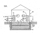
- FIG. 5 illustrating the adaptation of evaporator-separator and evaporator-mixer devices according to the invention to the air conditioning of a dwelling.
- FIG 5 we schematically a building 60 in which we installed an evaporator-mixer EM (or better a battery of such evaporator-mixers mounted-in series) and an evaporator-separator or a battery of such evaporator-separators mounted serial.
- EM evaporator-mixer
- EM evaporator-separator
- a storage tank 61 is provided in which the diluted solution (dilute) is stored at the top at 62, and the concentrated solution (brine) at bottom 63.
- the separation of the two solutions can be done by simple stratification.
- a floating partition wall 64 can also be provided between the two solutions, or one or both of the solutions can also be enclosed in flexible envelopes forming balloons of variable volume, depending on the quantity of each solution.
- the evaporator-mixer will transfer to the sensitive building the same amount of heat but at a higher temperature, for example at 80 ° C, provided that the quantity of concentrated saline solution necessary for its operation is supplied to the evaporator-mixer. This quantity is drawn by the pump 65 from the volume 63 of the tank 61. Obviously, when a concentrated saline solution drawn from the reserve 63 is supplied to the evaporator-mixer, a dilute saline solution (of slightly larger volume) is simultaneously produced upper) which is stored in the tank 62.
- the quantity of heat can be supplied to the evaporator-separator ES at a suitable level, for example at 50 ° C. which will allow the solution to be reconstituted from the saline solution, diluted concentrated saline. Under such conditions, it will suffice to start the pump 66 which will bring the dilute saline solution drawn from the tank 62 to the evaporator-separator battery producing the concentrated saline solution delivered to the tank 63. Simultaneously, water sweet will be produced in 67.
- the evaporator-separator can also operate if desired using any waste heat source, or even electrical heat during off-peak hours.
- FIG. 6 describes an embodiment of a refrigerating panel 79 which is particularly well suited to buildings.
- the panel includes an evaporator-mixer EM and an evaporator-separator ES separated by a volume 78 traversed by a fluid, such as water for example, at ordinary room temperature, for example 20 ° C.
- a fluid such as water for example, at ordinary room temperature, for example 20 ° C.
- the evaporator-separator ES Assuming that the evaporator-separator ES is exposed on the south face S of the building to solar radiation, its external surface can be brought for example to 55 ° C. It is therefore possible in this evaporator-separator to make from a dilute salt solution, a concentrated solution, the evaporated fresh water condensing at the temperature of the cold source (here assumed to be 20 ° C) .
- the evaporator-mixer EM From the concentrated brine produced by the evaporator-separator, it is possible to operate the evaporator-mixer EM by using the inside face of the building as the cold evaporation surface of the evaporator-mixer, the vapor d condensed water being collected as a mixture with the concentrated saline solution on the hot condensing face 78a of the evaporator-mixer EM in contact with the volume 78 (around 20 ° C. in the example illustrated).
- such a refrigerating panel is all the more effective as the exterior surface subjected to solar radiation S will be warmer, which is ideal, the refrigeration being all the more effective as the exterior heat is more intense.
- This panel comprises, like the refrigerating panel 79, an evaporator-mixer EM and an evaporator-separator ES.
- the evaporator-separator ES which is exposed by one of its faces outside the building, but this time on the coldest facade, for example the facade nort that the it is assumed to be brought to -10 ° C.
- This side of the evaporator-separator is obviously the "cold" side, while the hot side is constituted by the wall 81 forming the center of the heating panel 80, which wall is maintained at a temperature in the region of 20 ° C. by a fluid, such as water, constituting the low-level heat source available.
- the wall 81 forming a heat exchanger supplied by the low-level thermal fluid constitutes the heating wall of the evaporator ES
- the exchanger 81 forms a cold part of the evaporator - EM mixer
- Faee Gbaude 82 of the evaporator-mixer EM is directed towards the interior I of the building. If the wall 81b is at around 15-20 ° C., it is easy to obtain, with a single stage of evaporator-mixer and the use of brine, a temperature of the face 82 close to 35 ° C.
- the refrigerating panel of FIG. 6 allows in a way to "pump" into the low-level thermal fluid which has the heat that we want to eliminate Q 3 , Q 4 on the two sides of the panel at two different temperature levels, while in the case of the heating panel in FIG. 7, thermal fluid at a low level which has the quantities of heat Q 3 and Q 4 is extracted, the heat Q 3 at a lower level being eliminated outside, the heat Q 4 at a higher level being used to heat the building.
- a cooling panel 83 essentially composed of an exchanger-mixer EM, an exchanger-separator ES and two heat exchangers 84, 85 supplied respectively by an "ambient" heat source for example at 20 ° C., and by a waste heat source for example at 60 ° C.
- an "ambient" heat source for example at 20 ° C.
- a waste heat source for example at 60 ° C.
- the figure indicates the various temperatures which may exist in each location.
- this panel is quite similar to that of FIG. 6, except that the heat Q 3 is brought to the evaporator-separator ES not by the solar radiation to which the panel was exposed in FIG. 6, but by the heat exchanger 85 using the waste heat fluid around 60 ° C which is supposed to have.
- the evaporator-separator and the evaporator-mixer have a single stage and operate with aqueous saline solutions of the calcium or lithium chloride type; such an installation makes it possible to obtain a cold wall temperature 86 close to 5 ° C., which can constitute an ideal temperature for cold rooms, in particular for the preservation of fruits and vegetables and other foodstuffs. It is clear that such an installation is of design and cost very economical operating costs.
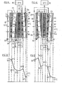
- FIGS. 9 and 10 in which the configuration of a cooler panel of the type described above in FIG. 6 is illustrated more precisely.
- a low-level heat source 87 for example water from a river supposed in the example illustrated at 18 ° C. After crossing the central exchanger 78 of the panel, the water will be discharged in 89 for example at 23 ° C.
- the solar radiation S which heats the exterior face 90 of the building will make it possible to evaporate in the evaporator-separator ES the dilute solution 91 to concentrate it, making it possible to regenerate the brine which will be returned by a pump 92 at the head of the evaporator- EM mixer on the surface of the "hot" plate. 78a of the evaporator-mixer.
- the diluted solution produced in the evaporator-mixer EM at the bottom of the plate 78a is returned by a recycling pump 93 at the top of the plate 90 to feed the film 91 of the diluted solution which will be reconcentrated in the evaporator-separator ES .
- the fresh water collected in the form of film 94 on the "cold" plate 78b of the evaporator-separator ES is also returned to the evaporator-mixer EM to be evaporated on the plate 88 and extract the heat Q 4 at a temperature close to 5 ° C in the example illustrated.
- FIGS 11 and 1 2- illustrate, like Figures 9 and 10, an embodiment of a heater panel operating according to the principle described in Figure 7
- FIG. 13 in la-. which one illustrated the operation of four evaporator-mixers associated in series EM 1 , EM 2 , EM 3 and EM 4. operating for example as it has been described and illustrated in relation to Figures 3 or 5.
- This installation allows extract a quantity of heat Q 1 from a low-level heat source and deliver at a higher level a substantially equivalent quantity of heat Q 2 .
- the installation in order for the installation to function, it must be continuously supplied with the "solvent” used such as for example water and the concentrated “solution” of mixture, such as concentrated brine.
- the solvent supply was identified and in 102 the concentrated solution supply.
- the dilute solution is recovered at 103, that is to say the mixture of the solvent and the concentrated solution.
- each evaporator-separator may be constituted by a solar collector suitably oriented for example on the roof of the building, the surface of all the collectors being able to be substantially equal to that of the panel. heating the building multiplied by the number of evaporator-mixer stages connected in series.
- Such an installation makes it possible to use the solar collectors in the best possible operating conditions while making the operating temperature of these collectors substantially independent of the temperature at which it is ultimately desired to produce the drawn Q 2 heat, essentially at a heat source available at low level.
- the evaporator-separators are solar collectors operating with. the hot side at 55 ° C and the cold side at 20 ° C. Their thermal power density will be limited by celle of solar radiation, for example 500W / m 2 to 1000 W / m 2 .
- the four-stage evaporator-mixer similar to that shown in Figure 3, will deliver heat at 120 ° C (for example in the form of steam or pressurized water) and with a thermal power density of the order from 20 to 30 kilowatts / m 2 .
- the installation presented in FIG. 16 has the double advantage of raising the temperature level of the heat flow which would come from ordinary solar collectors and of concentrating the density of this flow.
- FIGS. 14 and 15 illustrating the application of the invention to the development of high level thermal energy.
- the installation comprises a boiler or combustion chamber CH into which is introduced in 200 the fuel such as fuel for example.
- Combustion in the boiler C H raises the temperature of the hearth for example to 1200-1500 ° C.
- the fumes are sent into the atmosphere through a conduit 201.
- the primary heating fluid f e r is water introduced in 202 at around 20 ° C. for example.
- the water to be heated is not in contact with the hot wall of the boiler CH.
- the hot wall of the boiler is in contact with the face 203 of a first evaporator-separator ES1 which can be of any type described above.
- the face 203 flows the dilute solution or dilute d contained in a storage or collection tank Sd.
- the concentrated solution (or brine) C is collected in a storage tank Sc.
- the solvent is condensed, which has evaporated from the dilute and which is collected in a storage tank 205.
- the diluted solution can be for example an aqueous solution of the water / lithium bromide type which may be 55% in the diluted state and 60% in the concentrated state.
- the temperature diagram is established as illustrated in FIG. 15, the hot wall 203 of the evaporator being brought to 190 ° C., the cold wall in the vicinity of 135 ° C.
- the cold face 204 of the first evaporator-separator stage ES1 is in contact with the hot face of the second stage ES2, which functions like the stage ES1 but between temperatures ranging between 132 ° C., temperature of the hot face 206 , and 95 ° C., temperature of the cold face 207.
- the concentrated solution is collected in parallel with the evaporator-separator ES1. is stored in the tank Sc and the solvent (here de.l'eau) which is collected in the tank 205.
- the cold face 207 of the second evaporator-separator stage ES2 is in contact with the hot face 208 of a third evaporator-separator stage ES3, the cold face of which is at 55 ° C. as shown in the diagram of figure 2.
- This third stage allows fa here again, briquetting from dilute solutions from concentrated solutions c.
- the cold face 209 of the last evaporator-separator stage ES3 serves as a hot exchange surface to heat the water forming the primary fluid 202. Which is thus brought to the outlet of the installation to 50 ° C. as it appears on Figure 1 4 et.sur the temperature diagram of Figure 15. It will be noted that in such an operating diagram, practically, with a few negligible losses, all the amount of heat Q 0 released around 1200 ° C in the CH combustion is released at a temperature of 55 ° C on the heat exchange wall 209 of the last stage of evaporator-separator ES3 to heat the primary water to 50 ° C.
- the amount of heat recoverable in the fumes will essentially depend on their temperature, that is to say that of the hot wall 203 of the first stage of evaporator-separator ES1. This recoverable quantity also depends on the temperature of the water produced, the lower being the latter, the greater being the heat recovered, in particular by condensation of the water vapor contained in the fumes.
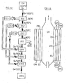
- Figure 16 we will refer to Figure 16 in which we have shown a usage diagram that can correspond to the installation shown schematically in Figure 14.
- This quantity of heat Q 0 is found at the outlet of the evaporator-separator ES1 in a degraded state around 140 ° C at the inlet of the second evaporator-separator ES2, which it in turn crosses to exit at the degraded state around 95 ° C before passing through the third evaporator-separator ES3 from which it finally leaves at 55 ° C and is used at this level to heat the primary fluid, for example water, in the exchanger 211, making it possible to bring the incoming water at 20 ° C to 50 ° C.
- the primary fluid for example water
- the first evaporator-separator ES1 delivers at its outlet a concentrate c brought to a temperature close to 187 ° c ( Figure 15).
- This hot concentrate passes through a heat exchanger EC1 which will allow the diluent d supplied at the head of the separator ES1 to be heated against the current from the storage tank Sd. Except for losses, the quantities of heat required are balanced in the exchanger EC1, which makes it possible to find, at the outlet of the evaporator-separator ES1, the same heat flow Q 0 as the initial flow.
- the cooled brine is stored in the tank Sc.
- the brine storage tank Sc connected to the evaporator circuit ES1 is connected to an evaporator-mixer EM1, and likewise the storage tank for the diluent Sd.
- the evaporator-mixer EM1 When an unmet need for heat arises, it suffices to operate the evaporator-mixer EM1 by supplying it with brine from the reservoir. Sc to which it is connected and in dilute from the reservoir Sd with . which it is linked, as described for example in Figure 1
- a quantity of heat Q 0 can be "pumped" into a low-level source, for example at 20 ° C. and "raised” to be released at 55 ° C so as for example to heat by 20 ° C. at 50 ° C the primary heating water.
- the same can be done in the second EM2 exchanger-mixer fed from the ES2 evaporator-separator and the same can be done from the evaporator EM3 mixer-mixer fed from the ES3 evaporator-separator.
- FIG. 17 another diagram of operation has been illustrated of a boiler CH intended to supply in the illustrated example steam at 110 ° C. produced in a boiler 213.
- the boiler CH does not directly heat the boiler 213, but indirectly through three evaporator-separators ES1, ES2 and ES3 connected in series in which the temperature degrades successively from 230 to 190 ° C, 190 to 150 ° C and 150 to 110 ° C.
- the pressures in these evaporator-separators and the types and concentrations of the solutions are determined in order to have the operating equilibrium conditions required as described above.
- Each of the evaporator-separators ES1, ES2 and ES3 makes it possible to prepare, in a similar manner to what was described above, concentrated solutions from dilute solutions, which solutions are supplied to evaporator-mixers EM1, EM2 and EM3.
- evaporator-mixers EM1, EM2 and EM3 make it possible to prepare, in a similar manner to what was described above, concentrated solutions from dilute solutions, which solutions are supplied to evaporator-mixers EM1, EM2 and EM3.
- FIG. 13 shows that in FIG. 13, four associated evaporator-separators were used in parallel (heated in the hypothesis described by solar radiation) intended to supply four evaporator-mixers in series.
- FIG. 17 there are three evaporator-separators connected in series supplying three evaporator-mixers connected in series.
- FIG. 16 there are three evaporator-separators connected in series supplying three evaporator-mixers connected in parallel.
- FIG. 18 we will now refer to FIG. 18. in which an embodiment of a simplified installation will be described.
- This installation includes a CH ⁇ boiler in which, for example, fuel oil or gas is burned at around 1200-1500 ° C.
- the wall 214 of the boiler which is in contact with the evaporation wall 215 of the evaporator-separator ES is brought to a temperature in the region of 150 to 160 ° C.
- On the wall 215 of the evaporator-separator is brought the solution.
- diluted tion d which is re-centered, the concentrated solution flowing at the bottom of the evaporator-separator while being brought to a temperature in the region of 150 ° C.
- the condensation wall 216 of the evaporator-separator ES is cooled by being in contact with the wall 217 of the heat exchanger 218 in which the primary fluid to be heated, consisting for example of water introduced at around 20 ° C. into the exchanger 218.
- the primary fluid to be heated consisting for example of water introduced at around 20 ° C. into the exchanger 218.
- the water came out at a temperature of 70 ° C., which means that the condensation wall 216 of the evaporator-separator ES is at an average temperature of 75 ° C.
- the vapor pressure in the ES evaporator-separator is of the order of 500 mm of mercury.
- the heat Q 0 released at 1200 ° C. in the combustion chamber of the boiler CH passes through the evaporator ES in which the reconcentration of the diluted solutions d into concentrated solutions c is carried out and is released heat at around 70 ° C in the primary fluid heating chamber 218.
- the concentrated solution c produced in the evaporator-separator ES is brought to the head of the evaporator-mixer EM in contact with the "hot" wall 219 of the evaporator-mixer, assumed here to be brought to an average temperature close to 75 °. vs.
- This concentrated solution absorbs the water vapor evaporated on the "cold" surface 220 of the evaporator-mixer, evaporation which ensures the transfer of the energy taken from the cold source which is assumed, in the example illustrated, to be constituted by water 221 brought to 20 ° C.
- the vapor pressure in the evaporator-mixer EM is approximately 15 mm of mercury. Crossing the evaporator-mixer lowers the temperature of the cold source by approximately 5 ° C, the water therefore entering at 20 ° C and leaving at 15 ° C.
- the installation is completed by a countercurrent heat exchanger 222 which recovers part of the heat from the concentrated solution leaving at 150 ° C from the evaporator-separator to bring it to 85 ° C at the head of the evaporator-mixer, in exchange for the dilute solution d leaving the exchanger-mixer at the temperature of 75 ° C to bring it to the top of the evaporator-separator around 140 ° C.
- Circulation pumps such as 223, 224 complete the installation. Thanks to this arrangement, the heating calorific power of the installation is substantially doubled, the degradation of the noble energy being taken advantage of to allow the extraction of an energy in substantially equivalent quantity drawn from a low temperature source. level.
- a heat recovery unit 225 placed on the smoke circuit will advantageously complete the installation.
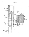
- FIG. 19 the temperatures corresponding to the example given in FIG. 22 are indicated, the enclosure 218 being heated on one side.
- the enclosure 218 being heated on one side.
Landscapes
- Engineering & Computer Science (AREA)
- Physics & Mathematics (AREA)
- Mechanical Engineering (AREA)
- Thermal Sciences (AREA)
- General Engineering & Computer Science (AREA)
- Chemical & Material Sciences (AREA)
- Materials Engineering (AREA)
- Vaporization, Distillation, Condensation, Sublimation, And Cold Traps (AREA)
- Other Air-Conditioning Systems (AREA)
Applications Claiming Priority (4)
| Application Number | Priority Date | Filing Date | Title |
|---|---|---|---|
| FR8017676 | 1980-08-11 | ||
| FR8017676A FR2488379B1 (fr) | 1980-08-11 | 1980-08-11 | Procede et dispositifs pour la revalorisation d'energie thermique a bas niveau mettant en oeuvre des phenomenes d'evaporation et de melange de deux fluides en equilibre de pression de vapeur |
| FR8113846 | 1981-07-16 | ||
| FR8113846A FR2509845B2 (fr) | 1981-07-16 | 1981-07-16 | Procede et dispositifs pour la revalorisation d'energie thermique a bas niveau mettant en oeuvre des phenomenes d'evaporation et de melange de deux fluides en equilibre de pression de vapeur sous des temperatures differentes, et application a la valorisation d'une energie thermique noble |
Related Parent Applications (1)
| Application Number | Title | Priority Date | Filing Date |
|---|---|---|---|
| EP81401260.5 Division | 1981-08-05 |
Publications (3)
| Publication Number | Publication Date |
|---|---|
| EP0148756A2 true EP0148756A2 (de) | 1985-07-17 |
| EP0148756A3 EP0148756A3 (en) | 1986-04-23 |
| EP0148756B1 EP0148756B1 (de) | 1989-03-08 |
Family
ID=26221945
Family Applications (2)
| Application Number | Title | Priority Date | Filing Date |
|---|---|---|---|
| EP81401260A Expired EP0046112B1 (de) | 1980-08-11 | 1981-08-05 | Vorrichtungen und Systeme zum Aufwerten thermischer Energie mit niedrigem Niveau unter Ausnutzung der Verdampfung, und Mischung zweier strömender Medien mit gleichem Dampfdruck bei unterschiedlichen Temperaturen |
| EP85101378A Expired EP0148756B1 (de) | 1980-08-11 | 1981-08-05 | System zum Aufwertem thermischer Energie mit niedrigem Niveau unter Ausnutzung der Verdampfung, und Mischung zweier strömender Medien mit gleichem Dampfdruck bei unterschiedlichen Temperaturen |
Family Applications Before (1)
| Application Number | Title | Priority Date | Filing Date |
|---|---|---|---|
| EP81401260A Expired EP0046112B1 (de) | 1980-08-11 | 1981-08-05 | Vorrichtungen und Systeme zum Aufwerten thermischer Energie mit niedrigem Niveau unter Ausnutzung der Verdampfung, und Mischung zweier strömender Medien mit gleichem Dampfdruck bei unterschiedlichen Temperaturen |
Country Status (3)
| Country | Link |
|---|---|
| US (2) | US4527621A (de) |
| EP (2) | EP0046112B1 (de) |
| DE (1) | DE3173876D1 (de) |
Cited By (1)
| Publication number | Priority date | Publication date | Assignee | Title |
|---|---|---|---|---|
| EP0516758A4 (en) * | 1990-02-27 | 1993-11-24 | Chen-Yen Cheng | Absorption vapor pressure enhancement process and its applications in high level refrigeration and separation processes |
Families Citing this family (15)
| Publication number | Priority date | Publication date | Assignee | Title |
|---|---|---|---|---|
| GB8308137D0 (en) * | 1983-03-24 | 1983-05-05 | Ici Plc | Compression-type heat pumps |
| GB8308135D0 (en) * | 1983-03-24 | 1983-05-05 | Ici Plc | Centrifugal heat pump |
| FR2557277B1 (fr) * | 1983-12-22 | 1986-04-11 | Alsthom Atlantique | Machine a induction thermique |
| GB8400324D0 (en) * | 1984-01-06 | 1984-02-08 | Ici Plc | Heat pumps |
| US4553409A (en) * | 1984-07-12 | 1985-11-19 | Hitachi Zosen Corporation | Multiple regeneration multiple absorption type heat pump |
| FR2591504B1 (fr) * | 1985-12-13 | 1990-04-20 | Centre Nat Rech Scient | Procede d'evaporation-condensation de films ruisselants, elements pour sa mise en oeuvre et ses applications. |
| DE3833666C2 (de) * | 1988-10-04 | 1994-02-17 | Gerd Dr Ing Wilhelm | Verbundsysteme aus normaler und inverser Rektifikation |
| US5291942A (en) * | 1993-05-24 | 1994-03-08 | Gas Research Institute | Multiple stage sorption and desorption process and apparatus |
| FR2754594B1 (fr) * | 1996-10-10 | 1998-12-31 | Gaz De France | Frigopompe |
| FR2756621B1 (fr) * | 1996-11-29 | 1999-02-19 | Gaz De France | Thermo-frigopompe |
| FR2757255B1 (fr) * | 1996-12-13 | 1999-03-05 | Gaz De France | Dispositif a absorption de chaleur et/ou de froid multietagee |
| AU8374098A (en) | 1997-06-18 | 1999-01-04 | Gas Research Institute | Flat-plate absorbers and evaporators for absorption coolers |
| HU0100463D0 (en) * | 2001-01-29 | 2001-03-28 | Szopko Mihaly | Method and device for absorption heat pumping |
| CA2778101A1 (en) * | 2012-05-24 | 2013-11-24 | Jean Pierre Hofman | Power generation by pressure differential |
| CN109681944A (zh) * | 2019-02-13 | 2019-04-26 | 上海虹铂环保科技有限公司 | 一种利用电空气源热水机组深度回收烟气潜化废热组合装置 |
Family Cites Families (23)
| Publication number | Priority date | Publication date | Assignee | Title |
|---|---|---|---|---|
| DE278076C (de) * | 1911-08-11 | |||
| US1683434A (en) * | 1924-01-09 | 1928-09-04 | Siemens Schuckertwerke Gmbh | Method of heating buildings |
| FR675258A (fr) * | 1928-05-18 | 1930-02-07 | Industrikemiska Ab | Procédé et dispositif d'évaporation |
| GB372339A (en) * | 1930-01-09 | 1932-05-02 | Siemens Ag | Utilizing absorption refrigerating machines for heat insulating purposes |
| US1913468A (en) * | 1930-01-09 | 1933-06-13 | Hoover Co | Arrangement for reducing the transmission of heat |
| GB422150A (en) * | 1932-12-21 | 1935-01-07 | Siemens Ag | Improvements relating to heat converters comprising absorption apparatus |
| US2162607A (en) * | 1935-11-20 | 1939-06-13 | American Mach & Foundry | Supply of material in wrapping machines |
| US2182453A (en) * | 1936-01-18 | 1939-12-05 | William H Sellew | Heat transfer process and apparatus |
| FR840283A (fr) * | 1937-07-06 | 1939-04-21 | Perfectionnements apportés aux machines frigorifiques fonctionnant par l'affinité d'un fluide, telque la vapeur d'eau, pour d'autres substances | |
| FR1056314A (fr) * | 1952-02-15 | 1954-02-25 | Procédé et dispositifs concernant les machines frigorifiques à absorption | |
| US3306346A (en) * | 1962-12-03 | 1967-02-28 | Donald F Othmer | Method for cooling volatile liquids |
| DE1444337A1 (de) * | 1963-11-13 | 1968-11-28 | Forsch Ges Verfahrenstechnik E | Verdampfer |
| US3483710A (en) * | 1968-06-13 | 1969-12-16 | Crane Co | Cascade absorption refrigeration system |
| US3822192A (en) * | 1971-12-08 | 1974-07-02 | Aluminum Co Of America | Evaporative method |
| DE2219083C3 (de) * | 1972-04-19 | 1979-08-09 | Doneckij Filial Vnipitschermetenergootschistka, Donezk (Sowjetunion) | Absorptionskälteanlage |
| FR2274564A1 (fr) * | 1974-06-17 | 1976-01-09 | Rigollot Georges | Installation pour la distillation de grandes quantites d'eau |
| US4009575A (en) * | 1975-05-12 | 1977-03-01 | said Thomas L. Hartman, Jr. | Multi-use absorption/regeneration power cycle |
| DE2552538A1 (de) * | 1975-11-22 | 1977-05-26 | Hans Dipl Ing Dr Herrmann | Heizofen mit waermepumpe |
| DE2648855A1 (de) * | 1976-10-25 | 1978-04-27 | Herbst Donald | Einrichtung zur senkung der durch rauchgase bedingten waermeverluste bei einem mit oel oder gas betriebenen heizkessel |
| DE2743488A1 (de) * | 1977-09-28 | 1979-03-29 | Karl Friedrich Prof Dr Knoche | Verfahren und vorrichtung zur nutzung von sonnenenergie fuer raumheizung |
| US4223535A (en) * | 1978-12-22 | 1980-09-23 | Kumm Emerson L | Absorption solar powered air conditioning system with storage capacity |
| DE2939423A1 (de) * | 1979-09-28 | 1981-04-16 | Alefeld, Georg, Prof.Dr., 8000 München | Verfahren zum betrieb einer eine absorber-waermepumpe enthaltenden heizungsanlage und heizungsanlage zur durchfuehrung dieses verfahrens |
| DE3169318D1 (en) * | 1980-03-17 | 1985-04-25 | Hitachi Ltd | System for heat energy conversion |
-
1981
- 1981-08-05 EP EP81401260A patent/EP0046112B1/de not_active Expired
- 1981-08-05 DE DE8181401260T patent/DE3173876D1/de not_active Expired
- 1981-08-05 EP EP85101378A patent/EP0148756B1/de not_active Expired
- 1981-08-07 US US06/291,145 patent/US4527621A/en not_active Expired - Fee Related
-
1984
- 1984-11-29 US US06/658,843 patent/US4606404A/en not_active Expired - Fee Related
Cited By (1)
| Publication number | Priority date | Publication date | Assignee | Title |
|---|---|---|---|---|
| EP0516758A4 (en) * | 1990-02-27 | 1993-11-24 | Chen-Yen Cheng | Absorption vapor pressure enhancement process and its applications in high level refrigeration and separation processes |
Also Published As
| Publication number | Publication date |
|---|---|
| US4527621A (en) | 1985-07-09 |
| US4606404A (en) | 1986-08-19 |
| EP0046112A3 (en) | 1982-09-01 |
| EP0148756A3 (en) | 1986-04-23 |
| EP0046112B1 (de) | 1986-02-26 |
| EP0046112A2 (de) | 1982-02-17 |
| EP0148756B1 (de) | 1989-03-08 |
| DE3173876D1 (en) | 1986-04-03 |
Similar Documents
| Publication | Publication Date | Title |
|---|---|---|
| EP0148756B1 (de) | System zum Aufwertem thermischer Energie mit niedrigem Niveau unter Ausnutzung der Verdampfung, und Mischung zweier strömender Medien mit gleichem Dampfdruck bei unterschiedlichen Temperaturen | |
| TW482743B (en) | Desalination method and desalination apparatus | |
| US20210384865A1 (en) | Method and solar-based system for simultaneous electricity and fresh water generation | |
| EP0072305B1 (de) | Verfahren zum Speichern von mechanischer oder thermischer Energie in Form von chemischer Energie und zur wenigstens teilweisen Rückgewinnung der gespeicherten Energie und Vorrichtung zur Durchführung des Verfahrens | |
| WO2024100030A1 (fr) | Installation de cogeneration electronucleaire a reacteur a eau legere et systeme de capture de co2 atmospherique, ou de dessalement d'eau de mer sans prelevement ou rejet d'eau liquide dans l'environnement | |
| EP0007835B1 (de) | Verfahren zum Trennen eines Gases und eines kondensierbaren Dampfes und seine Anwendungen | |
| EP3667201A1 (de) | Kälteerzeugungssystem, das mit einer kompressionsmaschine, einer absorptionsmaschine und einem thermischen speichersystem zur verbindung der beiden ausgestattet ist | |
| EP3502577B1 (de) | Luftaufbereitungssystem, das eine vorrichtung zur absorption umfasst, und entsprechendes verfahren | |
| FR2488379A1 (fr) | Procede et dispositifs pour la revalorisation d'energie thermique a bas niveau mettant en oeuvre des phenomenes d'evaporation et de melange de deux fluides en equilibre de pression de vapeur | |
| EP3885672B1 (de) | Generator mit einer rektifikationsfunktion, une absorptionsmaschine, die diesen generator umfasst, und ein verfahren zur erzeugung von kältemitteldampf durch den generator | |
| EP3674646B1 (de) | System zur thermochemischen speicherung/freisetzung von energie mit feuchter luft bei einer thermodynamischen dehydratisierungstemperatur, die durch eine entfeuchtungsvorrichtung herabgesetzt ist | |
| WO2014096736A1 (fr) | Dispositif et procede d'evaporation d'un liquide et leurs applications | |
| EP0213038A1 (de) | Durch zwei Fluide in getrennten Kreisläufen durchströmte Wärmetauschvorrichtung | |
| FR2482205A1 (fr) | Centrale de conversion thermodynamique utilisant le rayonnement solaire | |
| FR2509845A2 (fr) | Procede et dispositifs pour la revalorisation d'energie thermique a bas niveau mettant en oeuvre des phenomenes d'evaporation et de melange de deux fluides en equilibre de pression de vapeur sous des temperatures differentes, et application a la valorisation d'une energie thermique noble | |
| FR2754594A1 (fr) | Frigopompe | |
| EP3721151B1 (de) | Verfahren und vorrichtung zur wiederherstellung / umverteilung von thermischer energie durch thermochemischen weg und umverteilungsstation | |
| FR3157377A1 (fr) | Installation et procédé de désalinisation d’eau de mer par évaporation utilisant l’énergie solaire | |
| WO2023222971A1 (fr) | Système de génération de froid et de fourniture d'énergie électrique à partir de l'eau de mer et du soleil | |
| EP4403769A1 (de) | Vorrichtung und verfahren zur erzeugung elektrischer energie | |
| EP4336124A1 (de) | System und verfahren zur übertragung von wärmeenergie | |
| WO2018109287A1 (fr) | Station de production d'energies | |
| EP4403752A1 (de) | System und verfahren zur erzeugung von elektrischer energie | |
| EP3885673A1 (de) | Rektifikationsvorrichtung, die eine rektifikationseinrichtung und eine verteilungsvorrichtung umfasst, und absorptionsmaschine, die diese rektifikationsvorrichtung umfasst | |
| FR2524335A1 (fr) | Distillateur a effets multiples, utilisable notamment pour le dessalement de l'eau de mer et des eaux saumatres au moyen d'energie renouvelable |
Legal Events
| Date | Code | Title | Description |
|---|---|---|---|
| PUAI | Public reference made under article 153(3) epc to a published international application that has entered the european phase |
Free format text: ORIGINAL CODE: 0009012 |
|
| AC | Divisional application: reference to earlier application |
Ref document number: 46112 Country of ref document: EP |
|
| AK | Designated contracting states |
Designated state(s): BE DE GB LU NL SE |
|
| RIN1 | Information on inventor provided before grant (corrected) |
Inventor name: LE GOFF, PIERRE, |
|
| PUAL | Search report despatched |
Free format text: ORIGINAL CODE: 0009013 |
|
| AK | Designated contracting states |
Kind code of ref document: A3 Designated state(s): BE DE GB LU NL SE |
|
| 17P | Request for examination filed |
Effective date: 19860813 |
|
| RAP1 | Party data changed (applicant data changed or rights of an application transferred) |
Owner name: ETABLISSEMENT PUBLIC DIT: CENTRE NATIONAL DE LA R |
|
| 17Q | First examination report despatched |
Effective date: 19870213 |
|
| GRAA | (expected) grant |
Free format text: ORIGINAL CODE: 0009210 |
|
| AC | Divisional application: reference to earlier application |
Ref document number: 46112 Country of ref document: EP |
|
| AK | Designated contracting states |
Kind code of ref document: B1 Designated state(s): BE DE GB LU NL SE |
|
| GBT | Gb: translation of ep patent filed (gb section 77(6)(a)/1977) | ||
| REF | Corresponds to: |
Ref document number: 3176997 Country of ref document: DE Date of ref document: 19890413 |
|
| PLBE | No opposition filed within time limit |
Free format text: ORIGINAL CODE: 0009261 |
|
| STAA | Information on the status of an ep patent application or granted ep patent |
Free format text: STATUS: NO OPPOSITION FILED WITHIN TIME LIMIT |
|
| 26N | No opposition filed | ||
| PGFP | Annual fee paid to national office [announced via postgrant information from national office to epo] |
Ref country code: SE Payment date: 19910717 Year of fee payment: 11 Ref country code: LU Payment date: 19910717 Year of fee payment: 11 |
|
| PGFP | Annual fee paid to national office [announced via postgrant information from national office to epo] |
Ref country code: GB Payment date: 19910730 Year of fee payment: 11 |
|
| PGFP | Annual fee paid to national office [announced via postgrant information from national office to epo] |
Ref country code: BE Payment date: 19910801 Year of fee payment: 11 |
|
| PGFP | Annual fee paid to national office [announced via postgrant information from national office to epo] |
Ref country code: NL Payment date: 19910831 Year of fee payment: 11 |
|
| PGFP | Annual fee paid to national office [announced via postgrant information from national office to epo] |
Ref country code: DE Payment date: 19910925 Year of fee payment: 11 |
|
| EPTA | Lu: last paid annual fee | ||
| PG25 | Lapsed in a contracting state [announced via postgrant information from national office to epo] |
Ref country code: LU Free format text: LAPSE BECAUSE OF NON-PAYMENT OF DUE FEES Effective date: 19920805 Ref country code: GB Effective date: 19920805 |
|
| PG25 | Lapsed in a contracting state [announced via postgrant information from national office to epo] |
Ref country code: SE Effective date: 19920806 |
|
| PG25 | Lapsed in a contracting state [announced via postgrant information from national office to epo] |
Ref country code: BE Effective date: 19920831 |
|
| BERE | Be: lapsed |
Owner name: CENTRE NATIONAL DE LA RECHERCHE SCIENTIFIQUE CNRS Effective date: 19920831 |
|
| PG25 | Lapsed in a contracting state [announced via postgrant information from national office to epo] |
Ref country code: NL Effective date: 19930301 |
|
| GBPC | Gb: european patent ceased through non-payment of renewal fee |
Effective date: 19920805 |
|
| NLV4 | Nl: lapsed or anulled due to non-payment of the annual fee | ||
| PG25 | Lapsed in a contracting state [announced via postgrant information from national office to epo] |
Ref country code: DE Effective date: 19930501 |
|
| EUG | Se: european patent has lapsed |
Ref document number: 85101378.9 Effective date: 19930307 |