EP4403769A1 - Vorrichtung und verfahren zur erzeugung elektrischer energie - Google Patents
Vorrichtung und verfahren zur erzeugung elektrischer energie Download PDFInfo
- Publication number
- EP4403769A1 EP4403769A1 EP23152784.7A EP23152784A EP4403769A1 EP 4403769 A1 EP4403769 A1 EP 4403769A1 EP 23152784 A EP23152784 A EP 23152784A EP 4403769 A1 EP4403769 A1 EP 4403769A1
- Authority
- EP
- European Patent Office
- Prior art keywords
- heat transfer
- transfer fluid
- electrical energy
- turbine
- gaseous state
- Prior art date
- Legal status (The legal status is an assumption and is not a legal conclusion. Google has not performed a legal analysis and makes no representation as to the accuracy of the status listed.)
- Withdrawn
Links
Images



Classifications
-
- F—MECHANICAL ENGINEERING; LIGHTING; HEATING; WEAPONS; BLASTING
- F03—MACHINES OR ENGINES FOR LIQUIDS; WIND, SPRING, OR WEIGHT MOTORS; PRODUCING MECHANICAL POWER OR A REACTIVE PROPULSIVE THRUST, NOT OTHERWISE PROVIDED FOR
- F03G—SPRING, WEIGHT, INERTIA OR LIKE MOTORS; MECHANICAL-POWER PRODUCING DEVICES OR MECHANISMS, NOT OTHERWISE PROVIDED FOR OR USING ENERGY SOURCES NOT OTHERWISE PROVIDED FOR
- F03G6/00—Devices for producing mechanical power from solar energy
- F03G6/003—Devices for producing mechanical power from solar energy having a Rankine cycle
- F03G6/004—Devices for producing mechanical power from solar energy having a Rankine cycle of the Organic Rankine Cycle [ORC] type or the Kalina Cycle type
Definitions
- the present invention relates to the field of energy production and in particular electrical energy. It relates in particular to a device for generating electrical energy from low-temperature thermal energy sources. The invention also relates to a method for generating electrical energy from thermal energy and in particular from low-temperature thermal energy sources.
- thermoelectric materials have the ability to convert thermal energy into electrical energy through the effect known as the Seebeck effect.
- the latter exploits the temperature difference between two materials of different conductivity, which generates a potential difference and therefore an electric current. These materials cannot generate large quantities of energy and are therefore not usable in everyday applications.
- Another way to generate electrical energy from thermal energy is to transform thermal energy into mechanical energy and then convert this mechanical energy into electrical energy.
- This conversion of mechanical energy into electrical energy is commonly carried out in turbines comprising at least one mobile element and an alternator.
- the mobile element such as for example a propeller is set in motion by a flow of material and the mechanical energy is converted into electrical energy by means of the alternator.
- thermal machines which convert thermal energy into mechanical energy require a hot source from which they absorb heat and a cold source into which they reject the share of energy. thermal energy not transformed into mechanical energy. It is estimated today that around 60% of the thermal energy produced is released, particularly into the air. This energy is thus wasted.
- the present invention makes it possible to resolve the problems of the prior art by proposing a device and a method making it possible to generate electrical energy from thermal energy sources, in particular low temperature thermal energy sources, this energy thermal being generally released into the environment without being used.
- a device for generating electrical energy characterized in that it comprises a heat transfer fluid circuit comprising at least one zone in which the heat transfer fluid is in the gaseous state, a compressor arranged to modify the pressure heat transfer fluid in the gaseous state, a turbine arranged to receive heat transfer fluid in the gaseous state, this turbine comprising a device for converting a flow of heat transfer fluid into electrical energy and a heat transfer fluid outlet, and an ejector arranged to receive heat transfer fluid coming on the one hand from said turbine and on the other hand from said compressor.
- the device and the method of the invention make it possible in particular to use sources of thermal energy at low temperature, sources of fatal energy or very generally all sources of thermal energy to produce electrical energy.
- Thermal energy sources may in particular be sources which are often not used because their physical characteristics do not correspond to the needs of existing installations. Such sources may be, for example, cooling water from industrial installations, return liquid from district heating, thermal energy from photovoltaic panels or other types of energy sources generally considered unusable. It is clear that it is also possible to use “conventional” energy sources, in particular electrical energy from photovoltaic panels, hot water from the “flow” liquid of district heating, or thermal energy from thermal solar panels.
- waste energy is energy that would be lost if it were not used when it is available. This energy is often neglected or wasted because it is often produced at a time or place in which it is not useful or usable.
- the present invention makes it possible on the one hand to capture this energy which can be difficult to capture and on the other hand to convert it into electrical energy.
- This electrical energy has the advantage that it can be stored, transported and/or used in a relatively simple, known and controlled manner, minimizing losses compared to other forms of energy.
- renewable energy sources such as thermal energy coming from biomass or the sun in particular, to transform this energy into a form that is easier to store and transport.
- the heat transfer fluid circulating in circuit 11 comprises carbon dioxide CO 2 .
- CO 2 carbon dioxide
- the latter is interesting as a heat transfer fluid for several reasons. At the temperatures in which it is typically used, it does not change to a solid state, unlike water in particular. It is therefore not necessary to take special precautions to prevent it from assuming this state of matter. Furthermore, by choosing an appropriate combination of pressure and temperature, it is possible to use the phase transition between the gaseous state and the liquid state of carbon dioxide. This phase transition allows a release or capture of a large amount of energy without a change in temperature.
- volume enthalpy or specific enthalpy The quantity of energy per unit of volume or mass (volume enthalpy or specific enthalpy) is much greater in the case where this energy comes from a phase change between liquid CO 2 and gaseous CO 2 than in the case where it comes from a change in water temperature.
- the diameter of the tubes in which the heat transfer fluid circulates may be significantly smaller in the case where this heat transfer fluid is CO 2 than in the case where it is water, for the transport of a same amount of energy. This results in particular in a simplified installation.
- CO 2 is not toxic, is found in abundant quantities and the costs associated with its use are relatively low.
- other heat transfer fluids are not excluded. It is indeed possible to use heat transfer fluids having equivalent properties, and in particular mixtures of different fluids.
- the heat transfer fluid can circulate in different states of matter in different areas of the circuit.
- the heat transfer fluid in a first zone 11a, the heat transfer fluid is in the gaseous state.
- the heat transfer fluid in a second zone 11b of the circuit, can be in the liquid state.
- the vaporization device 15 establishes a material junction between the two zones and makes it possible to transform the liquid carbon dioxide into gaseous carbon dioxide. This state of the material obviously depends on the pressure and temperature of the heat transfer fluid in the different zones of the circuit.
- the compressor 12 is arranged in the heat transfer fluid circuit and has an inlet 12a and an outlet 12b.
- the inlet 12a of this compressor receives heat transfer fluid in the gaseous state at a first pressure which is here called intermediate pressure. This pressure can generally be between 50 and 80 bars.
- the compressor 12 is arranged to increase the pressure of the gaseous heat transfer fluid.
- the outlet 12b is arranged to introduce heat transfer fluid into the circuit at a pressure greater than said intermediate pressure. This outlet pressure is referred to here as “high pressure”. It is generally between 100 and 150 bars.
- the compressor 12 operates with a power supply.
- This power supply can be an independent source; it can be a source connected to the generation device of the invention, such as for example a photovoltaic solar panel.
- the electrical energy necessary for the operation of the compressor can be taken directly from turbine 14.
- the ejector 13 is also arranged in the heat transfer fluid circuit 11 and has two inlets 13a, 13b and an outlet 13c.
- One of the inlets 13b of the ejector is physically connected to the vaporization device 15, the operation of which is described in detail below.
- This inlet 13b receives heat transfer fluid at a pressure lower than the “intermediate pressure” mentioned above. This pressure is referred to here as “low pressure”.
- the other inlet 13a of the ejector is materially connected to the outlet 12b of the compressor 12. This inlet 13a of the ejector thus receives gaseous heat transfer fluid at high pressure.
- the high pressure heat transfer fluid creates a vacuum in the ejector 13 and compresses the low pressure heat transfer fluid to produce intermediate pressure heat transfer fluid.
- This heat transfer fluid at intermediate pressure exits through the outlet 13c of the ejector 13 into the heat transfer fluid circuit.
- the turbine 14 has an inlet 14a connected to zone 11a of the circuit in which the heat transfer fluid circulates in gaseous form. More precisely, the inlet 14a of the turbine is arranged to receive gaseous CO 2 at high pressure.
- the turbine 14 also includes an outlet 14b making it possible to evacuate the heat transfer fluid from this turbine.
- the latter also includes a chamber connecting the inlet 14a to the outlet 14b and containing a movable element (not shown) which can be set in motion by a flow of heat transfer fluid circulating between the inlet and the outlet.
- the moving element can typically be a propeller, although other elements could be considered.
- the turbine further comprises an alternator (not shown) whose function is to convert the mechanical energy of the movement of the mobile element into electrical energy.
- the outlet 14b of the turbine is materially connected to the vaporization device 15.
- This vaporization device 15 receives heat transfer fluid leaving the turbine 14.
- This heat transfer fluid is in the liquid state in the embodiments illustrated by the figures 1 to 4 .
- it could also be found in the form of a mixture of gaseous CO 2 and liquid CO 2 as represented by the figures 5 And 7 .
- the carbon dioxide exiting the turbine could also be completely in a gaseous state, as illustrated by the Figure 6 .
- the function of the vaporization device 15 is to return the carbon dioxide to the gaseous state.
- the heat transfer fluid entering the vaporization device 15 from the turbine 14 is heated until it reaches this state of the matter.
- the energy used to heat this heat transfer fluid can come from different sources. For example, it is possible to use one or more thermal solar panels or to draw energy from building walls, cooling water or any other suitable source. Other types of energy, such as electrical energy in particular, could also be used.
- the electrical energy generation device 10 operates in the form of a cycle.
- the cycle is described from the ejector 13.
- the ejector receives on the one hand carbon dioxide in the gaseous state at high pressure and on the other hand gaseous carbon dioxide at low pressure. These gases are mixed in the ejector 13. Gaseous carbon dioxide at intermediate pressure emerges.
- This carbon dioxide is then sent to the compressor 12 in which it is compressed so as to obtain carbon dioxide at high pressure.
- Part of the high pressure carbon dioxide is sent to the inlet of the turbine 14 and another part is returned to the inlet 13a of the ejector 13. In this zone of the circuit, the carbon dioxide is found at the gaseous state.
- the part of the high pressure carbon dioxide sent to the inlet 14a of the turbine 14 is used to generate mechanical energy, in particular by the movement of the movable member of this turbine.
- the turbine's alternator then converts the mechanical energy into electrical energy.
- the latter can be used in part to operate the compressor 12. It can also be transmitted to a consumer of electrical energy, in a network or in a storage device in particular.
- the heat transfer fluid introduced into the turbine 14 undergoes expansion and therefore cooling. This cooling can cause a phase change in the heat transfer fluid, which goes from the gaseous state to the liquid state. Depending on the conditions of use, it is possible for the heat transfer fluid to be in the state of a gaseous and liquid mixture or to remain in the gaseous state.
- the heat transfer fluid leaving the turbine 14 is sent to the vaporization device 15 in which it is heated to be converted into gaseous carbon dioxide, which is itself used as the input gas in the ejector 13.
- the device of the invention can be powered by different energy sources.
- this device makes it possible to recover energy from sources which are often not used as indicated above.
- sources may include cooling water from industrial installations, return liquid from district heating, thermal energy from photovoltaic panels or other types of energy sources. generally considered unusable, as are conventional energy sources such as electrical energy from photovoltaic panels, hot water from the “go” liquid of district heating, or thermal energy from solar panels thermal.
- one of the energy sources could be an outlet conduit of a district heating device and have a temperature between 70°C and 90°C.
- the other energy source could be a return duct from the district heating device and have a temperature between 25°C and 50°C.
- FIG. 1 illustrates an embodiment in which the device of the invention uses as an energy source, a thermal solar panel 16 intended to recover solar energy and convert it into electrical energy.
- the electrical energy necessary to operate the compressor 12, if applicable, is a part of the electrical energy produced by the turbine 14.
- the thermal energy necessary to operate the vaporization device 15 comes from the thermal solar panel.
- the device of the invention thus makes it possible to convert thermal energy recovered by the thermal solar panel(s) into electrical energy, simply and efficiently. In addition, this installation is simple and inexpensive to set up.
- the energy source of the device of the invention is a photovoltaic solar panel 17. This panel produces a certain quantity of electrical energy which can be used in particular to power the compressor 12.
- photovoltaic solar panels also generate thermal energy.
- This thermal energy is often unused, particularly due to the difficulty of transporting and/or storing it.
- this thermal energy is used in the vaporization device 15 to vaporize the liquid heat transfer fluid into gaseous heat transfer fluid, before the entry of the ejector 13.
- the transfer of this thermal energy into the vaporization device 15 can be done in particular by means of a heat exchanger (not shown) which makes it possible to transfer energy without transfer of material.
- the energy produced by the photovoltaic solar panel is used optimally, whether this energy is electrical or thermal. It therefore significantly improves the performance of a photovoltaic installation.
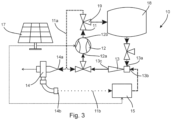
- the circuit 11 of gaseous heat transfer fluid comprises a storage element 18 of gaseous carbon dioxide at high pressure. More precisely, the output 12b of the compressor 12 is materially connected to a valve 19, for example a three-way valve, one of the channels of which is materially connected to the storage element 18. By means of this three-way valve, it is possible to choose to send the gaseous carbon dioxide at high pressure into the turbine 14 or into the storage element 18.
- This storage element 18 is materially connected to the ejector 13, so that the high pressure carbon dioxide entering the ejector 13 is taken from the storage element 18 and not or not necessarily from the outlet 12b of the compressor . This storage element facilitates the management of carbon dioxide flows throughout the circuit.
- the output 12b of the compressor is also physically connected to the input 12a of this compressor by means of a valve.
- part of the high pressure gaseous heat transfer fluid which is not used in the turbine 14 can be reinjected into the compressor 12.
- This also makes it possible to facilitate and optimize the carbon dioxide flows overall. of the circuit and adapt these flows dynamically, according to needs and available resources.
- zone 11a of the circuit in which the heat transfer fluid circulates in the gaseous state comprises a heat exchanger 20, here called a heating heat exchanger. More precisely, at the outlet of the compressor 12, the gaseous heat transfer fluid at high pressure is introduced into the heating heat exchanger 20 in which it transfers part of its energy to a consumer.
- This consumer can typically be a domestic heating system, a domestic hot water production element, or other similar systems.
- the heating heat exchanger 20 receives cold water as an inlet from one side of the heat exchanger. This cold water is heated by the high pressure gaseous heat transfer fluid circulating on the other side of the heat exchanger so that hot water comes out of this heat exchanger.
- carbon dioxide On the other side of the heat exchanger, that is to say on the side in which gaseous carbon dioxide circulates, carbon dioxide enters at a high temperature and leaves, after having given up part of its energy thermal, at a lower temperature.
- One of the outlets of the heating heat exchanger 20 is connected to the inlet 14a of the turbine 14 and to the inlet 12a of the compressor 12, as in the embodiment illustrated by the Figure 3 .
- the embodiment illustrated by Figure 5 is partly similar to the embodiment illustrated by figure 1 .
- the outlet 14b of the turbine 14 contains not only liquid carbon dioxide, but also gaseous carbon dioxide at low pressure. Liquid carbon dioxide and gaseous carbon dioxide are separated from each other.
- the liquid carbon dioxide is sent to the vaporization device 15 as in the embodiments described above.
- the gaseous carbon dioxide at low pressure is introduced into a compression device 21 which has the function of increasing the pressure of this carbon dioxide.
- the final pressure at the outlet of this compression device 21 can be of the same order of magnitude as the pressure obtained at the outlet of the vaporization device 15.
- This gaseous carbon dioxide can then be mixed with the carbon dioxide leaving the vaporization device 15 and /or be introduced into the ejector 13.
- This variant thus makes it possible to advantageously manage the cases in which the turbine 14 supplies liquid carbon dioxide and gaseous carbon dioxide.
- FIG. 6 illustrates an embodiment in which the heat transfer fluid leaving the turbine 14 is exclusively in the gaseous state and not in the liquid state.
- the heat transfer fluid leaving this turbine is sent to the compression device 21 arranged to compress the gaseous heat transfer fluid at low pressure leaving the turbine so that this heat transfer fluid reaches a pressure compatible with its use in the ejector.
- This pressure can typically be less than 40 bars. It can be of the same order of magnitude as the pressure of the heat transfer fluid in the gaseous state leaving the vaporization device 15 as described in the previous embodiments.
- the turbine 14 delivers carbon dioxide in the liquid state and in the gaseous state.
- the liquid portion of this carbon dioxide is transmitted to the vaporization device 15 as in the previous embodiments.
- the gaseous portion of this carbon dioxide is transmitted to a first inlet of a heat exchanger, called cooling heat exchanger 22.
- This cooling heat exchanger comprises a first outlet communicating with the first inlet, this first outlet being connected materially to the compression device 21.
- the cooling heat exchanger 22 has a second inlet and a second outlet materially connected to each other.
- the hydraulic circuit connecting the first inlet to the first outlet is thermally connected to the hydraulic circuit connecting the second inlet to the second outlet, these two circuits being however materially separated, so that they can exchange heat, without exchange material.
- a heat transfer fluid such as water, carbon dioxide, air or another suitable heat transfer fluid is introduced into the cooling heat exchanger 22 via its second inlet, at a temperature higher than the temperature of the carbon dioxide gas coming from the turbine 14.
- This hot heat transfer fluid gives up part of its energy to the carbon dioxide and therefore leaves the cooling heat exchanger 22 at a temperature lower than the temperature d 'entrance.
- This embodiment thus makes it possible to generate electrical energy in a manner similar to the embodiments illustrated by the previous figures, while also making it possible to supply cold to a consumer.
- the heat transfer fluid leaving the turbine can be in the liquid state exclusively, in the gaseous state exclusively or in the form of a mixture of liquid and gaseous heat transfer fluid. It is possible to choose the state in which the heat transfer fluid leaves the turbine 14 by choosing the operating conditions of the system, in particular the different pressures and temperatures of the heat transfer fluid in the different zones of the circuit.
- the turbine can also be adapted or chosen to operate with a heat transfer fluid in the gaseous state only, in the liquid state only or in both the liquid and gaseous states.
- certain embodiments described comprise thermal solar panels while others comprise photovoltaic solar panels.
- Some embodiments include storage elements, low pressure carbon dioxide gas recovery circuits and/or one or more heat exchangers. These elements can be interchanged or combined with each other, as long as these combinations make sense from a technical point of view.
- the device of the invention has been described with carbon dioxide as heat transfer fluid. Particularly for the reasons indicated above, the latter is interesting due to its properties. However, other heat transfer fluids are not excluded. It is in fact possible to use heat transfer fluids having equivalent properties, and in particular mixtures of different fluids.
Landscapes
- Engineering & Computer Science (AREA)
- Chemical & Material Sciences (AREA)
- Combustion & Propulsion (AREA)
- Life Sciences & Earth Sciences (AREA)
- Sustainable Development (AREA)
- Sustainable Energy (AREA)
- Mechanical Engineering (AREA)
- General Engineering & Computer Science (AREA)
- Engine Equipment That Uses Special Cycles (AREA)
Priority Applications (1)
| Application Number | Priority Date | Filing Date | Title |
|---|---|---|---|
| EP23152784.7A EP4403769A1 (de) | 2023-01-20 | 2023-01-20 | Vorrichtung und verfahren zur erzeugung elektrischer energie |
Applications Claiming Priority (1)
| Application Number | Priority Date | Filing Date | Title |
|---|---|---|---|
| EP23152784.7A EP4403769A1 (de) | 2023-01-20 | 2023-01-20 | Vorrichtung und verfahren zur erzeugung elektrischer energie |
Publications (1)
| Publication Number | Publication Date |
|---|---|
| EP4403769A1 true EP4403769A1 (de) | 2024-07-24 |
Family
ID=85036409
Family Applications (1)
| Application Number | Title | Priority Date | Filing Date |
|---|---|---|---|
| EP23152784.7A Withdrawn EP4403769A1 (de) | 2023-01-20 | 2023-01-20 | Vorrichtung und verfahren zur erzeugung elektrischer energie |
Country Status (1)
| Country | Link |
|---|---|
| EP (1) | EP4403769A1 (de) |
Citations (3)
| Publication number | Priority date | Publication date | Assignee | Title |
|---|---|---|---|---|
| DE10228865A1 (de) * | 2002-06-27 | 2004-01-15 | Uehlin, Jürgen, Dipl.-Ing. | Kollektor mit integrierter Expansionsmaschine und Generator zur Wandlung thermischer Solarstrahlung in Elektrizität |
| WO2012131021A2 (en) * | 2011-04-01 | 2012-10-04 | Nuovo Pignone S.P.A. | Organic rankine cycle for concentrated solar power system with saturated liquid storage and method |
| US11480160B1 (en) * | 2021-11-16 | 2022-10-25 | King Fahd University Of Petroleum And Minerals | Hybrid solar-geothermal power generation system |
-
2023
- 2023-01-20 EP EP23152784.7A patent/EP4403769A1/de not_active Withdrawn
Patent Citations (3)
| Publication number | Priority date | Publication date | Assignee | Title |
|---|---|---|---|---|
| DE10228865A1 (de) * | 2002-06-27 | 2004-01-15 | Uehlin, Jürgen, Dipl.-Ing. | Kollektor mit integrierter Expansionsmaschine und Generator zur Wandlung thermischer Solarstrahlung in Elektrizität |
| WO2012131021A2 (en) * | 2011-04-01 | 2012-10-04 | Nuovo Pignone S.P.A. | Organic rankine cycle for concentrated solar power system with saturated liquid storage and method |
| US11480160B1 (en) * | 2021-11-16 | 2022-10-25 | King Fahd University Of Petroleum And Minerals | Hybrid solar-geothermal power generation system |
Similar Documents
| Publication | Publication Date | Title |
|---|---|---|
| EP3732743B1 (de) | Energieerzeugungsanlage mit kopplung einer brennstoffzelle und eines reversiblen thermodynamischen systems | |
| FR3056230A1 (fr) | Systeme d'electrolyse reversible de l'eau a haute temperature comportant un reservoir d'hydrures couple a l'electrolyseur | |
| FR3011626A1 (fr) | Systeme thermodynamique de stockage/production d'energie electrique | |
| EP1672270A2 (de) | Anlage zum Verdichten und Verdampfen von Flüssiggasen | |
| FR2929381A1 (fr) | Installation pour la production de froid, de chaleur et/ou de travail | |
| FR2947015A1 (fr) | Regulation de la temperature d'un regenerateur thermique utilise dans une installation de stockage d'energie par compression adiabatique d'air. | |
| FR2940355A1 (fr) | Dispositif de production d'electricite avec plusieurs pompes a chaleur en serie | |
| FR3014182A1 (fr) | Systeme avance de stockage d'energie par air comprime | |
| WO2013057427A1 (fr) | Stockage adiabatique ameliore d'energie sous forme de chaleur et d'air comprime. | |
| EP0148756A2 (de) | System zum Aufwertem thermischer Energie mit niedrigem Niveau unter Ausnutzung der Verdampfung, und Mischung zweier strömender Medien mit gleichem Dampfdruck bei unterschiedlichen Temperaturen | |
| FR2640322A1 (fr) | Moteur-fusee ou moteur combine pour vehicule spatial a circuit hydraulique auxiliaire essentiellement ferme | |
| EP4403769A1 (de) | Vorrichtung und verfahren zur erzeugung elektrischer energie | |
| EP3191693B1 (de) | System zur stromerzeugung basierend auf einem rankine-prozess | |
| BE903196A (fr) | Procede de production d'energie | |
| EP4403752A1 (de) | System und verfahren zur erzeugung von elektrischer energie | |
| EP4403835A1 (de) | System und verfahren zum transport und zur verteilung von energie | |
| EP4403751A1 (de) | Stromerzeugungssystem und stromerzeugungsverfahren | |
| CA3142977A1 (fr) | Dispositif thermodynamique haut rendement hybride solaire et couple hydrogene-oxygene produisant une pluralite d'energies | |
| CA3173293C (fr) | Systeme de compression thermique d'un gaz | |
| EP4330603B1 (de) | Wärmepumpe und phasenwechselenergiespeichervorrichtung | |
| WO2025191010A1 (fr) | Pompe à chaleur à très haute température et procédé de production de chaleur à très haute température | |
| FR3117167A1 (fr) | procédé de stockage et de récupération d’énergie avec optimisation thermique à la détente | |
| WO2022117407A1 (fr) | Système et procédé de stockage et de récupération d'énergie par gaz comprimé avec cycle de rankine | |
| WO2025078759A1 (fr) | Système de refroidissement d'un gaz chargé en dioxyde de carbone | |
| FR3130855A1 (fr) | Système combiné de production et de compression du dihydrogène |
Legal Events
| Date | Code | Title | Description |
|---|---|---|---|
| PUAI | Public reference made under article 153(3) epc to a published international application that has entered the european phase |
Free format text: ORIGINAL CODE: 0009012 |
|
| STAA | Information on the status of an ep patent application or granted ep patent |
Free format text: STATUS: THE APPLICATION HAS BEEN PUBLISHED |
|
| AK | Designated contracting states |
Kind code of ref document: A1 Designated state(s): AL AT BE BG CH CY CZ DE DK EE ES FI FR GB GR HR HU IE IS IT LI LT LU LV MC ME MK MT NL NO PL PT RO RS SE SI SK SM TR |
|
| STAA | Information on the status of an ep patent application or granted ep patent |
Free format text: STATUS: THE APPLICATION IS DEEMED TO BE WITHDRAWN |
|
| 18D | Application deemed to be withdrawn |
Effective date: 20250125 |