EP0149094B1 - Aufzeichnungsgerät für zeitlichgeraffte EKG-Signale - Google Patents
Aufzeichnungsgerät für zeitlichgeraffte EKG-Signale Download PDFInfo
- Publication number
- EP0149094B1 EP0149094B1 EP84114675A EP84114675A EP0149094B1 EP 0149094 B1 EP0149094 B1 EP 0149094B1 EP 84114675 A EP84114675 A EP 84114675A EP 84114675 A EP84114675 A EP 84114675A EP 0149094 B1 EP0149094 B1 EP 0149094B1
- Authority
- EP
- European Patent Office
- Prior art keywords
- data
- ecg
- stored
- group
- values
- Prior art date
- Legal status (The legal status is an assumption and is not a legal conclusion. Google has not performed a legal analysis and makes no representation as to the accuracy of the status listed.)
- Expired - Lifetime
Links
Images
Classifications
-
- A—HUMAN NECESSITIES
- A61—MEDICAL OR VETERINARY SCIENCE; HYGIENE
- A61B—DIAGNOSIS; SURGERY; IDENTIFICATION
- A61B5/00—Measuring for diagnostic purposes; Identification of persons
- A61B5/24—Detecting, measuring or recording bioelectric or biomagnetic signals of the body or parts thereof
- A61B5/316—Modalities, i.e. specific diagnostic methods
- A61B5/318—Heart-related electrical modalities, e.g. electrocardiography [ECG]
- A61B5/333—Recording apparatus specially adapted therefor
- A61B5/338—Recording by printing on paper
-
- A—HUMAN NECESSITIES
- A61—MEDICAL OR VETERINARY SCIENCE; HYGIENE
- A61B—DIAGNOSIS; SURGERY; IDENTIFICATION
- A61B5/00—Measuring for diagnostic purposes; Identification of persons
- A61B5/72—Signal processing specially adapted for physiological signals or for diagnostic purposes
- A61B5/7232—Signal processing specially adapted for physiological signals or for diagnostic purposes involving compression of the physiological signal, e.g. to extend the signal recording period
Definitions
- This invention relates to a method of printing an analog waveform having a time variable such as, in particular, a highly space-compressed train of electrocardiograph (ECG) waveforms, here termed a miniature ECG.
- a time variable such as, in particular, a highly space-compressed train of electrocardiograph (ECG) waveforms, here termed a miniature ECG.
- Patent 4,214,590 describes a technique of recording ECG signals onto tape and then transcribing that data onto hard copies in a compressed format.
- the recording per se utilizes a conventional endless loop with stylii controlled by galvanometers to perform the actual tracing.
- tracing proceeds along an axis parallel to the direction of movement of the paper.
- the time axis is the direction of paper movement.
- Chart speed is in the range of 25 mm/sec with the stylus having the ability to denote of the order of ⁇ 2.5 millivolts of heart electrical activity. Consequently, the '505 reference utilizes a standard graphical output of electrocardiographic data, albeit eliminating that which appears to be redundant.
- FR-A 2 353 267 Another electro-cardiographic system is known by FR-A 2 353 267.
- the measured input signals are stored in a digital memory after their conversion into a time sequence of digitally expressed values.
- the stored signals are readout from the memory and reconverted into analog form to control a CRT display device.
- the stored signals are transferred via an optical coupler and a decoder to printing electrodes which produce a graphic representation by marking corresponding dots on a sheet of paper which is moved along the electrodes during the printing process.
- the principal advantage of the thermal printhead or equivalent linear array technology, when combined with appropriate data compression, is the very high speed with which, compared to galvanometer output, a large volume of ECG data can be graphically presented.
- One minute of diagnostic high resolution galvanometer recorded ECG data takes one minute to plot; with the invention here described, the time to plot a minute of compressed ECG data can be significantly less than one second.
- recording occurs on a single sheet of (for example) 21,6 cmx27,94 cm paper or on portions of a roll of indefinite length.
- ECG data in analog form is obtained utilizing conventional sensors followed by A/D conversion and the storage of the thus generated ⁇ digital values.
- the stored values are further processed and the result gated appropriately in time to a linear array of fixed printing elements, for example a linear dot array printhead operated for parallel output in a timed relationship with a chart feed moving perpendicular to the linear array.
- the activation of a particular print element in the array is a function of the maximum and minimum ECG sample values occurring within the ECG time interval corresponding to the position of that print element within the linear array.
- the beginning and end of the period of energizing a particular print element by virtue of the timed relationship of the print commands to the chart feed, provides a line along the direction of the chart motion which, in length and position, represents the spread of values of the pair of ECG samples from which the activation information for that print element is derived.
- an ECG wave may be sampled in a process of analog to digital (A/D) conversion at a sampling rate of k samples per second.
- A/D analog to digital
- This invention provides means for A/D conversion of an analog ECG wave train, for segregating successive groups of samples, for determining the maximum and minimum sample values for each group, and for serially storing in a memory the values of the max-min pair associated with each group and thus with each print element.
- the memory is filled (i.e. all ECG print elements have assigned pair values)
- the stored data is "read out” effectively in parallel by activating and de-activating the print elements as a function of their associated stored max-min pair .values and of the position of the mechanical drive that moves the recording medium across the linear printhead array.
- a long duration train of heart cycle electrical waveforms is recorded as a succession of short parallel lines transverse to the axis of the printhead; the aggregate of the transverse lines represents with low resolution the basic timing and amplitude information of the input long-duration high resolution waveform train.
- the maximum and minimum amplitudes may be modified to prevent recording gaps which may exist.
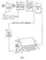
- the present invention utilizes a thermal print head 10, for example a linear dot array printer, of the type sometimes used as a computer output printer.
- the linear array thermal printer 10 has a number of elements N, typically 39 per linear cm and by selective energizing of elements a thermally sensitive paper 12 is provided with an array of dots to provide a visual record of the data to be recorded.
- Such linear array printers are well known in the technology.
- a platen 14 is disposed below the paper 12 to provide a backing for the thermal print head to achieve uniform contact of the print elements to the paper.
- the paper 12 is fed from a roll 16 and is driven in a direction of the arrow shown in Figure 1 in any conventional manner, for example, by pressure rollers, movement of the platen 14, sprockets or the like.
- any element of the printhead is electrically actuated, a visible dot is formed on the thermal paper. If the same element is repeatedly actuated, the summation of printed dots forms a line or bar placed parallel to the direction of paper travel, that is in the direction of paper movement.
- the present invention uses the advantages of this conventional technology, a large number of individually activated print elements in a linear array, to print a miniature ECG at a resolution that is low but yet sufficient to allow for diagnosis of arrhythmias.
- the present invention employs this known technology to construct a compressed ECG.
- the width of the paper 12 is a standard 21,6 cmx27,94 cm page
- one hour of ambulatory ECG recording can be accomplished requiring 60 lines each representing one minute of ECG data.
- the amount of "fan-fold" or roll paper paper that would be required for the same recording at the normal diagnostic 25 mm/sec rate is quite large by comparison (about 90 meters).
- a typical currently available thermal linear array printhead utilizes approximately 800 elements within an 8 inch width, thus achieving a density of 100 elements/inch. If, for example, one minute of data were to be printed on the line having 800 elements, this ⁇ would utilize an average of 13.33 print elements per second of ECG data. The resulting resolution is below that conventionally used to represent and plot data (100-500 samples/sec as set forth in U.S. Patent 4,090,505).
- an acceptable mini-ECG may be generated utilizing this small linear print density by employing available printhead technology. That is, the present invention does not require galvanometers of extreme accuracy to drive movable stylii as in conventional diagnostic ECG recording.
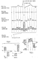
- FIG. 2A consider first an input continuous analog ECG signal and an array of samples shown in Fig. 2A. Each dot represents a discrete sampling point derived from the waveform of Fig. 2A.
- Fig. 2B denotes time intervals each representing the time span allocated to an individual printhead element of the linear array printhead 10. Successive intervals shown in Fig. 2B therefore correspond to successive groups of samples shown by the dots in Fig. 2A. It will be appreciated that there may be many samples contained in each interval.
- Fig. 2C represents a plot wherein for each interval maximum and minimum samples are retained.
- one point is retained since the maximum and minimum values are the same.
- two sample points are retained.
- the retained sampling points are both positive.
- the sampling points are a positive point and a negative point respectively.
- the values of the pairs of maximum and minimum points shown in 2C are used to activate each element of the printhead 10 to produce a series of vertical bars which will represent the ECG.
- Fig. 2E represents a portion of a mini-ECG generated utilizing the method disclosed relative to Figs. 2A-2D and plotted with a more realistically compressed time axis. It is understood that at a printing density of 39 elements/cm the bars would appear to be touching, thereby defining a transverse waveform.
- Such an ECG is suitable for arrhythmia diagnosis from an ambulatory ECG, that is one taken over a long duration of time from a patient under study as that individual goes about his daily activities.
- ECG data provides an analog input with generally five distinct waveform portions produced during each normal heart cycle.
- Fig. 1 portrays a system for printing a wave train composed of many successive heart cycles on each line across the page.
- Input data is first subjected to analog to digital conversion in converter 20.
- the clock 22 provides the conversion frequency rate input, an f1.
- the thus converted digital data is then partitioned by the circuits of the short group buffer 24 at a uniform rate f2 into sequential groups of values that are then processed by the circuits of the max-min compare 25 to select the maximum and minimum value pair for each group; that is data fills the short group buffer 24 in an amount corresponding to the number of dots shown in Fig.
- Fig. 3 represents an overlay showing the sampling points of Fig. 2A as a result of A/D conversion of an analog ECG input.
- the bars shown in Fig. 3 represents those which would be printed as a result of maximum and minimum samples obtained within two adjacent intervals.
- the individual sample points are also shown in Fig. 3.
- a gap may exist between successive bars that would be printed thereby resulting in a gap of the printed ECG. In accordance with the present invention, such recording gaps can be prevented.
- Fig. 4 shows two cases. In the first, a gap exists since the minimum value B, is greater than the maximum value T 2 . In the second case, the maximum value of T, is less than the minimum value of B 2 , thereby resulting in a gap.
- a further advantage of the present invention is that the same linear array printhead can be used to print alphanumeric characters on the data sheet 12. Consequently, by utilizing any suitable drive and character generator logic, well known in the technology, annotations can be added to the illustrated mini ECG to provide various descriptor data, such as patient name, patient number, date and the like.
- the present invention provides parallel plotting of miniature ECG wave trains for significant data compression of the input analog ECG wave sequences.
- the entire ECG wave train is plotted in parallel with the ECG time axis at right angles to the paper motion. This orientation is therefore orthogonal to that used in most diagnostic ECG plotting systems wherein the paper motion axis is used as the ECG time axis.
- printers may be employed so long as sufficient print element density is maintained.
Landscapes
- Health & Medical Sciences (AREA)
- Life Sciences & Earth Sciences (AREA)
- Engineering & Computer Science (AREA)
- Animal Behavior & Ethology (AREA)
- Public Health (AREA)
- Pathology (AREA)
- Physics & Mathematics (AREA)
- Biomedical Technology (AREA)
- Heart & Thoracic Surgery (AREA)
- Medical Informatics (AREA)
- Molecular Biology (AREA)
- Surgery (AREA)
- Veterinary Medicine (AREA)
- General Health & Medical Sciences (AREA)
- Biophysics (AREA)
- Cardiology (AREA)
- Artificial Intelligence (AREA)
- Computer Vision & Pattern Recognition (AREA)
- Physiology (AREA)
- Psychiatry (AREA)
- Signal Processing (AREA)
- Measurement And Recording Of Electrical Phenomena And Electrical Characteristics Of The Living Body (AREA)
- Recording Measured Values (AREA)
- Dot-Matrix Printers And Others (AREA)
- Record Information Processing For Printing (AREA)
Claims (13)
Applications Claiming Priority (2)
| Application Number | Priority Date | Filing Date | Title |
|---|---|---|---|
| US06/565,499 US4509530A (en) | 1983-12-27 | 1983-12-27 | System for plotting a miniature ECG |
| US565499 | 1990-08-10 |
Publications (3)
| Publication Number | Publication Date |
|---|---|
| EP0149094A2 EP0149094A2 (de) | 1985-07-24 |
| EP0149094A3 EP0149094A3 (en) | 1987-06-03 |
| EP0149094B1 true EP0149094B1 (de) | 1990-03-07 |
Family
ID=24258885
Family Applications (1)
| Application Number | Title | Priority Date | Filing Date |
|---|---|---|---|
| EP84114675A Expired - Lifetime EP0149094B1 (de) | 1983-12-27 | 1984-12-04 | Aufzeichnungsgerät für zeitlichgeraffte EKG-Signale |
Country Status (5)
| Country | Link |
|---|---|
| US (1) | US4509530A (de) |
| EP (1) | EP0149094B1 (de) |
| JP (1) | JPH0617808B2 (de) |
| CA (1) | CA1232950A (de) |
| DE (1) | DE3481544D1 (de) |
Families Citing this family (24)
| Publication number | Priority date | Publication date | Assignee | Title |
|---|---|---|---|---|
| US4754762A (en) * | 1985-08-13 | 1988-07-05 | Stuchl Ronald J | EKG monitoring system |
| US4713771A (en) * | 1985-10-28 | 1987-12-15 | Tektronix, Inc. | Digital minimum-maximum value sequence processor |
| GB2222285A (en) * | 1988-08-23 | 1990-02-28 | Ibm | Display system |
| US4951681A (en) * | 1988-11-14 | 1990-08-28 | Mortara Instrument | Electrocardiographic recording method and apparatus |
| JPH07121257B2 (ja) * | 1991-03-29 | 1995-12-25 | 日本光電工業株式会社 | 連続波形記録装置 |
| US5646745A (en) * | 1992-07-13 | 1997-07-08 | Mita Industrial Co., Ltd. | Image data processing apparatus having line memory |
| US5469858A (en) * | 1994-03-15 | 1995-11-28 | Hewlett-Packard Corporation | ECG P-QRS-T onset/offset annotation method and apparatus |
| US5874950A (en) * | 1995-12-20 | 1999-02-23 | International Business Machines Corporation | Method and system for graphically displaying audio data on a monitor within a computer system |
| DE19609411C2 (de) * | 1996-03-04 | 1999-11-25 | Biotronik Mess & Therapieg | Verfahren und Vorrichtung zur Speicherung von Signalen in einem implantierbaren medizinischen Gerät |
| US6016442A (en) | 1998-03-25 | 2000-01-18 | Cardiac Pacemakers, Inc. | System for displaying cardiac arrhythmia data |
| US6418340B1 (en) | 1999-08-20 | 2002-07-09 | Cardiac Pacemakers, Inc. | Method and system for identifying and displaying groups of cardiac arrhythmic episodes |
| US6415175B1 (en) | 1999-08-20 | 2002-07-02 | Cardiac Pacemakers, Inc. | Interface for a medical device system |
| US6289248B1 (en) | 1999-08-20 | 2001-09-11 | Cardiac Pacemakers, Inc. | System and method for detecting and displaying parameter interactions |
| US6449504B1 (en) | 1999-08-20 | 2002-09-10 | Cardiac Pacemakers, Inc. | Arrhythmia display |
| US6721594B2 (en) | 1999-08-24 | 2004-04-13 | Cardiac Pacemakers, Inc. | Arrythmia display |
| US6665558B2 (en) | 2000-12-15 | 2003-12-16 | Cardiac Pacemakers, Inc. | System and method for correlation of patient health information and implant device data |
| US8548576B2 (en) | 2000-12-15 | 2013-10-01 | Cardiac Pacemakers, Inc. | System and method for correlation of patient health information and implant device data |
| US6982737B2 (en) * | 2001-03-01 | 2006-01-03 | Ge Medical Systems Information Technologies, Inc. | Printing method and apparatus |
| US7191006B2 (en) * | 2002-12-05 | 2007-03-13 | Cardiac Pacemakers, Inc. | Cardiac rhythm management systems and methods for rule-illustrative parameter entry |
| US7751892B2 (en) * | 2003-05-07 | 2010-07-06 | Cardiac Pacemakers, Inc. | Implantable medical device programming apparatus having a graphical user interface |
| US8046060B2 (en) * | 2005-11-14 | 2011-10-25 | Cardiac Pacemakers, Inc. | Differentiating arrhythmic events having different origins |
| US7613672B2 (en) | 2006-04-27 | 2009-11-03 | Cardiac Pacemakers, Inc. | Medical device user interface automatically resolving interaction between programmable parameters |
| CN104385796B (zh) * | 2014-11-12 | 2017-06-23 | 深圳市理邦精密仪器股份有限公司 | 一种热敏打印机的报告打印方法及装置 |
| CN105172396B (zh) * | 2015-09-28 | 2018-02-16 | 深圳市理邦精密仪器股份有限公司 | 一键实现心电图打印和开关纸仓的方法及装置 |
Family Cites Families (10)
| Publication number | Priority date | Publication date | Assignee | Title |
|---|---|---|---|---|
| US3087488A (en) * | 1961-02-27 | 1963-04-30 | Boeing Co | Sphygmomanometric devices |
| US3221334A (en) * | 1961-03-23 | 1965-11-30 | Navigation Computer Corp | Recording system |
| US3909792A (en) * | 1973-02-26 | 1975-09-30 | American Optical Corp | Electrocardiographic review system |
| US3902476A (en) * | 1974-04-02 | 1975-09-02 | Unirad Corp | Scanning display for sampled data |
| US4109243A (en) * | 1976-04-26 | 1978-08-22 | American Optical Corporation | Data sequence display system and time-compression system therefor |
| US4051482A (en) * | 1976-04-26 | 1977-09-27 | American Optical Corporation | Graticule with cursors |
| DE2624581C2 (de) * | 1976-06-01 | 1984-05-30 | Hugo Sachs Elektronik Kg, 7801 March | Elektrokardioskop mit Schreibeinrichtung |
| US4068310A (en) * | 1976-07-22 | 1978-01-10 | The United States Of America As Represented By The Department Of Health, Education And Welfare | Display enhancement technique for video moving trace display |
| GB1597355A (en) * | 1976-07-23 | 1981-09-09 | Anderson J | Display device |
| JPS5931408A (ja) * | 1982-08-17 | 1984-02-20 | Yokogawa Hokushin Electric Corp | 記録装置 |
-
1983
- 1983-12-27 US US06/565,499 patent/US4509530A/en not_active Expired - Lifetime
-
1984
- 1984-08-20 JP JP59171668A patent/JPH0617808B2/ja not_active Expired - Lifetime
- 1984-12-04 DE DE8484114675T patent/DE3481544D1/de not_active Expired - Lifetime
- 1984-12-04 EP EP84114675A patent/EP0149094B1/de not_active Expired - Lifetime
- 1984-12-06 CA CA000469466A patent/CA1232950A/en not_active Expired
Also Published As
| Publication number | Publication date |
|---|---|
| US4509530A (en) | 1985-04-09 |
| JPS60142214A (ja) | 1985-07-27 |
| DE3481544D1 (de) | 1990-04-12 |
| EP0149094A2 (de) | 1985-07-24 |
| CA1232950A (en) | 1988-02-16 |
| JPH0617808B2 (ja) | 1994-03-09 |
| EP0149094A3 (en) | 1987-06-03 |
Similar Documents
| Publication | Publication Date | Title |
|---|---|---|
| EP0149094B1 (de) | Aufzeichnungsgerät für zeitlichgeraffte EKG-Signale | |
| US4422081A (en) | Validator for electrocardial data processing system | |
| GB2214309A (en) | Display of electrocardiographic waveforms | |
| US4154231A (en) | System for non-invasive cardiac diagnosis | |
| US3880147A (en) | R-R interval histogram instrument system | |
| DE2462785B1 (de) | Anordnung zur Auswertung von Herzaktionssignalen mit Hilfe eines Bandspeichers | |
| EP0020736A1 (de) | Aperiodisches analysesystem, z.b. für elektro-encephalogramm | |
| GB2057143A (en) | Heat rate analyzer | |
| US3853119A (en) | Method and system for display of electrocardiographic (ecg) signals | |
| US4214590A (en) | Method and apparatus for processing and displaying data in compressed form | |
| US3894533A (en) | Vital sign trend intuitive display system | |
| JPH0767844A (ja) | 長時間心電図におけるqrs波検出装置及び方法 | |
| US4088990A (en) | Time of day, time and date and event number generator for recordation of physiological events | |
| US4339800A (en) | Validator for electrocardial data processing system | |
| GB2084729A (en) | Real-time monitor for marine seismic exploration system | |
| GB2151027A (en) | Recorder control system | |
| GB1593186A (en) | Method and apparatus for analyzing electrocardiographic tape recordings | |
| CA1095595A (en) | Graticule and cursor in graphical recorder display system | |
| JPH0263008B2 (de) | ||
| US4258369A (en) | Pen recorder for enabling a recording pen to record characters | |
| US4417254A (en) | Validator for electrocardial data processing system | |
| JPS5818886Y2 (ja) | フクスウチヤネルオユウスルキロクケイ | |
| DE2627427C2 (de) | Vorrichtung zur Aufzeichnung des zeitlichen Verlaufs von Herzaktionsspannungen | |
| US4467324A (en) | Apparatus and method for printing annotated electrocardial data | |
| JPH051770Y2 (de) |
Legal Events
| Date | Code | Title | Description |
|---|---|---|---|
| PUAI | Public reference made under article 153(3) epc to a published international application that has entered the european phase |
Free format text: ORIGINAL CODE: 0009012 |
|
| 17P | Request for examination filed |
Effective date: 19841214 |
|
| AK | Designated contracting states |
Designated state(s): DE FR GB IT |
|
| PUAL | Search report despatched |
Free format text: ORIGINAL CODE: 0009013 |
|
| AK | Designated contracting states |
Kind code of ref document: A3 Designated state(s): DE FR GB IT |
|
| 17Q | First examination report despatched |
Effective date: 19881013 |
|
| GRAA | (expected) grant |
Free format text: ORIGINAL CODE: 0009210 |
|
| AK | Designated contracting states |
Kind code of ref document: B1 Designated state(s): DE FR GB IT |
|
| REF | Corresponds to: |
Ref document number: 3481544 Country of ref document: DE Date of ref document: 19900412 |
|
| ET | Fr: translation filed | ||
| ITF | It: translation for a ep patent filed | ||
| PLBE | No opposition filed within time limit |
Free format text: ORIGINAL CODE: 0009261 |
|
| STAA | Information on the status of an ep patent application or granted ep patent |
Free format text: STATUS: NO OPPOSITION FILED WITHIN TIME LIMIT |
|
| ITTA | It: last paid annual fee | ||
| 26N | No opposition filed | ||
| PGFP | Annual fee paid to national office [announced via postgrant information from national office to epo] |
Ref country code: GB Payment date: 19941124 Year of fee payment: 11 |
|
| PGFP | Annual fee paid to national office [announced via postgrant information from national office to epo] |
Ref country code: FR Payment date: 19941201 Year of fee payment: 11 |
|
| PGFP | Annual fee paid to national office [announced via postgrant information from national office to epo] |
Ref country code: DE Payment date: 19941220 Year of fee payment: 11 |
|
| PG25 | Lapsed in a contracting state [announced via postgrant information from national office to epo] |
Ref country code: GB Effective date: 19951204 |
|
| GBPC | Gb: european patent ceased through non-payment of renewal fee |
Effective date: 19951204 |
|
| PG25 | Lapsed in a contracting state [announced via postgrant information from national office to epo] |
Ref country code: FR Effective date: 19960830 |
|
| PG25 | Lapsed in a contracting state [announced via postgrant information from national office to epo] |
Ref country code: DE Effective date: 19960903 |
|
| REG | Reference to a national code |
Ref country code: FR Ref legal event code: ST |