EP0149457A2 - Méthode d'identification de lignes de contour - Google Patents
Méthode d'identification de lignes de contour Download PDFInfo
- Publication number
- EP0149457A2 EP0149457A2 EP85100073A EP85100073A EP0149457A2 EP 0149457 A2 EP0149457 A2 EP 0149457A2 EP 85100073 A EP85100073 A EP 85100073A EP 85100073 A EP85100073 A EP 85100073A EP 0149457 A2 EP0149457 A2 EP 0149457A2
- Authority
- EP
- European Patent Office
- Prior art keywords
- image data
- picture image
- contour
- picture
- steps
- Prior art date
- Legal status (The legal status is an assumption and is not a legal conclusion. Google has not performed a legal analysis and makes no representation as to the accuracy of the status listed.)
- Granted
Links
Images


Classifications
-
- G—PHYSICS
- G06—COMPUTING OR CALCULATING; COUNTING
- G06V—IMAGE OR VIDEO RECOGNITION OR UNDERSTANDING
- G06V10/00—Arrangements for image or video recognition or understanding
- G06V10/40—Extraction of image or video features
- G06V10/44—Local feature extraction by analysis of parts of the pattern, e.g. by detecting edges, contours, loops, corners, strokes or intersections; Connectivity analysis, e.g. of connected components
Definitions
- This invention relates to a method of identifying a contour line of an object to be detected by using an image pick-up device, for example, a television camera. -- -
- the picture image is.... divided into a plurality of partial image regions each having substantially the same brightness and then the object is identified by judging the continuity of the regions on the assumption that respective surfaces of the object has similar brightness.
- the contour line extraction method utilizes the edges of respective surfaces of the object and according to this method, the points of the picture image at which the brightness changes rapidly are extracted as the edges, and the edges are connected together to convert them into a line picture.
- This method contemplates detection of lines in the picture image so that when compared with the region method which detects the surfaces, the number of detection stops and the quantity of informations for investigating their '....' continuity are small so that high speed processing can be made.
- a method of identifying a contour line comprising the steps of presuming picture image data indicative of contour candidate points of an object to be detected based on picture image data representing the brightness of one picture in which the object presents, and scanning the picture image data in a predetermined region containing the picture image data so as to identify the contour line of the object.
- a method of identifying a contour line comprising the steps of presuming picture image data indicative of a contour candidate point of an object to be detected based on picture image data representing the brightness of one picture in which the object presents, extracting, from the positions of the picture image data, picture image data of a plurality of picture elements including the contour candidate point, picture image data of a plurality of picture elements on the outside of the contour candidate point, and picture image data of a plurality of picture elements on the inside of the contour candidate point, determining average values of the brightness of the three picture image data; determining the differences between the mean values regarding adjacent contour candidate points, and identifying that the adjacent contour candidate points are continuous when one of the differences lies in a predetermined range.
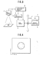
- an object to be detected is a circular body 1 shown in Fig. 3.
- An industrial television (ITV) camera 2 photographs the circular body or object in a predetermined field of view to send a video composite signal containing the brightness signal of the input picture image to a synchronous isolating circuit 3 and an A/D converter 4.
- the synchronous isolating circuit 3 operates to separate a synchronizing signal from the video composite signal.
- the synchronizing signal thus separated is used to designate an address of a random access memory array (RAM array) 5, while the A/D converter 4 converts the inputted video composite signal into a picture image data having 16 tones of brightness for writing the picture image data in the designated address.
- RAM array random access memory array
- Any desired picture image data can be read out by designating X and Y addresses of the RAM array 5.
- Memory means 6 stores the main program or the like for carrying out the method of this invention, and a central processing unit (CPU) 7 executes the processing of the picture image data stored in the RAM array in accordance with the content of the main program.
- CPU central processing unit
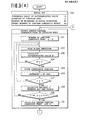
- the threshold value D of the differentiated value, the diameter L. of the circular body, the number of scannings Ns in the radial direction, and the present number No of the contour candidate point are set.
- the threshold value D is used to judge the contour candidate point at which the brightness of the picture image data varies rapidly.
- the number of scanning is selected to be 8 and the number of presets No is selected to be 6.
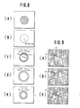
- the present picture image data (see Fig. 6a) in the RAM array 5 is searched for finding out the center position candidate point of the circular body.
- the search of the center position candidate point is made by differentiating in the X direction.
- the number n of the contour candidate points is set to zero, at step 102, tha.. present picture image is scanned in the X direction, and at step 103, the differentiated value D' of the picture image data is calculated.
- a judgment is made as to whether the differentiated value D' has exceeded the threshold value D or not.
- the coordinate position of D' is stored at step 105, and at step 106 n is incremented by one.
- a judgement is made as to whether n is equal to or larger than 2.
- the distance L' see Fig. 6b
- the center position candidate point C (X,Y) (see Fig. 6c) is calculated by utilizing the coordinate positions of the two points. It should be understood that the method of searching the center positions candidate point is not limited to the illustrated embodiment. For example, a method can be used wherein more than three contour candidate points are determined so as to calculate the center position candidate point based on a circle passing through these three points.
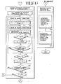
- the contour candidate point of the circular body is searched based on the center position candidate point of the circular body so as to check presence or absence of the contour line, that is, the circular body.
- the preset scanning directions are 8, that is 0 (+ X direction), ⁇ /4, ⁇ /2, 3 ⁇ /4, ⁇ , 5 ⁇ /4, 3 ⁇ /2 and 7 ⁇ /4 by taking the center position candidate point as the reference point (see Fig. 6d).
- the maximum differentiated value D max is set to zero at step 112. After that, at step 113, the scanning is made in either one of the eight radial directions and at step 114, the differentiated value D' of the picture image data is calculated. At step 115, a judgment is made as to whether the differentiated value D ' is larger than the maximum differentiated value D max or not. When the result is YES, at step 116, the differentiated value D' is changed for the maximum differentiated value D max so that in the scanning range, all maximum differentiated values are changed to the maximum differentiated values. At step 117, a judgment is made whether the scanning in the range has completed or not.
- step 118 a judgment is made as to whether the maximum differentiated value D has exceeded the threshold value D or not. max
- the number n of the contour candidate point is incremented by one.
- step 120 a judgement is made as to whether the contour candidate point presents or not in the eight scanning directions.
- the total number n of the contour candidate points is larger than the preset number No (in this example 6) of the contour candidate points, it is judged that the contour line of the circular body presents in the doughnut shaped region.
- the search of the center position candidate point of the circular body is performed again at step 121.
- step 122 when the presence of the contour line of the circular body is recognized, at step 122, an approximate circle is determined from n contour candidate points, and at step 123, the coordinates of the center of the circle and, if desired, its diameter are calculated (see Fig. 6e), thus finishing the processing of the picture image.
- the number Ns of scannings in the radial direction, the direction of scanning, and the preset number No establishing the threshold value are not limited to those described above.
- the continuity of the contour line is identified by the following method.
- Fig. 7 shows a flow chart indicative of the successive steps of the CPU 7 for identifying the continuity of the contour line.
- step 200 characterizing points of an object to be detected are extracted from the present picture image data (see Fig. 8a) stored in the RAM array 5.
- the object to be detected is assumed to be a circular body, as its characteristic point is detected --- the center position Po (Xo, Yo) of the circle (see Fig. 8b).
- the method of detecting the characteristic point is not limited to that described above and the characteristic point can be detected by differentiating in the X direction the picture image data stored in the RAM array 5 so as to detect characteristic point based on the two contour candidate positions the spacing therebetween becoming the maximum and the brightness changes abruptly, or by determining more than three contour candidate points and then calculating the center position of a circle passing the three points.
- X contour candidate points are presumed from the characteristic point Po and the radius of the circle.
- i is set to 1
- step 203 several picture elements Ci including the contour candidate point Pi, several picture elements Oi on the outside of the contour candidate point Pi, and several picture elements Ii on the inner side of the contour candidate point Pi are extracted (see Figs. 8c, 8d and 8e).
- the extraction should be made such that the three types of the picture image data would be arranged in substantially normal direction with respect to the loci of the contour candidate points.
- the direction of ⁇ of the normal is calculated by the following equation in accordance with the relative position between the characteristic point Po (Xo, Yo) and the contour candidate point Pi (Xi, Yi).
- Figs. 9a, 9b and 9c respectively show three picture elements Ci containing contour candidate point Pi, three picture elements Oi on the outside of the contour candidate point Pi and three picture elements Ii on the inside of the contour candidate point Pi.
- the mean values Ci, Oi and Ii of the brightness of the three types of the picture image data Ci, Oi and Ii are determined.
- a judgment is made as to whether i is equal to one or not and when the result of judgment is YES, at step 206, i is made to be 2 to execute again the foregoing steps.
- the program sequence is advanced to stop 207 where the differences Sc, So and S I between the mean values Ci, Oi and Ii and Ci-l, Oi-1 and Ii-1 which are obtained at adjacent contour candidate points are calculated according to the following equations.
- step 208 a check is made as to whether the differences Sc, So and S I thus calculated are included in the permissible range (from the lower limit T L to the upper limit T H ) preset as shown in Fig. 10.
- these differences are on the outside of the permissible range, it is judged that adjacent contour candidate points are discontinuous at step 211.
- adjacent contour candidate points are continuous. More particularly, as shown in Fig. 8, between C and D, there is a point at which the difference goes out of the permissible range, but where either one of the other differences lies in the permissible range, it is judged that adjacent contour candidate points are continuous.
- i is incremented by one for the purpose of checking whether the next adjacent contour candidate points are continuous or discontinuous, thus executing again above described steps.
- the object to be detected is not limited to a circular body.
- the method of this invention is applicable to judge whether a portion of the contour line is continuous or not as shown in Fig. 11, provided that the contour candidate points are presumed by certain experiments.
Landscapes
- Engineering & Computer Science (AREA)
- Computer Vision & Pattern Recognition (AREA)
- Physics & Mathematics (AREA)
- General Physics & Mathematics (AREA)
- Multimedia (AREA)
- Theoretical Computer Science (AREA)
- Image Analysis (AREA)
Applications Claiming Priority (4)
| Application Number | Priority Date | Filing Date | Title |
|---|---|---|---|
| JP4451/84 | 1984-01-13 | ||
| JP59004451A JPS60147886A (ja) | 1984-01-13 | 1984-01-13 | 輪郭線の連続性認識方法 |
| JP59026580A JPS60179881A (ja) | 1984-02-15 | 1984-02-15 | 輪郭線の認識方法 |
| JP26580/84 | 1984-02-15 |
Publications (3)
| Publication Number | Publication Date |
|---|---|
| EP0149457A2 true EP0149457A2 (fr) | 1985-07-24 |
| EP0149457A3 EP0149457A3 (en) | 1989-02-22 |
| EP0149457B1 EP0149457B1 (fr) | 1993-03-31 |
Family
ID=26338218
Family Applications (1)
| Application Number | Title | Priority Date | Filing Date |
|---|---|---|---|
| EP85100073A Expired - Lifetime EP0149457B1 (fr) | 1984-01-13 | 1985-01-04 | Méthode d'identification de lignes de contour |
Country Status (3)
| Country | Link |
|---|---|
| US (1) | US4644583A (fr) |
| EP (1) | EP0149457B1 (fr) |
| DE (1) | DE3587220T2 (fr) |
Cited By (13)
| Publication number | Priority date | Publication date | Assignee | Title |
|---|---|---|---|---|
| US4627096A (en) * | 1984-02-24 | 1986-12-02 | Consiglio Nazionale Delle Ricerche | Procedure and apparatus for the survey of the impression made on a specimen in measuring the hardness at penetration |
| WO1987003719A1 (fr) * | 1985-12-16 | 1987-06-18 | National Research Development Corporation | Appareil de controle |
| EP0225428A3 (en) * | 1985-11-30 | 1988-10-19 | Ant Nachrichtentechnik Gmbh | Method for the recognition of edge structures in a picture signal |
| EP0334230A3 (en) * | 1988-03-19 | 1990-11-14 | Fuji Photo Film Co., Ltd. | Method for detecting prospective contour points of an irradiation field |
| EP0316005A3 (fr) * | 1987-11-12 | 1991-03-27 | Kabushiki Kaisha Toshiba | Codeur de figures |
| EP0367952A3 (fr) * | 1988-10-31 | 1991-11-06 | International Business Machines Corporation | Système pour détecter et analyser des objets arrondis |
| EP0287113A3 (fr) * | 1987-04-16 | 1992-04-01 | Fuji Photo Film Co., Ltd. | Procédé de reconnaissance de champ d'irradiation |
| FR2720536A1 (fr) * | 1990-09-27 | 1995-12-01 | Loral Aerospace Corp | Procédé pour éliminer le fond parasite d'une image sur la base d'une corrélation. |
| CN102063016A (zh) * | 2009-11-16 | 2011-05-18 | 优志旺电机株式会社 | 对准标记的检测方法 |
| DE102010020330A1 (de) * | 2010-05-14 | 2011-11-17 | Conti Temic Microelectronic Gmbh | Verfahren zur Erkennung von Verkehrszeichen |
| US9418303B2 (en) | 2009-10-01 | 2016-08-16 | Conti Temic Microelectronic Gmbh | Method for traffic sign recognition |
| US9436879B2 (en) | 2011-08-04 | 2016-09-06 | Conti Temic Microelectronic Gmbh | Method for recognizing traffic signs |
| US9697430B2 (en) | 2013-10-01 | 2017-07-04 | Conti Temic Microelectronic Gmbh | Method and apparatus for identifying road signs |
Families Citing this family (45)
| Publication number | Priority date | Publication date | Assignee | Title |
|---|---|---|---|---|
| GB2175396B (en) * | 1985-05-22 | 1989-06-28 | Filler Protection Developments | Apparatus for examining objects |
| SE448124B (sv) * | 1985-05-23 | 1987-01-19 | Context Vision Ab | Anordning for detektering av variationsgraden av en egenskap i ett omrade av en i diskreta bildelement uppdelad bild |
| SE448125B (sv) * | 1985-05-23 | 1987-01-19 | Context Vision Ab | Anordning for bestemning av graden av konstans hos en egenskap for ett omrade i en i diskreta bildelement uppdelad bild |
| SE448126B (sv) * | 1985-05-23 | 1987-01-19 | Context Vision Ab | Anordning for detektering av sprangartade forendringar av en egenskap inom ett omrade av en i diskreta bildelement uppdelad bild |
| KR900007548B1 (ko) * | 1985-10-04 | 1990-10-15 | 다이닛뽕스쿠링세이소오 가부시키가이샤 | 패턴 마스킹 방법 및 그 장치 |
| JPS62103508A (ja) * | 1985-10-31 | 1987-05-14 | Hajime Sangyo Kk | 物体の外形検査方法及び装置 |
| JPS62209305A (ja) * | 1986-03-10 | 1987-09-14 | Fujitsu Ltd | 寸法良否判定方法 |
| JPS62209304A (ja) * | 1986-03-10 | 1987-09-14 | Fujitsu Ltd | 寸法測定方法 |
| US5214718A (en) * | 1986-10-06 | 1993-05-25 | Ampex Systems Corporation | Scan-in polygonal extraction of video images |
| US4759074A (en) * | 1986-10-28 | 1988-07-19 | General Motors Corporation | Method for automatically inspecting parts utilizing machine vision and system utilizing same |
| US4933865A (en) * | 1986-12-20 | 1990-06-12 | Fujitsu Limited | Apparatus for recognition of drawn shapes or view types for automatic drawing input in CAD system |
| US4825263A (en) * | 1987-06-02 | 1989-04-25 | University Of Medicine & Dentistry Of New Jersey | Optical method and apparatus for determining three-dimensional changes in facial contours |
| US4961425A (en) * | 1987-08-14 | 1990-10-09 | Massachusetts Institute Of Technology | Morphometric analysis of anatomical tomographic data |
| US4882622A (en) * | 1987-09-18 | 1989-11-21 | Toppan Printing Co., Ltd. | Silhouette cutting apparatus |
| US4992663A (en) * | 1988-03-19 | 1991-02-12 | Fuji Photo Film Co., Ltd. | Method of judging the correctness or incorrectness of a prospective contour point of an irradiation field |
| US4901361A (en) * | 1988-05-27 | 1990-02-13 | The United States Of America As Represented By The Secretary Of The Air Force | Automated spall panel analyzer |
| GB8906587D0 (en) * | 1989-03-22 | 1989-05-04 | Philips Electronic Associated | Region/texture coding systems |
| JPH083405B2 (ja) * | 1989-06-30 | 1996-01-17 | 松下電器産業株式会社 | リード位置認識装置 |
| US5054094A (en) * | 1990-05-07 | 1991-10-01 | Eastman Kodak Company | Rotationally impervious feature extraction for optical character recognition |
| JP2528376B2 (ja) * | 1990-06-28 | 1996-08-28 | 大日本スクリーン製造株式会社 | 画像の輪郭修正方法 |
| JP2982150B2 (ja) * | 1990-08-28 | 1999-11-22 | キヤノン株式会社 | 文字パターン処理方法及び装置 |
| US5287293A (en) * | 1990-12-31 | 1994-02-15 | Industrial Technology Research Institute | Method and apparatus for inspecting the contours of a gear |
| JPH04237383A (ja) * | 1991-01-22 | 1992-08-25 | Matsushita Electric Ind Co Ltd | 二次元画像処理における円弧近似方法 |
| US5134661A (en) * | 1991-03-04 | 1992-07-28 | Reinsch Roger A | Method of capture and analysis of digitized image data |
| JP2639518B2 (ja) * | 1991-10-30 | 1997-08-13 | 大日本スクリーン製造株式会社 | 画像処理方法 |
| US5590220A (en) * | 1992-08-12 | 1996-12-31 | International Business Machines Corporation | Bending point extraction method for optical character recognition system |
| US5339367A (en) * | 1992-12-02 | 1994-08-16 | National Research Council Of Canada | Identifying curves within a scanned image |
| JP2919284B2 (ja) * | 1994-02-23 | 1999-07-12 | 松下電工株式会社 | 物体認識方法 |
| US6178262B1 (en) * | 1994-03-11 | 2001-01-23 | Cognex Corporation | Circle location |
| US6021222A (en) * | 1994-08-16 | 2000-02-01 | Ricoh Co., Ltd. | System and method for the detection of a circle image for pattern recognition |
| US6084986A (en) * | 1995-02-13 | 2000-07-04 | Eastman Kodak Company | System and method for finding the center of approximately circular patterns in images |
| JPH09138471A (ja) * | 1995-09-13 | 1997-05-27 | Fuji Photo Film Co Ltd | 特定形状領域の抽出方法、特定領域の抽出方法及び複写条件決定方法 |
| FR2743415B1 (fr) * | 1996-01-09 | 1998-02-13 | Service Central Des Laboratoir | Procede de comparaison de projectiles et dispositif |
| FR2743416B1 (fr) * | 1996-01-09 | 1998-02-13 | Service Central Des Laboratoir | Procede de comparaison de douilles projectiles et dispositif |
| US6714679B1 (en) | 1998-02-05 | 2004-03-30 | Cognex Corporation | Boundary analyzer |
| US6697535B1 (en) | 1999-04-30 | 2004-02-24 | Cognex Technology And Investment Corporation | Method for refining a parameter of a contour in an image |
| US6901171B1 (en) | 1999-04-30 | 2005-05-31 | Cognex Technology And Investment Corporation | Methods and apparatuses for refining groupings of edge points that represent a contour in an image |
| JP2001119610A (ja) * | 1999-08-10 | 2001-04-27 | Alps Electric Co Ltd | 輪郭検出回路及び画像表示装置 |
| US7474787B2 (en) * | 1999-12-28 | 2009-01-06 | Minolta Co., Ltd. | Apparatus and method of detecting specified pattern |
| TWI254234B (en) * | 2004-12-24 | 2006-05-01 | Hon Hai Prec Ind Co Ltd | System and method for auto-judging geometric shape trend of a set of dots on an image |
| DE102005023376A1 (de) * | 2005-05-17 | 2006-11-23 | Carl Zeiss Industrielle Messtechnik Gmbh | Verfahren und Vorrichtung zum Bestimmen von Materialgrenzen eines Prüfobjektes |
| TWI320914B (en) * | 2006-07-28 | 2010-02-21 | Via Tech Inc | Weight-adjusted apparatus and method thereof |
| US10896327B1 (en) * | 2013-03-15 | 2021-01-19 | Spatial Cam Llc | Device with a camera for locating hidden object |
| JP2016123407A (ja) | 2014-12-26 | 2016-07-11 | 富士通株式会社 | 画像処理装置、画像処理方法および画像処理プログラム |
| US20170337689A1 (en) * | 2016-05-20 | 2017-11-23 | Yung-Hui Li | Method for validating segmentation of objects with arbitrary shapes |
Family Cites Families (5)
| Publication number | Priority date | Publication date | Assignee | Title |
|---|---|---|---|---|
| US4017721A (en) * | 1974-05-16 | 1977-04-12 | The Bendix Corporation | Method and apparatus for determining the position of a body |
| JPS5218136A (en) * | 1975-08-01 | 1977-02-10 | Hitachi Ltd | Signal processing unit |
| US4115761A (en) * | 1976-02-13 | 1978-09-19 | Hitachi, Ltd. | Method and device for recognizing a specific pattern |
| US4228432A (en) * | 1979-08-28 | 1980-10-14 | The United States Of America As Represented By The Secretary Of The Navy | Raster scan generator for plan view display |
| JPS5926064B2 (ja) * | 1979-09-10 | 1984-06-23 | 工業技術院長 | 輪郭画像の特徴抽出装置 |
-
1985
- 1985-01-04 EP EP85100073A patent/EP0149457B1/fr not_active Expired - Lifetime
- 1985-01-04 DE DE8585100073T patent/DE3587220T2/de not_active Expired - Fee Related
- 1985-01-14 US US06/691,016 patent/US4644583A/en not_active Expired - Fee Related
Cited By (15)
| Publication number | Priority date | Publication date | Assignee | Title |
|---|---|---|---|---|
| US4627096A (en) * | 1984-02-24 | 1986-12-02 | Consiglio Nazionale Delle Ricerche | Procedure and apparatus for the survey of the impression made on a specimen in measuring the hardness at penetration |
| EP0225428A3 (en) * | 1985-11-30 | 1988-10-19 | Ant Nachrichtentechnik Gmbh | Method for the recognition of edge structures in a picture signal |
| US4896364A (en) * | 1985-11-30 | 1990-01-23 | Ant Nachrichtentechnik Gmbh | Method of detecting boundary structures in a video signal |
| WO1987003719A1 (fr) * | 1985-12-16 | 1987-06-18 | National Research Development Corporation | Appareil de controle |
| EP0287113A3 (fr) * | 1987-04-16 | 1992-04-01 | Fuji Photo Film Co., Ltd. | Procédé de reconnaissance de champ d'irradiation |
| EP0316005A3 (fr) * | 1987-11-12 | 1991-03-27 | Kabushiki Kaisha Toshiba | Codeur de figures |
| EP0334230A3 (en) * | 1988-03-19 | 1990-11-14 | Fuji Photo Film Co., Ltd. | Method for detecting prospective contour points of an irradiation field |
| EP0367952A3 (fr) * | 1988-10-31 | 1991-11-06 | International Business Machines Corporation | Système pour détecter et analyser des objets arrondis |
| FR2720536A1 (fr) * | 1990-09-27 | 1995-12-01 | Loral Aerospace Corp | Procédé pour éliminer le fond parasite d'une image sur la base d'une corrélation. |
| US9418303B2 (en) | 2009-10-01 | 2016-08-16 | Conti Temic Microelectronic Gmbh | Method for traffic sign recognition |
| CN102063016A (zh) * | 2009-11-16 | 2011-05-18 | 优志旺电机株式会社 | 对准标记的检测方法 |
| DE102010020330A1 (de) * | 2010-05-14 | 2011-11-17 | Conti Temic Microelectronic Gmbh | Verfahren zur Erkennung von Verkehrszeichen |
| US8953842B2 (en) | 2010-05-14 | 2015-02-10 | Conti Temic Microelectronic Gmbh | Method for road sign recognition |
| US9436879B2 (en) | 2011-08-04 | 2016-09-06 | Conti Temic Microelectronic Gmbh | Method for recognizing traffic signs |
| US9697430B2 (en) | 2013-10-01 | 2017-07-04 | Conti Temic Microelectronic Gmbh | Method and apparatus for identifying road signs |
Also Published As
| Publication number | Publication date |
|---|---|
| DE3587220D1 (de) | 1993-05-06 |
| EP0149457A3 (en) | 1989-02-22 |
| EP0149457B1 (fr) | 1993-03-31 |
| US4644583A (en) | 1987-02-17 |
| DE3587220T2 (de) | 1993-07-08 |
Similar Documents
| Publication | Publication Date | Title |
|---|---|---|
| EP0149457A2 (fr) | Méthode d'identification de lignes de contour | |
| US5629989A (en) | Image line-segment extracting apparatus | |
| US4941192A (en) | Method and apparatus for recognizing pattern of gray level image | |
| Reid et al. | A semi-automated methodology for discontinuity trace detection in digital images of rock mass exposures | |
| US20030063782A1 (en) | Method and apparatus to reduce false minutiae in a binary fingerprint image | |
| EP0124789A2 (fr) | Méthode pour identifier des objets | |
| US4876729A (en) | Method of identifying objects | |
| US7072496B2 (en) | Slap print segmentation system and method | |
| US5065439A (en) | Pattern recognition apparatus | |
| CN112801090A (zh) | 文字区域检测方法及装置 | |
| JPH0432428B2 (fr) | ||
| AU2015318811B2 (en) | Arc detection system and method | |
| JP2000003436A (ja) | Isar画像識別装置およびisar画像識別方法 | |
| JP2833313B2 (ja) | 指紋特徴点の真偽判定装置 | |
| JPH08304302A (ja) | 検査対象物の表面傷検出方法 | |
| JP3281469B2 (ja) | 文書画像の傾き検出方法および装置 | |
| JP3651037B2 (ja) | 線分検出方法およびその装置 | |
| KR19990005319A (ko) | 영상 데이터베이스 검색방법 | |
| JPH0217832B2 (fr) | ||
| EP0297627B1 (fr) | Méthode pour identifier des objets | |
| JPH0797410B2 (ja) | 画像処理方法 | |
| JP3417621B2 (ja) | 特定画像検出方法及び特定画像検出装置 | |
| JP3087788B2 (ja) | 部品の位置検出方法及び装置 | |
| JP2959017B2 (ja) | 円形画像判別方法 | |
| JPH09282453A (ja) | 位置認識方法 |
Legal Events
| Date | Code | Title | Description |
|---|---|---|---|
| PUAI | Public reference made under article 153(3) epc to a published international application that has entered the european phase |
Free format text: ORIGINAL CODE: 0009012 |
|
| AK | Designated contracting states |
Designated state(s): DE FR GB SE |
|
| PUAL | Search report despatched |
Free format text: ORIGINAL CODE: 0009013 |
|
| AK | Designated contracting states |
Kind code of ref document: A3 Designated state(s): DE FR GB SE |
|
| 17P | Request for examination filed |
Effective date: 19890403 |
|
| 17Q | First examination report despatched |
Effective date: 19910516 |
|
| GRAA | (expected) grant |
Free format text: ORIGINAL CODE: 0009210 |
|
| AK | Designated contracting states |
Kind code of ref document: B1 Designated state(s): DE FR GB SE |
|
| REF | Corresponds to: |
Ref document number: 3587220 Country of ref document: DE Date of ref document: 19930506 |
|
| ET | Fr: translation filed | ||
| PGFP | Annual fee paid to national office [announced via postgrant information from national office to epo] |
Ref country code: DE Payment date: 19940110 Year of fee payment: 10 |
|
| PGFP | Annual fee paid to national office [announced via postgrant information from national office to epo] |
Ref country code: FR Payment date: 19940111 Year of fee payment: 10 |
|
| PGFP | Annual fee paid to national office [announced via postgrant information from national office to epo] |
Ref country code: SE Payment date: 19940117 Year of fee payment: 10 |
|
| PLBE | No opposition filed within time limit |
Free format text: ORIGINAL CODE: 0009261 |
|
| STAA | Information on the status of an ep patent application or granted ep patent |
Free format text: STATUS: NO OPPOSITION FILED WITHIN TIME LIMIT |
|
| 26N | No opposition filed | ||
| PGFP | Annual fee paid to national office [announced via postgrant information from national office to epo] |
Ref country code: GB Payment date: 19941229 Year of fee payment: 11 |
|
| PG25 | Lapsed in a contracting state [announced via postgrant information from national office to epo] |
Ref country code: SE Effective date: 19950105 |
|
| EAL | Se: european patent in force in sweden |
Ref document number: 85100073.7 |
|
| PG25 | Lapsed in a contracting state [announced via postgrant information from national office to epo] |
Ref country code: FR Effective date: 19950929 |
|
| PG25 | Lapsed in a contracting state [announced via postgrant information from national office to epo] |
Ref country code: DE Effective date: 19951003 |
|
| EUG | Se: european patent has lapsed |
Ref document number: 85100073.7 |
|
| REG | Reference to a national code |
Ref country code: FR Ref legal event code: ST |
|
| PG25 | Lapsed in a contracting state [announced via postgrant information from national office to epo] |
Ref country code: GB Effective date: 19960104 |
|
| GBPC | Gb: european patent ceased through non-payment of renewal fee |
Effective date: 19960104 |