EP0149492A2 - Charnière pour porte de véhicule automobile - Google Patents
Charnière pour porte de véhicule automobile Download PDFInfo
- Publication number
- EP0149492A2 EP0149492A2 EP85100416A EP85100416A EP0149492A2 EP 0149492 A2 EP0149492 A2 EP 0149492A2 EP 85100416 A EP85100416 A EP 85100416A EP 85100416 A EP85100416 A EP 85100416A EP 0149492 A2 EP0149492 A2 EP 0149492A2
- Authority
- EP
- European Patent Office
- Prior art keywords
- bolt
- door
- frame part
- door hinge
- hinge according
- Prior art date
- Legal status (The legal status is an assumption and is not a legal conclusion. Google has not performed a legal analysis and makes no representation as to the accuracy of the status listed.)
- Withdrawn
Links
Images
Classifications
-
- E—FIXED CONSTRUCTIONS
- E05—LOCKS; KEYS; WINDOW OR DOOR FITTINGS; SAFES
- E05D—HINGES OR SUSPENSION DEVICES FOR DOORS, WINDOWS OR WINGS
- E05D7/00—Hinges or pivots of special construction
- E05D7/10—Hinges or pivots of special construction to allow easy separation or connection of the parts at the hinge axis
- E05D7/1005—Hinges or pivots of special construction to allow easy separation or connection of the parts at the hinge axis by axially moving free pins, balls or sockets
-
- E—FIXED CONSTRUCTIONS
- E05—LOCKS; KEYS; WINDOW OR DOOR FITTINGS; SAFES
- E05D—HINGES OR SUSPENSION DEVICES FOR DOORS, WINDOWS OR WINGS
- E05D5/00—Construction of single parts, e.g. the parts for attachment
- E05D5/10—Pins, sockets or sleeves; Removable pins
-
- E—FIXED CONSTRUCTIONS
- E05—LOCKS; KEYS; WINDOW OR DOOR FITTINGS; SAFES
- E05D—HINGES OR SUSPENSION DEVICES FOR DOORS, WINDOWS OR WINGS
- E05D3/00—Hinges with pins
- E05D3/02—Hinges with pins with one pin
- E05D2003/025—Hinges with pins with one pin having three knuckles
- E05D2003/027—Hinges with pins with one pin having three knuckles the end knuckles being mutually connected
-
- E—FIXED CONSTRUCTIONS
- E05—LOCKS; KEYS; WINDOW OR DOOR FITTINGS; SAFES
- E05D—HINGES OR SUSPENSION DEVICES FOR DOORS, WINDOWS OR WINGS
- E05D5/00—Construction of single parts, e.g. the parts for attachment
- E05D5/10—Pins, sockets or sleeves; Removable pins
- E05D2005/102—Pins
- E05D2005/106—Pins with non-cylindrical portions
-
- E—FIXED CONSTRUCTIONS
- E05—LOCKS; KEYS; WINDOW OR DOOR FITTINGS; SAFES
- E05D—HINGES OR SUSPENSION DEVICES FOR DOORS, WINDOWS OR WINGS
- E05D7/00—Hinges or pivots of special construction
- E05D7/10—Hinges or pivots of special construction to allow easy separation or connection of the parts at the hinge axis
- E05D2007/1094—Guiding devices therefor
-
- E—FIXED CONSTRUCTIONS
- E05—LOCKS; KEYS; WINDOW OR DOOR FITTINGS; SAFES
- E05D—HINGES OR SUSPENSION DEVICES FOR DOORS, WINDOWS OR WINGS
- E05D5/00—Construction of single parts, e.g. the parts for attachment
- E05D5/10—Pins, sockets or sleeves; Removable pins
- E05D5/12—Securing pins in sockets, movably or not
- E05D5/127—Securing pins in sockets, movably or not by forcing the pin into the socket
-
- E—FIXED CONSTRUCTIONS
- E05—LOCKS; KEYS; WINDOW OR DOOR FITTINGS; SAFES
- E05D—HINGES OR SUSPENSION DEVICES FOR DOORS, WINDOWS OR WINGS
- E05D7/00—Hinges or pivots of special construction
- E05D7/10—Hinges or pivots of special construction to allow easy separation or connection of the parts at the hinge axis
- E05D7/1083—Hinges or pivots of special construction to allow easy separation or connection of the parts at the hinge axis facilitating simultaneous assembly of a plurality of hinges, e.g. for mounting heavy wings
-
- E—FIXED CONSTRUCTIONS
- E05—LOCKS; KEYS; WINDOW OR DOOR FITTINGS; SAFES
- E05Y—INDEXING SCHEME ASSOCIATED WITH SUBCLASSES E05D AND E05F, RELATING TO CONSTRUCTION ELEMENTS, ELECTRIC CONTROL, POWER SUPPLY, POWER SIGNAL OR TRANSMISSION, USER INTERFACES, MOUNTING OR COUPLING, DETAILS, ACCESSORIES, AUXILIARY OPERATIONS NOT OTHERWISE PROVIDED FOR, APPLICATION THEREOF
- E05Y2900/00—Application of doors, windows, wings or fittings thereof
- E05Y2900/50—Application of doors, windows, wings or fittings thereof for vehicles
- E05Y2900/53—Type of wing
- E05Y2900/531—Doors
Definitions
- the invention relates to a door hinge for a motor vehicle, which consists of a frame part, a door part enclosed by the eyes of the frame part and a bolt for the articulated connection of both parts, in which at least one dry bearing bush is arranged between the door part and the bolt.
- the unlocked vehicle doors take up so much space in the final assembly phase that many automobile manufacturers have begun to unhinge the doors during this phase, to complete them separately and later on again to unite the rest of the vehicle.
- the previous attachment of the doors is required for painting in the immersion bath, for example, which are then already in a state aligned with the rest of the body. During the temporary dismantling of the Doors must not lose the adjustment they have already found.
- the temporary disassembly must be effected by driving out or pulling out the hinge pin, in particular the later re-threading of the door part between the eyes of the frame part being difficult very easily damaged to form a bearing layer between the door part and the respective eyes of the frame part, the actual bearing layer of these two- or three-layer bearing bushes, which can be designed to be inherently stiff or in need of support, is very soft, so that a rough contact, for example, with the outer edge of a partial frame eye is sufficient to make the bearing bush unusable.
- the invention proposes that an articulated sleeve is inserted between each dry bearing bush and the bolt, which is fixed in a rotationally fixed manner to the bolt anchored in the frame part.
- the rotary movement takes place in the hinge between the respective joint sleeve and the dry bearing bush.
- This pair of bearings is, however, preassembled to a certain extent in the door part, so that when the door is dismantled, the components involved in the storage are not separated from one another.
- the bolt used for the assembly of the door hinge according to the invention thus only serves to connect the Joint sleeves to the eyes of the frame part and to maintain a coaxial position of these components to ensure trouble-free function.
- the joint sleeve is preferably designed as a collar sleeve. Between the respective collar of an articulated sleeve and the door part, two end faces are formed that move against one another during a hinge movement, between which a collar molded onto the dry bearing bush acts as a spacer and lubricant. In this way, a dry lubricated bearing is also available in the axial direction of the bolt.
- a multi-layer bushing is preferably used as the material for the dry bearing bushing, in which an impregnated bronze intermediate layer and the actual bearing material in the form of a leaded PTFE is applied to a metallic backing, which preferably consists of steel.
- Such multi-layer bushings are commercially available as DU bushings.
- the hinge pin is driven into the hinge, e.g. Knurling anchoring in one or both eyes of the frame part and for fastening the joint sleeves to the bolt.
- the bolt is pulled out of the hinge and the door part is removed from the frame part;
- the relatively tight fit of the bushings and sleeves ensures that the cohesion of the completed door part is retained even when the door part is removed from the frame part.
- each dry bearing bush is designed as a multi-layer bush with a metallic back and a leaded PTFE bearing layer, that the bolt has the metallic back facing, and that each dry bearing bush is rotatably attached to the bolt anchored in the frame part.
- each multi-layer bushing is assigned to the articulated bolt anchored in the frame part and thus does not itself perform any movement during a hinge movement.
- the metallic back of the known multi-layer bushes is not particularly strong, but it is sufficient to make it non-rotatable To be able to establish a connection, for example with the aid of knurling with the bolt.
- the sliding movement then takes place between the outer bearing material of the multilayer bush and the inner surface of the door part.
- the multi-layer bushings available with a collar can be used in the simplest way to form a corresponding axial bearing in this proposal of the invention, expediently using two collar bushings, one from each side being inserted into the hole in the door part.
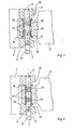
- the hinge shown in Figure 1 consists essentially of a frame part 1, a door part 2 and a bolt 3 ' ; that indirectly creates an articulated connection between the two parts. Both parts 1 and 2 are provided in the usual way with screw holes (not shown) so that they can be screwed to the door jamb on the one hand and to the door of a motor vehicle on the other hand with the aid of two bolts or vice versa. Underneath a head 4 on the bolt 3 there is a notch 5 on which tools can engage if the hinge is intended to be dismantled from the situation of final assembly shown.
- the actual storage of the hinge is between two articulated sleeves 9 formed as collar sleeves on the one hand and two multilayer sleeves 13 likewise formed as collar sleeves on the other hand, each of which is inserted with its cylindrical shaft into the bore in the door part 2.
- the tolerances are chosen so that the collar sleeves 9, supported by knurls 11, are stuck on the bolt 3, while the multi-layer bushings 13 are immovably driven into the door part 2.
- the door part completed in this way can be pushed with the desired operating play between the eyes of the frame part 1, whereby a chamfer 10 on the collar sleeves 9 and bevels 15 on the frame part 1 facilitate threading. Because of these bevels and chamfers, a door can be hung in with the aid of a device that can only thread in a relatively large tolerance range.
- the bolt 3 can be inserted by hand or also with the aid of a device, the last misalignment being eliminated by rounding or strong chamfering at the front end of the bolt 3.
- the bolt 3 carries in the area of the lower eye of the frame part 1 a strong knurling 6, which ensures its anchoring within the frame part, both in the axial direction and as a safeguard against twisting.
- Similar knurls 11 are located at the level of the hinge sleeves 9. These knurls 11 are weaker overall, so that although they prevent the hinge sleeve 9 from rotating relative to the bolt 3, they still allow the bolt 3 to be driven into the hinge with sufficient ease.
- FIG. 2 shows a further embodiment of the invention, in which the frame part 1 and Bolts 3 are identical to the embodiment of Figure 1; the actual design of the joint and in this context the design of the door part 2 is different.
- a collar bushing in the form of a multi-layer bushing 17 is pushed into the bore of the door part 2 from each side and carries the bearing material on its outside, that is, it forms the bearing pairing with the inner surface of the bore in the door part 2.
- the steel back of these multilayer bushes 17 faces the bolt 3, the steel back facing the eyes of the frame part 1 in the region of the respective collar.
- Knurls 11 are also provided to fix the multi-layer bushings 17 with respect to the bolt 3 against rotation, which in turn are not as strong as the knurling 6 used for anchoring in the frame part 1.
- bevels 18 are arranged on the front side of the door part 2, the ratios being able to be chosen such that when the bevel 18 touches one of the bevels 15 the frame part 1 of the collar of the associated multilayer bushing 17 has not yet come into contact with the bevels 15. In this way, the multilayer bushes 17 are protected as much as possible, which are somewhat protected by their steel backing, but are still vulnerable to strong impacts.
- the bolt 3 is preferably made of a corrosion-resistant steel with an austenitic or ferritic structure. This material has proven to be a particularly good friction partner for the plastic PTFE, so that with this material pairing a high level of reliability without extending the operating cycle over a very long time Period is reached.
Landscapes
- Engineering & Computer Science (AREA)
- Mechanical Engineering (AREA)
- Hinges (AREA)
- Power-Operated Mechanisms For Wings (AREA)
Applications Claiming Priority (2)
| Application Number | Priority Date | Filing Date | Title |
|---|---|---|---|
| DE19843401245 DE3401245A1 (de) | 1984-01-16 | 1984-01-16 | Tuerscharnier fuer ein kraftfahrzeug |
| DE3401245 | 1984-01-16 |
Publications (2)
| Publication Number | Publication Date |
|---|---|
| EP0149492A2 true EP0149492A2 (fr) | 1985-07-24 |
| EP0149492A3 EP0149492A3 (fr) | 1985-08-14 |
Family
ID=6225039
Family Applications (1)
| Application Number | Title | Priority Date | Filing Date |
|---|---|---|---|
| EP85100416A Withdrawn EP0149492A3 (fr) | 1984-01-16 | 1985-01-16 | Charnière pour porte de véhicule automobile |
Country Status (2)
| Country | Link |
|---|---|
| EP (1) | EP0149492A3 (fr) |
| DE (1) | DE3401245A1 (fr) |
Cited By (13)
| Publication number | Priority date | Publication date | Assignee | Title |
|---|---|---|---|---|
| EP0226046A1 (fr) * | 1985-12-07 | 1987-06-24 | Carl Sülberg GmbH & Co. | Charnière |
| DE3723415A1 (de) * | 1986-07-15 | 1988-02-18 | Honda Motor Co Ltd | Verfahren und mechanismus zum anbauen und abbauen einer automobiltuer an einen bzw. von einem automobilkoerper |
| EP0255879A3 (en) * | 1986-08-07 | 1988-05-04 | Lunke & Sohn Gmbh | Vehicle door hinge with a door check |
| FR2606822A1 (fr) * | 1986-11-14 | 1988-05-20 | Comaci Sa | Charniere demontable a axe visse avec butee d'ouverture |
| EP0290107A1 (fr) * | 1987-05-07 | 1988-11-09 | Rockwool Lapinus B.V. | Dispositif de levage pour éléments de construction articulés par une charnière et une charnière et l'élément de levage correspondant |
| EP0508806A1 (fr) * | 1991-04-12 | 1992-10-14 | ITW Limited | Charnière de porte |
| EP0828050A1 (fr) * | 1996-09-06 | 1998-03-11 | Renault | Charnière de porte, notamment pour véhicule automobile |
| US6808333B2 (en) * | 2002-10-30 | 2004-10-26 | Cnh Canada, Ltd | Pivot pin assembly |
| ES2245233A1 (es) * | 2004-05-31 | 2005-12-16 | Flexngate Automotive Iberica, S.A. | Bisagra de puerta para un vehiculo. |
| US7441308B1 (en) * | 2005-06-23 | 2008-10-28 | The United States Of America As Represented By The Secretary Of The Navy | Watertight door hinge support |
| US8567014B1 (en) * | 2012-07-06 | 2013-10-29 | San Kong Enterprise Co., Ltd. | Foldable handle |
| WO2018137907A1 (fr) * | 2017-01-24 | 2018-08-02 | Siemens Aktiengesellschaft | Palier rotatif pour battant latéral d'un véhicule |
| US10184280B2 (en) * | 2016-06-02 | 2019-01-22 | Flex-N-Gate Advanced Product Development, Llc. | Automotive door hinge |
Families Citing this family (6)
| Publication number | Priority date | Publication date | Assignee | Title |
|---|---|---|---|---|
| FR2604475A1 (fr) * | 1986-09-30 | 1988-04-01 | Ferco Interna Usine Ferrures B | Paumelle a blocage axial de la broche pour porte ou fenetre |
| DE19832025B4 (de) * | 1998-03-09 | 2005-08-25 | Schüring GmbH & Co. Fenstertechnologie KG | Höhenverstellbares Gelenkband |
| US6173475B1 (en) * | 1999-02-22 | 2001-01-16 | Powerbrace Corporation | Hinge assembly |
| DE10028694B4 (de) * | 2000-06-09 | 2007-12-06 | Bayerische Motoren Werke Ag | Scharnier, insbesondere für eine Fahrzeugklappe |
| TR201817491A2 (tr) * | 2018-11-20 | 2020-06-22 | Tofas Tuerk Otomobil Fabrikasi Anonim Sirketi | Bagaj kapaği i̇çi̇n bi̇r menteşe |
| DE102020108115B3 (de) * | 2020-03-24 | 2020-12-17 | Simonswerk Gmbh | Scharnieranordnung, Türband und Verfahren zu deren Herstellung |
Family Cites Families (5)
| Publication number | Priority date | Publication date | Assignee | Title |
|---|---|---|---|---|
| DE1425066B2 (de) * | 1963-05-18 | 1969-11-27 | Melton, James Otho, Norman; Wilkinson, Thomas Benton; Oklahoma City; OkIa. (V.St.A.) | Gelenkzapfenlager |
| DE2052513C2 (de) * | 1970-10-26 | 1984-05-24 | Ed. Scharwächter GmbH & Co KG, 5630 Remscheid | Scharnierstiftlagerung an einem Scharnier mit wartungsfrei gelagertem Scharnierstift und Verfahren zur Herstellung einer Scharnierstiftlagerung |
| DE2159801B2 (de) * | 1971-12-02 | 1977-09-29 | Karl Schmidt Gmbh, 7107 Neckarsulm | Wartungsfreies scharnier |
| DE2851234A1 (de) * | 1978-11-27 | 1980-06-12 | Scharwaechter Gmbh Co Kg | Fluegelscharnier mit wartungsfrei gelagertem scharnierstift |
| DE3338560A1 (de) * | 1983-09-19 | 1985-04-18 | Ed. Scharwächter GmbH & Co KG, 5630 Remscheid | Scharnier fuer kraftwagentueren |
-
1984
- 1984-01-16 DE DE19843401245 patent/DE3401245A1/de active Granted
-
1985
- 1985-01-16 EP EP85100416A patent/EP0149492A3/fr not_active Withdrawn
Cited By (20)
| Publication number | Priority date | Publication date | Assignee | Title |
|---|---|---|---|---|
| EP0226046A1 (fr) * | 1985-12-07 | 1987-06-24 | Carl Sülberg GmbH & Co. | Charnière |
| DE3723415A1 (de) * | 1986-07-15 | 1988-02-18 | Honda Motor Co Ltd | Verfahren und mechanismus zum anbauen und abbauen einer automobiltuer an einen bzw. von einem automobilkoerper |
| GB2193931A (en) * | 1986-07-15 | 1988-02-24 | Honda Motor Co Ltd | Method of and mechanism for attaching and detaching automobile door |
| US4860424A (en) * | 1986-07-15 | 1989-08-29 | Honda Giken Kogyo Kabushiki Kaisha | Method of and mechanism for attaching an automobile door |
| GB2193931B (en) * | 1986-07-15 | 1991-03-13 | Honda Motor Co Ltd | Method of and mechanism for attaching automobile door |
| US5033163A (en) * | 1986-07-15 | 1991-07-23 | Honda Giken Kogyo Kabushiki Kaisha | Mechanism for attaching an automobile door |
| EP0255879A3 (en) * | 1986-08-07 | 1988-05-04 | Lunke & Sohn Gmbh | Vehicle door hinge with a door check |
| FR2606822A1 (fr) * | 1986-11-14 | 1988-05-20 | Comaci Sa | Charniere demontable a axe visse avec butee d'ouverture |
| EP0290107A1 (fr) * | 1987-05-07 | 1988-11-09 | Rockwool Lapinus B.V. | Dispositif de levage pour éléments de construction articulés par une charnière et une charnière et l'élément de levage correspondant |
| EP0508806A1 (fr) * | 1991-04-12 | 1992-10-14 | ITW Limited | Charnière de porte |
| EP0828050A1 (fr) * | 1996-09-06 | 1998-03-11 | Renault | Charnière de porte, notamment pour véhicule automobile |
| FR2753226A1 (fr) * | 1996-09-06 | 1998-03-13 | Renault | Charniere de porte, notamment pour vehicule automobile |
| US6808333B2 (en) * | 2002-10-30 | 2004-10-26 | Cnh Canada, Ltd | Pivot pin assembly |
| ES2245233A1 (es) * | 2004-05-31 | 2005-12-16 | Flexngate Automotive Iberica, S.A. | Bisagra de puerta para un vehiculo. |
| ES2245233B1 (es) * | 2004-05-31 | 2007-02-16 | Flexngate Automotive Iberica, S.A. | Bisagra de puerta para un vehiculo. |
| US7441308B1 (en) * | 2005-06-23 | 2008-10-28 | The United States Of America As Represented By The Secretary Of The Navy | Watertight door hinge support |
| US8567014B1 (en) * | 2012-07-06 | 2013-10-29 | San Kong Enterprise Co., Ltd. | Foldable handle |
| US10184280B2 (en) * | 2016-06-02 | 2019-01-22 | Flex-N-Gate Advanced Product Development, Llc. | Automotive door hinge |
| US10927576B2 (en) | 2016-06-02 | 2021-02-23 | Flex-N-Gate Advanced Product Development, Llc. | Automotive door hinge |
| WO2018137907A1 (fr) * | 2017-01-24 | 2018-08-02 | Siemens Aktiengesellschaft | Palier rotatif pour battant latéral d'un véhicule |
Also Published As
| Publication number | Publication date |
|---|---|
| DE3401245C2 (fr) | 1990-06-13 |
| EP0149492A3 (fr) | 1985-08-14 |
| DE3401245A1 (de) | 1985-07-18 |
Similar Documents
| Publication | Publication Date | Title |
|---|---|---|
| EP0149492A2 (fr) | Charnière pour porte de véhicule automobile | |
| EP0861387B1 (fr) | Maillon d'une chaine de transmission d'energie avec element additionnel | |
| DE8120936U1 (de) | Rohrfensterheber, insbesondere fuer kraftfahrzeugfenster | |
| EP0884441B1 (fr) | Charnière pour porte de véhicule dégondable | |
| DD262894A5 (de) | Vorrichtung zum abdichten der lagerbuechse eines kreuzgelenkes | |
| DE9409285U1 (de) | Scharnierstiftloses wartungsfrei gelagertes Blechscharnier für Kraftwagentüren | |
| EP1560725B1 (fr) | Portiere d'automobile | |
| DE3401252A1 (de) | Demontierbares kfz-tuerscharnier | |
| DE102009031829B4 (de) | Band aus wenigen Teilen und Herstellungsverfahren hierfür | |
| DE4036367C2 (de) | Scheibenwischerantriebseinrichtung für Kraftfahrzeuge | |
| DE3501338A1 (de) | Wischanlage | |
| DE3137112C2 (fr) | ||
| DE3805443C2 (fr) | ||
| DE2818014C2 (de) | Wartungsfreie Lagerung für Scharnierarme | |
| DE3141332A1 (de) | Vorrichtung zum zusammensetzen zweier ineinanderschiebbarer teile, von denen eines wenigstens einen radial gerichteten vorsprung aufweist | |
| DE3406984A1 (de) | Aushaengbares fluegelscharnier | |
| DE4032808C2 (de) | Einstellbare Türanlenkung | |
| EP0823523A2 (fr) | Engrenage encastré pour la manipulation d'armatures de pênes glissants de fenêtres, portes ou des pareilles | |
| EP2913465B1 (fr) | Dispositif de charniere pour portes, fenetres ou similaires | |
| DE3401253A1 (de) | Demontierbares kfz-tuerscharnier sowie aufhaengung einer kfz-tuer | |
| DE2744757A1 (de) | Verfahren zur anbringung von lageraugen an schwenkbar zu lagernden konstruktionsteilen, insbesondere scharnierfluegeln | |
| WO2004085780A1 (fr) | Penture, notamment pour portes de douche et/ou portes en verre | |
| DE9403801U1 (de) | Beschlag für ein Fenster oder eine Tür | |
| DE3338560C2 (fr) | ||
| DE102005021206B4 (de) | Scharnier und Aufhängevorrichtung für eine Kraftfahrzeugtür |
Legal Events
| Date | Code | Title | Description |
|---|---|---|---|
| PUAI | Public reference made under article 153(3) epc to a published international application that has entered the european phase |
Free format text: ORIGINAL CODE: 0009012 |
|
| PUAL | Search report despatched |
Free format text: ORIGINAL CODE: 0009013 |
|
| AK | Designated contracting states |
Designated state(s): FR GB IT |
|
| AK | Designated contracting states |
Designated state(s): FR GB IT |
|
| 17P | Request for examination filed |
Effective date: 19850912 |
|
| 17Q | First examination report despatched |
Effective date: 19860318 |
|
| STAA | Information on the status of an ep patent application or granted ep patent |
Free format text: STATUS: THE APPLICATION IS DEEMED TO BE WITHDRAWN |
|
| 18D | Application deemed to be withdrawn |
Effective date: 19860728 |
|
| RIN1 | Information on inventor provided before grant (corrected) |
Inventor name: KASSNER, PETER, DR.-ING. Inventor name: MERTIN, RALF |