EP0149493A2 - Robinet de frein de mécanicien pour véhicules sur rails - Google Patents
Robinet de frein de mécanicien pour véhicules sur rails Download PDFInfo
- Publication number
- EP0149493A2 EP0149493A2 EP85100440A EP85100440A EP0149493A2 EP 0149493 A2 EP0149493 A2 EP 0149493A2 EP 85100440 A EP85100440 A EP 85100440A EP 85100440 A EP85100440 A EP 85100440A EP 0149493 A2 EP0149493 A2 EP 0149493A2
- Authority
- EP
- European Patent Office
- Prior art keywords
- valve
- pressure
- double
- driver
- brake
- Prior art date
- Legal status (The legal status is an assumption and is not a legal conclusion. Google has not performed a legal analysis and makes no representation as to the accuracy of the status listed.)
- Granted
Links
Images

Classifications
-
- B—PERFORMING OPERATIONS; TRANSPORTING
- B60—VEHICLES IN GENERAL
- B60T—VEHICLE BRAKE CONTROL SYSTEMS OR PARTS THEREOF; BRAKE CONTROL SYSTEMS OR PARTS THEREOF, IN GENERAL; ARRANGEMENT OF BRAKING ELEMENTS ON VEHICLES IN GENERAL; PORTABLE DEVICES FOR PREVENTING UNWANTED MOVEMENT OF VEHICLES; VEHICLE MODIFICATIONS TO FACILITATE COOLING OF BRAKES
- B60T13/00—Transmitting braking action from initiating means to ultimate brake actuator with power assistance or drive; Brake systems incorporating such transmitting means, e.g. air-pressure brake systems
- B60T13/10—Transmitting braking action from initiating means to ultimate brake actuator with power assistance or drive; Brake systems incorporating such transmitting means, e.g. air-pressure brake systems with fluid assistance, drive, or release
- B60T13/24—Transmitting braking action from initiating means to ultimate brake actuator with power assistance or drive; Brake systems incorporating such transmitting means, e.g. air-pressure brake systems with fluid assistance, drive, or release the fluid being gaseous
- B60T13/26—Compressed-air systems
- B60T13/40—Compressed-air systems indirect, i.e. compressed air booster units indirect systems
-
- B—PERFORMING OPERATIONS; TRANSPORTING
- B60—VEHICLES IN GENERAL
- B60T—VEHICLE BRAKE CONTROL SYSTEMS OR PARTS THEREOF; BRAKE CONTROL SYSTEMS OR PARTS THEREOF, IN GENERAL; ARRANGEMENT OF BRAKING ELEMENTS ON VEHICLES IN GENERAL; PORTABLE DEVICES FOR PREVENTING UNWANTED MOVEMENT OF VEHICLES; VEHICLE MODIFICATIONS TO FACILITATE COOLING OF BRAKES
- B60T15/00—Construction arrangement, or operation of valves incorporated in power brake systems and not covered by groups B60T11/00 or B60T13/00
- B60T15/02—Application and release valves
- B60T15/04—Driver's valves
- B60T15/16—Arrangements enabling systems to be controlled from two or more positions
-
- B—PERFORMING OPERATIONS; TRANSPORTING
- B60—VEHICLES IN GENERAL
- B60T—VEHICLE BRAKE CONTROL SYSTEMS OR PARTS THEREOF; BRAKE CONTROL SYSTEMS OR PARTS THEREOF, IN GENERAL; ARRANGEMENT OF BRAKING ELEMENTS ON VEHICLES IN GENERAL; PORTABLE DEVICES FOR PREVENTING UNWANTED MOVEMENT OF VEHICLES; VEHICLE MODIFICATIONS TO FACILITATE COOLING OF BRAKES
- B60T15/00—Construction arrangement, or operation of valves incorporated in power brake systems and not covered by groups B60T11/00 or B60T13/00
- B60T15/02—Application and release valves
- B60T15/36—Other control devices or valves characterised by definite functions
- B60T15/38—Other control devices or valves characterised by definite functions for quick take-up and heavy braking, e.g. with auxiliary reservoir for taking-up slack
Definitions
- the invention relates to a driver's brake valve for rail vehicles, in particular with a plurality of operating points which have non-pressure-retaining, arbitrarily actuable pilot valves which serve to control a pilot pressure prevailing in a control connection to a relay valve monitoring the pressure in a main air line and with a pressure regulator set to a target pressure.
- the setpoint pressure of which is fed to a step valve connected to the control connection, the step valve having a piston member acted upon by the unthrottled pilot pressure and an additional force counter to the setpoint pressure, which opens a first valve that monitors a reduction in the pilot pressure sufficient to control a first braking stage when the setpoint pressure is predominant and closes a second valve arranged in a connection from a space acted upon by the setpoint pressure to a space leading to a pilot pressure.
- Such a driver's brake valve is known from DE-OS 24 54 368.
- the stepped valve is connected in parallel to an air container increasing the volume of the control connection to a branch line of the control connection and has a total of three valves, of which two valves can be combined to form a double valve; the three valves can be actuated one after the other by the piston member depending on the stroke.
- the pressure drop The size of the first braking stage is determined by the switching stroke of the valves and the force of a spring loading the piston member; this means that both the switching strokes for the valves and the characteristics of the spring must be subject to tight tolerances.
- the known step valve is peculiar to the fact that at the end of a brake release process, a vent is temporarily opened from the control connection to the atmosphere, through which the pilot pressure to be brought to the desired pressure level in this release phase is vented into the atmosphere; The last rise phase of the pilot pressure is thereby hindered, with slow adjustment of the full release, this venting can prevent the full release state from being reached.
- a non-generic driver brake valve device In a non-generic driver brake valve device according to DE-OS 25 52 489, it is provided to connect a shot chamber formed as an air container to a control connection in order to achieve a pilot pressure drop by means of a solenoid valve.
- the solenoid valve is designed as a double valve, one valve part of which monitors the connection of the injection chamber to the control connection and the other valve valve, which switches in the opposite direction, monitors ventilation of the injection chamber.
- step valve requires several line connections to the single, provided pilot valve.
- a closure of several pilot valves to the step valve is not readily possible, in practice a separate step valve must be arranged spatially close to the pilot valve for each pilot valve, which results in a high construction effort, combined with a large, required installation space at the operating points.
- the invention has for its object to design a driver's brake valve of the type mentioned in such a way that the above-mentioned peculiarities of known driver's brake valve assemblies are avoided, so that during release operations the step valve does not cause undesired venting of the pilot pressure that a very brief actuation of an operating point at the start of braking brings about safe control of the first braking stage, and that even if there are several operating points, only one stage valve has to be provided; which can be arranged at any suitable location from which the control point or positions can be located, for example close to the relay valve.
- the first valve monitors a connection from a pilot pressure-conducting space to a shot chamber connected to the atmosphere when the first valve is closed, that a throttle in the control connection upstream from the junction of the connection having the second valve is arranged, and that a third valve is provided which is opposite to the second valve switches and which is arranged in an unthrottled bypass channel to the throttle.
- driver brake valve designed according to the features of patent claim 1 are shown in the subclaims 2 to 10, particular reference being made to claim 8, according to which a functionally reliable release and / or brake display can be provided with little additional effort.
- the design of the driver's brake valve according to claim 10 ensures that even in the presence of an air container which increases the volume of the control connection, an extremely short-time actuation of a pilot valve in the braking direction, starting from the release state, brings about safe activation of the first braking stage.
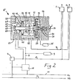
- FIG. 1 and 2 show two different exemplary embodiments for driver brake valves designed according to the invention, the same components being provided with the same reference numbers in each case.
- two pilot control valves 1 and 2 which are designed to be arbitrarily actuatable and are not pressure-maintaining2, are provided at two operating points, the structure of which is known and can, for example, correspond to the description of DE-PS 24 54 384.
- the compressed air supply to the pilot valves 1 and 2 takes place from a main container line 3 via a pressure regulator 4, the output pressure of which corresponds to a desired pressure is supplied to the pilot valves 1 and 2 via pipes 5.
- the two pilot valves 1 and 2 are connected to a common control connection 7, 8, which is divided into two sections 7 and 8 by a step valve 6, so that a pilot pressure can be controlled into the control connection 7, 8 by appropriate actuation of the pilot valves 1 and 2 is.
- the section 8 of the control connection 7, 8 facing away from the pilot valves 1 and 2 is connected to an air container 9 which increases the volume of the control connection 7, 8 and opens into a relay valve 10 in a control chamber (not shown).
- the relay valve 10 is in turn supplied with compressed air from the main container line 3 and controls the pressure in a main air line 11 in accordance with the pilot pressure supplied to it by the section 8.
- the stepped valve 6 has a piston member 12 designed as a membrane piston, which is provided with valve tappets 13 and 14 projecting on both sides.
- the pilot valve-side section 7 of the control connection 7, 8 opens into a loading chamber 15 on one side of the piston member 12; In this loading chamber 15 there is a spring 16 which loads the piston member 12.
- the valve tappet 13 extends through the loading chamber 15 and ends in front of a chamber 17 in front of a valve closing plate 18 in the chamber 17, which is provided on both sides with yildile sealing rings.
- the housing 19 of the stepped valve 6 has on both sides of the valve closing plate 18 facing valve seats 20 and 21, between which the valve closing plate 18 is movable and with which the valve closing plate 18 forms a double valve 18, 20, 21.
- the two valve lifters 13 and 14 are drilled lengthways, their interior 22 is continuously connected to the pressurizing chamber 15 via a transverse bore 23.
- the valve member-side valve 18, 20 of the double valve 18, 20, 21 monitors a large cross-sectional connection of the pressurizing chamber 15 with the chamber 17, which connection is led through the interior 22; a spring 24 which loads the valve closing plate 18 attempts to keep the valve 18, 20 closed.
- the further valve 18, 21 of the double valve 18, 20, 21 monitors a connection of the space 17 to the spring 24 receiving space 25.
- the space 17 is connected to the section 8 of the control connection 7, 8 and the space 25 is connected to the pipeline 5 carrying the set pressure.
- a throttle 27 is located in a channel 26 connecting the rooms 15 and 17 to one another; the valve 18, 20 thus monitors an unthrottled bypass to the throttle 27.
- a housing channel 28 leads to the pressure chamber 29 located on the other side of the piston member 12, which is delimited by the latter.
- valve tappet 14 slidably extends through the pressure chamber 29 and ends with one surrounding its mouth Valve seat in a space 30 in front of a double valve plate 31, which in turn is located in a space 33 continuously connected to the atmosphere via a ventilation channel 32 and which forms a double valve 14, 31, 34 with the valve tappet 14 and a valve seat 34 fixed to the housing, one part of the valve 14, 31 a connection of the pressurizing chamber 15 to the room 30 and its other valve part 14, 34 monitors a connection of the room 30 to the atmosphere.
- a bullet chamber 35 designed as an air container is connected to the space 30.
- room 33 there is a spring 36 loading double valve plate 31 in the closing direction of valve part 31, 34.
- valves 18, 20 and 18, 21 or valve parts 14, 31 and 3'1, 34 of both double valves 18, 20, 21 and 14, 31, 34 can be switched in opposite directions by the piston member 12.
- the double valve plate 31 is provided with a plunger 37, by means of which an electrical switching device 38 designed as a changeover switch can be switched; one output contact 39 is for actuating a release indicator, not shown, and the other output contact 40 is for actuating a brake, also not shown ad provided.
- the main container line 3 carries high-pressure compressed air, which is reduced to the setpoint pressure and fed into the pipe 5 by the pressure regulator 3.
- the pilot valves 1 and 2 are located. themselves in their rest position, in which they keep section 7 of the control connection 7, 8 blocked in turn.
- the open valve 18, 21 and the space 17 the target pressure from the pipeline 5 also reaches the section 8 of the control connection 7, 8 and to the relay valve 10, which consequently has a corresponding pressure level in the main air line 11 to keep the brakes released controls.
- the setpoint pressure level is also maintained in the pressurizing chamber 15 and section 7 of the control connection 7, 8 via the throttle 27.
- the pressure in section 7 of control connection 7, 8 must be reduced by actuating one of pilot valves 1 or 2; the throttle 27 also shields this effective pressure reduction from the chamber 17 in the pressurizing chamber 15, so that a pressure difference occurs on the piston member 12 which moves the piston member 12 to the left against the force of the spring 16.
- the double valve 14, 31, 34 and after the valve tappet 13 abuts the valve closing plate 18 at about the same time also the double valve 18, 20, 21 switched so that the valve 18, 21 and the valve part 31, 34 are closed and the valve 18, 20 and the valve part 14, 31 are opened.
- the throttle 27 is bridged across the interior 22 in a large cross-section, and via the open valve 14, 31 the injection chamber 35, which is separated from the atmosphere, is passed to the pressurizing chamber 15 and thus the sections 7 and 8 of the control connection, which are now unthrottled 7, 8 connected.
- Compressed air flows from the control connection 7, 8 into the injection chamber 35 until pressure equalization, as a result of which a rapid reduction in pressure is brought about in the control connection 7, 8 and thus also in the air container 9; the volume of the bullet chamber 35 is matched to the total volume of the control connection 7, 8 and the rooms connected to it in such a way that this pressure reduction is sufficient to control the first braking stage.
- the pressure drop in the control connection 7, 8 is transmitted to the main air line 11 via the relay valve 10.
- the switching device 38 is also reversed by means of the plunger 37, so that the release indicator goes out via the opening output contact 39 and the closing output contact 40 activates the brake indicator
- the subsequent braking and releasing processes can be controlled as usual by corresponding actuation of the pilot valves 1 and 2 by appropriate pressure control of the pilot pressure prevailing in the control connection 7, 8, the stepped valve 6 maintaining its switching position reached.
- the control connection 7, 8 and thus the pressurizing chamber 15 are placed just below controlled half of the desired pressure level, which is sufficient, in conjunction with the force of the spring 16, to push the piston member 12 back to the right in its initial position shown in FIG.
- the valve 18, 21 is opened again and the valve 18, 20 is closed, so that the desired pressure head pipe 5 is connected to the section 8 of the control connection 7, 8 and thus the relay valve 10, in the latter Setpoint pressure level is rapidly controlled and the relay valve 10 accordingly accordingly quickly controls the released brake corresponding pressure level in the main air line 11.
- the bullet chamber 35 is separated from the interior 22 and thus the pressurizing chamber 15 and emptied into the atmosphere via the ventilation channel 32.
- the plunger 37 switches the switching device 38 to extinguish the braking and actuation of the release indicator.
- the full set pressure is then built up again in the pressurizing chamber 15 and section 7. This completes the release process.
- Fig. 1 From Fig. 1 it can be seen that the piston member 12 is intercepted in its normal position shown on the housing 19, so mechanical overloading of the valve 18, 20 is excluded by the mechanical separation of valve tappet 13 and valve closing plate 18.
- the valve parts of the double valve 14, 31, 34 can only be loaded by the force of the spring 36 and are therefore also protected against mechanical overloads.
- the valve 18, 21 can by a resilient, not shown intermediate member between the valve closing plate 18 and the tappet 23 or by a simple, also not shown, unproblematic Interception of the valve closing plate 18 against the housing 19 are protected against overloads. In modification of these designs, however, it is also possible to firmly connect the valve closing plate 18 to the valve tappet 13.
- sections 7 and 8 can be connected to one another by means of throttle 27 1 in the manner shown in broken lines in FIG. 1; this does not change the mode of operation of the driver's brake valve.
- the driver's brake valve demonstrates Enttal of the air tank 9 by the arrangement of the throttle 27 between the sections 7 and 8 of the control connection 7, 8 still a very high responsiveness for the activation of the first braking stage with only an extremely short actuation of one of the pilot valves 1 or 2, because by this after as before only the pressure drop required to respond to the stepped valve 6 into the volume of the section 7 of the control connection 7, 8 and the relatively small pressurizing space 15 must be controlled, the throttle 27 the volume of the section 8 with the relatively large control chamber of the relay valve 10 this pressure drop a shields; in comparison to known driver brake valves, only a very small amount of air has to be discharged from the section 7 to the atmosphere by means of the pilot valves 1 or 2.
- the double valve 18, 20, 21 and the throttle 27 according to FIG. 1 are replaced by the double valve 47, 48, 51 and the throttle 46 in the embodiment according to FIG. 2.
- the piston member 12 directly actuates only the double valve monitoring the connections of the injection chamber 35, while the double valve 47, 48, 41 is actuated indirectly pneumatically by the piston member 12 through the pressurization of the piston 42 coupled to the injection chamber 35 by means of the loading chamber 44.
- the piston 42 is displaced to the right by a corresponding pressurized air supply to the pressurizing chamber 44 against the force of a spring 53 in the chamber 43 which loads the piston 42 according to FIG. 2, the valve 48, 51 shifting to the right Blocking the connection of the two spaces 50 and 45 closes and the valve 47, 48 opens to bridge the throttle 46. From this it can be deduced that the mode of operation of the driver brake valve according to FIG. 2 corresponds to that of the driver brake valve according to FIG. 1.
- the piston member 12 however, has an increased sensitivity, since it only has to switch mechanically the double valve monitoring the pressurization of the injection chamber 35.
- the spring 16 exerts an additional force on the piston member 12; If the spring 16 is omitted, this additional force can also be exerted by designing the piston member 12 as a differential piston, with the larger piston surface facing the pressurizing chamber 15.
- both double valves 14, 31 34 and 18, 20, 21 and 47, 48, 51 on one side of the piston member 12.
- the double valve 18, 20, 21 in which, in the embodiment shown, both valves 18, 20 and 18, 21 are briefly opened during switching processes to replace the double valve 47, 48, 51 corresponding to that shown in FIG. 2 with a housing-fixed and a movable valve seat, with no simultaneous open position of both valves occurring during switching processes.
- valve tappets corresponding to the valve lifters 14 and 15 according to FIG. 1 can be located on one side of the piston member 12, the valve lifters being expediently one of the valve lifters mechanically connected to the piston member and the other valve lifter is mechanically separated from the piston member; the other valve tappet expediently connects to a through-hole in the double valve plate of the double valve closer to the piston member.
- the driver's brake valve ensures that the first brake level is activated even when the pilot valves are actuated for a very short time and avoids undesired venting during loosening processes.
Landscapes
- Engineering & Computer Science (AREA)
- Transportation (AREA)
- Mechanical Engineering (AREA)
- Valves And Accessory Devices For Braking Systems (AREA)
Applications Claiming Priority (2)
| Application Number | Priority Date | Filing Date | Title |
|---|---|---|---|
| DE19843401454 DE3401454A1 (de) | 1984-01-17 | 1984-01-17 | Fuehrerbremsventil fuer schienenfahrzeuge |
| DE3401454 | 1984-01-17 |
Publications (3)
| Publication Number | Publication Date |
|---|---|
| EP0149493A2 true EP0149493A2 (fr) | 1985-07-24 |
| EP0149493A3 EP0149493A3 (en) | 1985-08-21 |
| EP0149493B1 EP0149493B1 (fr) | 1987-04-08 |
Family
ID=6225166
Family Applications (1)
| Application Number | Title | Priority Date | Filing Date |
|---|---|---|---|
| EP85100440A Expired EP0149493B1 (fr) | 1984-01-17 | 1985-01-17 | Robinet de frein de mécanicien pour véhicules sur rails |
Country Status (2)
| Country | Link |
|---|---|
| EP (1) | EP0149493B1 (fr) |
| DE (2) | DE3401454A1 (fr) |
Cited By (3)
| Publication number | Priority date | Publication date | Assignee | Title |
|---|---|---|---|---|
| FR3064964A1 (fr) * | 2017-04-10 | 2018-10-12 | Matisa Materiel Industriel S.A. | Robinet de mecanicien simplifie et circuit pneumatique de freinage d’une rame ferroviaire incorporant un tel robinet de mecanicien |
| US10625717B2 (en) | 2015-11-25 | 2020-04-21 | Mitsubishi Heavy Industries Engineering, Ltd. | Brake control device, brake control method, train, and program |
| CN115306923A (zh) * | 2022-07-05 | 2022-11-08 | 眉山中车制动科技股份有限公司 | 一种定压排气装置及其排气方法 |
Family Cites Families (2)
| Publication number | Priority date | Publication date | Assignee | Title |
|---|---|---|---|---|
| DE1605241A1 (de) * | 1966-04-07 | 1970-07-23 | Knorr Bremse Gmbh | Fuehrerbremsventileinrichtung |
| US3588184A (en) * | 1969-06-23 | 1971-06-28 | Westinghouse Air Brake Co | Locomotive brake control system suited for remote multiple unit operation |
-
1984
- 1984-01-17 DE DE19843401454 patent/DE3401454A1/de not_active Withdrawn
-
1985
- 1985-01-17 EP EP85100440A patent/EP0149493B1/fr not_active Expired
- 1985-01-17 DE DE8585100440T patent/DE3560116D1/de not_active Expired
Cited By (5)
| Publication number | Priority date | Publication date | Assignee | Title |
|---|---|---|---|---|
| US10625717B2 (en) | 2015-11-25 | 2020-04-21 | Mitsubishi Heavy Industries Engineering, Ltd. | Brake control device, brake control method, train, and program |
| EP3366507B1 (fr) * | 2015-11-25 | 2021-04-07 | Mitsubishi Heavy Industries Engineering, Ltd. | Dispositif de commande de frein, procédé de commande de frein, train, et programme |
| FR3064964A1 (fr) * | 2017-04-10 | 2018-10-12 | Matisa Materiel Industriel S.A. | Robinet de mecanicien simplifie et circuit pneumatique de freinage d’une rame ferroviaire incorporant un tel robinet de mecanicien |
| WO2018189116A1 (fr) * | 2017-04-10 | 2018-10-18 | Matisa Materiel Industriel S.A. | Robinet de mecanicien simplifie et circuit pneumatique de freinage d'une rame ferroviaire incorporant un tel robinet de mecanicien |
| CN115306923A (zh) * | 2022-07-05 | 2022-11-08 | 眉山中车制动科技股份有限公司 | 一种定压排气装置及其排气方法 |
Also Published As
| Publication number | Publication date |
|---|---|
| DE3560116D1 (en) | 1987-05-14 |
| EP0149493A3 (en) | 1985-08-21 |
| EP0149493B1 (fr) | 1987-04-08 |
| DE3401454A1 (de) | 1985-07-18 |
Similar Documents
| Publication | Publication Date | Title |
|---|---|---|
| DE102007061908B4 (de) | Parkbremse | |
| EP2058193A2 (fr) | Soupape pouvant être entraînée manuellement pour une installation de frein d'une remorque | |
| EP0352522A1 (fr) | Soupape antidérapante pour véhicules freinant à air comprimé | |
| EP0147585A2 (fr) | Soupape antidérapante pour véhicules freinant à air comprimé | |
| DE3127775A1 (de) | "betriebsbremsbeschleuniger fuer schienenfahrzeug-druckluftbremsanlagen" | |
| DE4329481C2 (de) | Pneumatische Bremseinrichtung | |
| EP0149493B1 (fr) | Robinet de frein de mécanicien pour véhicules sur rails | |
| EP0132695A2 (fr) | Valve de commande pour freins à air comprimé de véhicules sur rails | |
| DE2651377C2 (de) | Beschleuniger für ein Drei-Druck- Steuerventil von Schienenfahrzeug-Druckluftbremsanlagen | |
| EP0105118B1 (fr) | Dispositif de commande électropneumatique pour freins à air comprimé de véhicules sur rails | |
| DE2012847C3 (de) | Druckluftbremseinrichtung für Schienenfahrzeuge mit Umstellvorrichtung auf ein- oder mehrlösigen Betrieb | |
| EP0088242B1 (fr) | Installation de freinage commandée par le mécanicien pour un véhicule sur rail | |
| CH644068A5 (en) | Electro-pneumatic control device for air brakes of rail vehicles | |
| DE3326373A1 (de) | Bremssteuerventileinrichtung einer indirekt wirkenden druckluftbremse fuer schienenfahrzeuge | |
| EP0717201A2 (fr) | Système de protection dans une installation sous pression | |
| DE2616059C3 (de) | Kombinierte elektropneumatisch und rein pneumatisch wirkende Bremseinrichtung, insbesondere für Schienenfahrzeuge | |
| DE1076168B (de) | Elektropneumatische Bremseinrichtung | |
| DE2447648C2 (de) | Druckluftbremseinrichtung für Schienenfahrzeuge | |
| DE2755398C2 (de) | "Zweileitungs-Druckluftbremsanlage für Anhänger" | |
| DE910552C (de) | Steuervorrichtung fuer druckluftbetriebene Geraete, insbesondere Druckluftbremsen | |
| AT219088B (de) | Elektropneumatische Bremseinrichtung | |
| EP0335076A2 (fr) | Frein pneumatique à action directe pour véhicules ferroviaires | |
| DE2645575C2 (de) | Füllventil für Druckluftbremsen, insbesondere von Schienenfahrzeugen | |
| DE2637507A1 (de) | Elektropneumatische druckluftbremse fuer schienenfahrzeuge | |
| CH619655A5 (en) | Electropneumatic air brake for rail vehicles |
Legal Events
| Date | Code | Title | Description |
|---|---|---|---|
| PUAI | Public reference made under article 153(3) epc to a published international application that has entered the european phase |
Free format text: ORIGINAL CODE: 0009012 |
|
| PUAL | Search report despatched |
Free format text: ORIGINAL CODE: 0009013 |
|
| AK | Designated contracting states |
Designated state(s): DE FR SE |
|
| AK | Designated contracting states |
Designated state(s): DE FR SE |
|
| 17P | Request for examination filed |
Effective date: 19850626 |
|
| RAP1 | Party data changed (applicant data changed or rights of an application transferred) |
Owner name: KNORR-BREMSE AG |
|
| 17Q | First examination report despatched |
Effective date: 19860702 |
|
| GRAA | (expected) grant |
Free format text: ORIGINAL CODE: 0009210 |
|
| AK | Designated contracting states |
Kind code of ref document: B1 Designated state(s): DE FR SE |
|
| REF | Corresponds to: |
Ref document number: 3560116 Country of ref document: DE Date of ref document: 19870514 |
|
| ET | Fr: translation filed | ||
| PLBE | No opposition filed within time limit |
Free format text: ORIGINAL CODE: 0009261 |
|
| STAA | Information on the status of an ep patent application or granted ep patent |
Free format text: STATUS: NO OPPOSITION FILED WITHIN TIME LIMIT |
|
| 26N | No opposition filed | ||
| PGFP | Annual fee paid to national office [announced via postgrant information from national office to epo] |
Ref country code: SE Payment date: 19931203 Year of fee payment: 10 |
|
| PG25 | Lapsed in a contracting state [announced via postgrant information from national office to epo] |
Ref country code: SE Effective date: 19950118 |
|
| EAL | Se: european patent in force in sweden |
Ref document number: 85100440.8 |
|
| EUG | Se: european patent has lapsed |
Ref document number: 85100440.8 |
|
| PGFP | Annual fee paid to national office [announced via postgrant information from national office to epo] |
Ref country code: FR Payment date: 19990121 Year of fee payment: 15 |
|
| PGFP | Annual fee paid to national office [announced via postgrant information from national office to epo] |
Ref country code: DE Payment date: 19990326 Year of fee payment: 15 |
|
| PG25 | Lapsed in a contracting state [announced via postgrant information from national office to epo] |
Ref country code: FR Free format text: LAPSE BECAUSE OF NON-PAYMENT OF DUE FEES Effective date: 20000929 |
|
| PG25 | Lapsed in a contracting state [announced via postgrant information from national office to epo] |
Ref country code: DE Free format text: LAPSE BECAUSE OF NON-PAYMENT OF DUE FEES Effective date: 20001101 |
|
| REG | Reference to a national code |
Ref country code: FR Ref legal event code: ST |