EP0717201A2 - Système de protection dans une installation sous pression - Google Patents
Système de protection dans une installation sous pression Download PDFInfo
- Publication number
- EP0717201A2 EP0717201A2 EP95116660A EP95116660A EP0717201A2 EP 0717201 A2 EP0717201 A2 EP 0717201A2 EP 95116660 A EP95116660 A EP 95116660A EP 95116660 A EP95116660 A EP 95116660A EP 0717201 A2 EP0717201 A2 EP 0717201A2
- Authority
- EP
- European Patent Office
- Prior art keywords
- consumer circuit
- valve
- consumer
- pressure
- protection system
- Prior art date
- Legal status (The legal status is an assumption and is not a legal conclusion. Google has not performed a legal analysis and makes no representation as to the accuracy of the status listed.)
- Granted
Links
- 238000009434 installation Methods 0.000 title 1
- 230000000903 blocking effect Effects 0.000 claims abstract description 10
- 238000006073 displacement reaction Methods 0.000 claims description 5
- 230000035699 permeability Effects 0.000 claims description 5
- 230000000149 penetrating effect Effects 0.000 claims 1
- 230000002950 deficient Effects 0.000 description 13
- 238000011161 development Methods 0.000 description 9
- 230000018109 developmental process Effects 0.000 description 9
- 238000007789 sealing Methods 0.000 description 8
- 230000000694 effects Effects 0.000 description 6
- 230000007547 defect Effects 0.000 description 4
- 238000011144 upstream manufacturing Methods 0.000 description 4
- 230000005540 biological transmission Effects 0.000 description 3
- 238000004519 manufacturing process Methods 0.000 description 2
- 239000000463 material Substances 0.000 description 2
- 230000002265 prevention Effects 0.000 description 2
- 230000002411 adverse Effects 0.000 description 1
- 238000010276 construction Methods 0.000 description 1
- 230000003111 delayed effect Effects 0.000 description 1
- 230000001419 dependent effect Effects 0.000 description 1
- 239000007788 liquid Substances 0.000 description 1
- 238000011177 media preparation Methods 0.000 description 1
- 230000001681 protective effect Effects 0.000 description 1
- 230000001105 regulatory effect Effects 0.000 description 1
- 230000029058 respiratory gaseous exchange Effects 0.000 description 1
Images

Classifications
-
- F—MECHANICAL ENGINEERING; LIGHTING; HEATING; WEAPONS; BLASTING
- F15—FLUID-PRESSURE ACTUATORS; HYDRAULICS OR PNEUMATICS IN GENERAL
- F15B—SYSTEMS ACTING BY MEANS OF FLUIDS IN GENERAL; FLUID-PRESSURE ACTUATORS, e.g. SERVOMOTORS; DETAILS OF FLUID-PRESSURE SYSTEMS, NOT OTHERWISE PROVIDED FOR
- F15B20/00—Safety arrangements for fluid actuator systems; Applications of safety devices in fluid actuator systems; Emergency measures for fluid actuator systems
Definitions
- the invention relates to a protection system according to the preamble of patent claim 1.
- Positions I and II or 1 and 10 can be viewed there as overflow valves and consumer circuits assigned to them in the sense of the preamble of claim 1, for example in FIG. 1.
- the invention is suitable for pressure medium systems of the type mentioned at the outset for use in all technical fields and in connection with all liquid and gaseous pressure media.
- Compressed air is often used as a pressure medium.
- Vehicle pressure systems offer an important area of application in connection with compressed air.
- the protection system mentioned at the outset can be supplemented by one or more additional overflow valves for one or more additional consumer groups which are subordinate to the original consumer groups mentioned in the preamble of claim 1. This is dealt with in more detail below using the example of an additional overflow valve and an additional consumer circuit. These explanations apply in full to one or more additional overflow valves and the associated consumer circuits.
- a case of such a pressure medium system is given, for example, by a vehicle pressure medium system, the original (and priority) consumer circuits of the service brake circuits and the additional (and subordinate) consumer circuit of which is a spring-loaded parking brake circuit if a certain performance of the service brake circuits is required to fill the pressure medium system with atmospheric pressure before the spring-loaded parking brake circuit has sufficient pressure to release the spring-loaded brake.
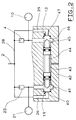
- Fig. 1 shows in solid lines the basic design of a protection system for a pressure medium system with two consumer circuits (10, 21), which are symbolized by storage containers.
- the supply device (1) contains, in a known manner, a pressure generator and any necessary pressure medium preparation devices, pressure regulating and pressure limiting devices.
- the direct connection (29) is arranged bypassing the protective valve (4), that is to say parallel to it, also between the supply device (1) and the consumer circuit (10).
- the overflow valve (4) and the direct connection (29) are connected to the supply device (1) via a supply line (2, 28).
- the shut-off device (12) is arranged in the direct connection (29) in such a way that it masters its passage.
- the shut-off device (12) can be controlled by two pressures by means of two pressure-dependent control devices (not described in more detail). Your one control device is connected to the one consumer circuit (10) via a control line (11), and your other control device is connected to the other consumer circuit (21) via a control line (20).
- the shut-off device (12) is designed such that, in the case of pressure equality, that is to say also at atmospheric pressure, the passage of the Direct connection (29) opens and closes this passage at a higher pressure in the control line (20) than in the control line (11). In other words, the shut-off device (12) is switched into a blocking position closing the passage of the direct connection (29) in favor of the consumer circuit (21) not assigned to it.
- the transmission capacity of the direct connections (26, 29) is limited in such a way that in the event of a defect in a consumer circuit (10 or 21), the supply quantity (1) flowing into the defective consumer circuit (10 or 21) in every possible delivery quantity is the supply device (1) the assigned direct connection (29 or 26) generates a dynamic pressure which produces the effect described below.
- This limitation of the transmission capacity can be achieved by suitable dimensioning of the direct connections, but also by throttling in the direct connections, as indicated by the reference numerals (31 or 24). Throttles provided, as shown, can be arranged upstream of the shut-off devices (12 or 19), but also downstream thereof.
- the entire delivery quantity of the supply device can flow via the direct connection (26) into the other, intact, consumer circuit (21).
- a consumer circuit pressure builds up in the other consumer circuit (21), which reduces the opening pressure of the associated overflow valve (23) and contributes to the safe opening of the same.
- By blocking the direct connection (29), a further escape of pressure medium via the now closed direct connection (26) and the defective consumer circuit (10) is prevented until the assigned overflow valve (4) opens, with the result that the intact consumer circuit ( 21) is filled up at least up to the (undiminished) opening pressure of the overflow valve (4) assigned to the defective consumer circuit (10).
- This opening pressure is called Safety pressure of the consumer circuit (21) is also maintained if the defect in the consumer circuit (10) occurs when the pressure medium system is full.
- Switching the shut-off device (12) assigned to the defective consumer circuit (10) just described with practically every - however small - pressure difference can be disadvantageous if both consumer circuits (10, 21) are intact.
- a certain unevenness in the build-up of consumer pressure when topping up atmospheric pressure is inevitable, for example as a result of unequal volumes of consumer groups (10, 21).
- Switching a shut-off device (12 or 19) at practically any pressure difference would interrupt the filling of the consumer circuit (10 or 21) with the respective lower consumer circuit pressure until the pressure in the supply line (2, 28) and thus the consumer circuit pressure of the other consumer circuit (10 or 21) reaches the opening pressure of the overflow valve (4 or 23) of the consumer circuit (10 or 21) with the lower consumer circuit pressure.
- shut-off devices (12 or 19) can be designed in this way.
- Secondary check valves (30 or 27) can be arranged in the direct connection assigned to a consumer circuit or in the direct connections (29 or 26) assigned to the two consumer circuits (10, 21). This secondary check valve or these secondary check valves prevent pressure medium from being supplied to the supply device (1) via the respectively assigned direct connection from the respectively assigned consumer circuit (10 or 21). or can flow into the other consumer group (21 or 10).
- the - albeit very low - flow resistance of the secondary check valve (s) (30 or 27) causes an increase in the above-mentioned dynamic pressure and therefore has an advantageous effect on the behavior of the protection system in the event of a defective consumer circuit pressure.
- the relevant additional overflow valve (8) is arranged via an additional branch (5) of the supply line to be designated in this case with (2, 5, 28) between the supply device (1) and the associated additional consumer circuit (9).
- the additional overflow valve (8) and the associated additional consumer circuit (9) are subordinate to the original overflow valves (4, 23) and the assigned consumer circuit (10, 21) by suitable measures, for example by one compared to the opening pressures of the overflow valves (4, 23 ) of the original consumer groups (10, 21) increased opening pressure.
- the one original overflow valve (4) and the assigned direct connection (29) are a check valve (14) and the other original overflow valve (23) and the assigned direct connection (26) are a check valve (18). subordinate.
- the additional overflow valve (15) is connected to the outputs of the Check valves (14, 18) connected, and consequently arranged between each check valve (14, 18) and the additional consumer circuit (17).
- the check valves (14, 18) are arranged so that they are permeable in the direction of the additional overflow valve (15) or the additional consumer circuit (17).
- the additional consumer circuit (17) receives pressure medium which has previously passed one of the original overflow valves (4, 23) or one of the direct connections (29, 26) assigned to it.
- the check valves (14, 18) arranged between the original overflow valves (4, 23) and the associated direct connections (29, 26) are responsible for a (back) flow from the additional consumer circuit (17) into the original consumer circuits (10, 21 ), but also to prevent a (cross) flow between the original consumer groups (10, 21).
- the overflow valves (8, 15) are immediate direct connections not provided.
- direct connections are possible in a manner not shown and can be used to design subordinate values by suitably designing their flow capacity.
- the additional overflow valve (8 or 15) and the associated consumer circuit (9 or 17) can stand for several additional consumer circuits. This is indicated by broken lines and labeled (7) or (13). In this case, it may be expedient to prevent a cross flow between the additional consumer circuits through the check valves upstream or downstream.
- check valves are shown with the reference numerals (6 and 16).
- the check valve (6) connected upstream or downstream of the additional overflow valve (8) or the additional overflow valves is also used Prevention of a backflow to the supply device (1) and prevention of a cross flow between the additional consumer circuit (9) or the additional consumer circuits and the original consumer circuits (10, 21).
- Check valves (3, 25) can also be connected upstream or downstream of the original overflow valves (4, 23), which prevent backflow to the supply device (1) and crossflow between the consumer circuits, including any additional ones arranged in parallel.
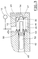
- Fig. 2 shows an embodiment of the shut-off devices (12 and 19).
- the housing (42) can be a housing specially provided for the shut-off devices (12 and 19), but in the case of the compact construction of the protection system it can also be the housing common to all components.
- one of the direct connections (29 or 26) opens into each consumer circuit chamber (41 or 46) from the right or left.
- Valve seats are arranged in the housing in a known manner surrounding the orifices. In the following, for the sake of simplicity, these valve seats are referred to as "mouth (s)".
- the orifices (47 or 40) of the direct connections (29 or 26) to be understood in this way are coaxial to one another.
- the consumer circuit chambers (41, 46) are connected to one another by a housing opening (43) running coaxially to the orifices (40, 47).
- the consumer circuit chambers (41, 46) are each connected to one of the original consumer circuits (10 or 21) and to the outlet of the respectively assigned overflow valve (4 or 23).
- a sealing body (44) is sealed in the housing opening (43) and axially displaceable between two end positions.
- a separate, unspecified, sealing element of conventional design is provided for sealing against each consumer circuit chamber (41 or 46). This type of sealing secures the consumer circuits (10, 21) against each other, since a leakage amount that may pass through one sealing element cannot pass into the other consumer circuit, but via an unidentified breathing opening of the housing opening (43) to the atmosphere, or, depending on Type of pressure medium that can escape into a collecting container with atmospheric pressure. Without this advantage, the sealing of the closing body (44) can also be carried out with only one sealing element.
- the right end position of the closing body (44) from the viewpoint of the viewer is determined by its striking against the mouth (47) of the direct connection (29).
- the left end position of the closing body (44) from the viewer's point of view is determined accordingly.
- the stop surfaces or stop lines of the closing body (44) are dimensionally and of material so that the closing body (44) over these surfaces or lines with the respectively assigned mouth (47 or 40) of the direct connections (29 or 26) each form a valve (44, 47 or 44, 40) which controls the passage between the respective direct connection (29 or 26) and the respective consumer circuit chamber (46 or 41) and thus the respective consumer circuit (10 or 21) . It is obvious that the orifices (47 or 40) must also be suitable in terms of the material used to form these valves (44, 47 or 44, 40).
- shut-off devices (12 and 19) are linked so that one is in its open position when the other is in its locked position.
- Switch springs (45) are shown on both sides in the embodiment described, but if the application requires this, a switch spring (45) can also be provided on only one side.
- FIG. 3 shows, on the example of the right-hand side from the viewpoint of the beholder, a further development of the configuration with switching spring (45) according to FIG. 2.
- the secondary check valve (30) according to FIG. 1 is integrated in the shut-off device (12).
- a secondary valve member (54) is arranged between the closing body (52) here and the mouth (47) of the direct connection (29). Together with the mouth (47), this forms the secondary check valve (30).
- the closing body (52) is shifted to the right from the perspective of the viewer by a pressure difference in favor of the consumer circuit pressure in the consumer circuit chamber (41), which is not shown but is connected to the other consumer circuit (21), its end facing the secondary valve member (54) shifts towards the secondary valve member (54) presses it against the mouth (47), thereby closes the auxiliary check valve (30) and keeps it closed, regardless of the pressures in the direct connection (29) and in the consumer circuit chamber (46).
- a driving shoulder (53) arranged on the closing body (52) grips the spring plate (50), so that both springs (45) and (51) support on the closing body (52) and determine the characteristics of the shut-off device (12).
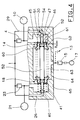
- FIG. 4 the embodiment according to FIG. 3 is developed into an embodiment in which the check valves (14, 18) required for the reordering of the additional overflow valve (15) and the associated additional consumer circuit (17) are integrated.
- the additional consumer circuit chamber (64) is connected to the additional overflow valve (15) associated with the additional consumer circuit (17) via a connection (not described in more detail), specifically to the inlet thereof.
- the valve body (60) has an unspecified cavity, which extends axially through the valve body (60) and extends coaxially to the mouth (47) of the direct connection (29) and to the valve seat (62).
- the closing body (52) is sealed and axially displaceable in this cavity.
- the valve body (60) is biased by a closing spring (63) arranged in the additional consumer circuit chamber (64) against the valve seat (62) and thus in the closing direction of the check valve (14).
- the closing spring (63) is supported on the corresponding valve body on the left-hand side from the perspective of the viewer and therefore also serves as the closing spring of the check valve (18) which can be seen on the left.
- auxiliary check valve (30) and the switching spring (45) are also provided in this embodiment, as shown, it is expedient, as shown, to support the spring plate (61) assigned to the valve body (60). Supporting the valve plate, as in FIG. 3, on the housing could have an adverse effect on the flow or flow through the check valve (14).
- the closing spring (63) must be designed so strong that it also counteracts the forces of the closing spring (51) and the switching spring (45) at atmospheric pressure or a low pressure in the additional consumer circuit chamber (64). sufficient closing force is required to securely close the check valve (14).
- the overflow valve (14) opens when, via the direct connection (29) in the consumer circuit chamber (46) and thus in the associated consumer circuit (10), a consumer circuit pressure has built up, which the pressure from the closing spring (63) overcomes the closing force exerted on the valve body (62). Due to the now possible pressure medium flow through the check valve (14), a pressure builds up via the additional consumer circuit chamber (64) up to the entrance of the additional overflow valve (15). However, this pressure is not sufficient to open the additional overflow valve (15).
- the closing spring (63) can be designed so strongly that it exerts a force on the valve body (60) that goes beyond the closing force required to close the check valve (14) properly.
- further devices such as, for example, a pressure limiting device, can be arranged between the assigned overflow valve (8) and the supply device (1), in the event that the additional consumer circuit (17) is arranged.
- Such further devices can be arranged between the check valves (14) and (18) and the associated additional overflow valve (15) without the above statements being influenced thereby.
Landscapes
- Engineering & Computer Science (AREA)
- Chemical & Material Sciences (AREA)
- Analytical Chemistry (AREA)
- Physics & Mathematics (AREA)
- Fluid Mechanics (AREA)
- Mechanical Engineering (AREA)
- General Engineering & Computer Science (AREA)
- Safety Valves (AREA)
Applications Claiming Priority (2)
| Application Number | Priority Date | Filing Date | Title |
|---|---|---|---|
| DE4445146A DE4445146A1 (de) | 1994-12-17 | 1994-12-17 | Schutzsystem für eine Druckmittelanlage |
| DE4445146 | 1994-12-17 |
Publications (3)
| Publication Number | Publication Date |
|---|---|
| EP0717201A2 true EP0717201A2 (fr) | 1996-06-19 |
| EP0717201A3 EP0717201A3 (fr) | 1998-07-01 |
| EP0717201B1 EP0717201B1 (fr) | 2002-09-11 |
Family
ID=6536169
Family Applications (1)
| Application Number | Title | Priority Date | Filing Date |
|---|---|---|---|
| EP95116660A Expired - Lifetime EP0717201B1 (fr) | 1994-12-17 | 1995-10-23 | Système de protection dans une installation sous pression |
Country Status (3)
| Country | Link |
|---|---|
| EP (1) | EP0717201B1 (fr) |
| BR (1) | BR9505889A (fr) |
| DE (2) | DE4445146A1 (fr) |
Cited By (3)
| Publication number | Priority date | Publication date | Assignee | Title |
|---|---|---|---|---|
| CN103442957A (zh) * | 2011-02-10 | 2013-12-11 | 纳薄特斯克汽车零部件有限公司 | 保护阀 |
| WO2018134096A1 (fr) * | 2017-01-17 | 2018-07-26 | Wabco Europe Bvba | Valve de protection multicircuit d'un système de freinage pneumatique |
| CN113530782A (zh) * | 2021-07-15 | 2021-10-22 | 中铁工程装备集团有限公司 | 一种具有快速压力切断保护功能的大排量泵及其保护方法 |
Families Citing this family (2)
| Publication number | Priority date | Publication date | Assignee | Title |
|---|---|---|---|---|
| DE19733778B4 (de) * | 1997-08-05 | 2004-05-06 | Bosch Rexroth Ag | Hydraulischer Pumpenabsicherungsblock |
| DE102022110263A1 (de) | 2022-04-27 | 2023-11-02 | Knorr-Bremse Systeme für Schienenfahrzeuge GmbH | Bremssystem für ein Schienenfahrzeug und Verfahren zur Ansteuerung eines solchen Bremssystems |
Citations (1)
| Publication number | Priority date | Publication date | Assignee | Title |
|---|---|---|---|---|
| DE3434884A1 (de) | 1984-09-22 | 1986-04-03 | Wabco Westinghouse Fahrzeugbremsen GmbH, 3000 Hannover | Schutzsystem fuer eine kraftfahrzeug-druckluftanlage |
Family Cites Families (4)
| Publication number | Priority date | Publication date | Assignee | Title |
|---|---|---|---|---|
| DE2206975C3 (de) * | 1972-02-14 | 1978-12-07 | Knorr-Bremse Gmbh, 8000 Muenchen | Schutzvorrichtung für Mehrkreisdruckluftleitungssysteme, insbesondere für Mehrkreisbremsanlage!! von Kraftfahrzeugen |
| DE2553818A1 (de) * | 1975-11-29 | 1977-06-02 | Wabco Westinghouse Gmbh | Mehrkreis-schutzventil fuer mehrkreis- bremsanlagen in kraftfahrzeugen |
| DE2754219C3 (de) * | 1977-12-06 | 1981-02-26 | Graubremse Gmbh, 6900 Heidelberg | Mehrkreisschutzventil für Bremsanlagen von Kraftfahrzeugen |
| DE4206172A1 (de) * | 1992-02-28 | 1993-09-02 | Bosch Gmbh Robert | Mehrkreis-schutzventil |
-
1994
- 1994-12-17 DE DE4445146A patent/DE4445146A1/de not_active Withdrawn
-
1995
- 1995-10-23 EP EP95116660A patent/EP0717201B1/fr not_active Expired - Lifetime
- 1995-10-23 DE DE59510368T patent/DE59510368D1/de not_active Expired - Lifetime
- 1995-12-14 BR BR9505889A patent/BR9505889A/pt not_active IP Right Cessation
Patent Citations (1)
| Publication number | Priority date | Publication date | Assignee | Title |
|---|---|---|---|---|
| DE3434884A1 (de) | 1984-09-22 | 1986-04-03 | Wabco Westinghouse Fahrzeugbremsen GmbH, 3000 Hannover | Schutzsystem fuer eine kraftfahrzeug-druckluftanlage |
Cited By (6)
| Publication number | Priority date | Publication date | Assignee | Title |
|---|---|---|---|---|
| CN103442957A (zh) * | 2011-02-10 | 2013-12-11 | 纳薄特斯克汽车零部件有限公司 | 保护阀 |
| EP2674338A4 (fr) * | 2011-02-10 | 2014-07-23 | Nabtesco Automotive Corp | Soupape de protection |
| US9239120B2 (en) | 2011-02-10 | 2016-01-19 | Nabtesco Automotive Corporation | Protection valve |
| CN103442957B (zh) * | 2011-02-10 | 2016-04-27 | 纳薄特斯克汽车零部件有限公司 | 保护阀 |
| WO2018134096A1 (fr) * | 2017-01-17 | 2018-07-26 | Wabco Europe Bvba | Valve de protection multicircuit d'un système de freinage pneumatique |
| CN113530782A (zh) * | 2021-07-15 | 2021-10-22 | 中铁工程装备集团有限公司 | 一种具有快速压力切断保护功能的大排量泵及其保护方法 |
Also Published As
| Publication number | Publication date |
|---|---|
| DE4445146A1 (de) | 1996-06-20 |
| BR9505889A (pt) | 1998-01-06 |
| EP0717201B1 (fr) | 2002-09-11 |
| EP0717201A3 (fr) | 1998-07-01 |
| DE59510368D1 (de) | 2002-10-17 |
Similar Documents
| Publication | Publication Date | Title |
|---|---|---|
| DE2041213A1 (de) | Unterbrecher fuer Hydraulikkreise | |
| DE19821420C1 (de) | Druckluftaufbereitungseinrichtung für Druckluftbeschaffungsanlagen auf Kraftfahrzeugen | |
| DE3434884C2 (de) | Schutzsystem für eine Kraftfahrzeug-Druckluftanlage | |
| EP0659621B1 (fr) | Dispositif de limitation de pression | |
| DE2206975C3 (de) | Schutzvorrichtung für Mehrkreisdruckluftleitungssysteme, insbesondere für Mehrkreisbremsanlage!! von Kraftfahrzeugen | |
| EP1519866B1 (fr) | Dispositif de ventilation d'un cylindre de freinage | |
| EP0641699B1 (fr) | Installation pneumatique de freinage | |
| EP0717201B1 (fr) | Système de protection dans une installation sous pression | |
| DE19710814C1 (de) | Druckluftaufbereitungseinrichtung für Druckluftbeschaffungsanlagen auf Kraftfahrzeugen | |
| DE2615893A1 (de) | Anhaenger-steuerventil | |
| DE2716796A1 (de) | Druckmittelbetaetigte bremsanlage | |
| DE3233782A1 (de) | Steuerventilanordnung, schienenfahrzeug- bzw. eisenbahnbremssystem und bremszylinderventilanordnung | |
| EP0157945B1 (fr) | Valve de commande pour remorques pour installations de freinage actionnées par fluide sur le véhicule tracteur, particulièrement installations à air comprimé | |
| EP0510326B1 (fr) | Soupape | |
| DE1923543B2 (de) | Unterbrecherventil für pneumatische Anlagen mit mehreren Verbrauchern | |
| DE19944808C1 (de) | Druckbegrenzungs- und Drucksicherungsventil für Druckluftbremsanlagen von Kraftfahrzeugen | |
| EP0600178A2 (fr) | Valve de commande pour remorques | |
| DE4125964C1 (en) | Braking system in vehicle - has multi-circuit safety valve using piston with three parallel working surfaces | |
| DE2232120A1 (de) | Vierkreis-schutzventil | |
| DE2701960C2 (de) | Stufbares Handbremsventil | |
| DE3110103A1 (de) | "blockierschutzeinrichtung | |
| EP0492068A2 (fr) | Installation à air comprimé munie d'une partie à haute pression et d'une partie à basse pression | |
| EP0574674B1 (fr) | Système de protection dans une installation sous pression | |
| DE3934242C1 (fr) | ||
| DE19649347A1 (de) | Hilfskraftlenkung für Kraftfahrzeuge |
Legal Events
| Date | Code | Title | Description |
|---|---|---|---|
| PUAI | Public reference made under article 153(3) epc to a published international application that has entered the european phase |
Free format text: ORIGINAL CODE: 0009012 |
|
| AK | Designated contracting states |
Kind code of ref document: A2 Designated state(s): DE FR GB IT SE |
|
| PUAL | Search report despatched |
Free format text: ORIGINAL CODE: 0009013 |
|
| AK | Designated contracting states |
Kind code of ref document: A3 Designated state(s): DE FR GB IT SE |
|
| 17P | Request for examination filed |
Effective date: 19980615 |
|
| RAP1 | Party data changed (applicant data changed or rights of an application transferred) |
Owner name: WABCO GMBH & CO. OHG |
|
| GRAG | Despatch of communication of intention to grant |
Free format text: ORIGINAL CODE: EPIDOS AGRA |
|
| 17Q | First examination report despatched |
Effective date: 20011127 |
|
| GRAG | Despatch of communication of intention to grant |
Free format text: ORIGINAL CODE: EPIDOS AGRA |
|
| GRAG | Despatch of communication of intention to grant |
Free format text: ORIGINAL CODE: EPIDOS AGRA |
|
| GRAH | Despatch of communication of intention to grant a patent |
Free format text: ORIGINAL CODE: EPIDOS IGRA |
|
| GRAH | Despatch of communication of intention to grant a patent |
Free format text: ORIGINAL CODE: EPIDOS IGRA |
|
| GRAA | (expected) grant |
Free format text: ORIGINAL CODE: 0009210 |
|
| AK | Designated contracting states |
Kind code of ref document: B1 Designated state(s): DE FR GB IT SE |
|
| REG | Reference to a national code |
Ref country code: GB Ref legal event code: FG4D Free format text: NOT ENGLISH |
|
| REF | Corresponds to: |
Ref document number: 59510368 Country of ref document: DE Date of ref document: 20021017 |
|
| GBT | Gb: translation of ep patent filed (gb section 77(6)(a)/1977) |
Effective date: 20021209 |
|
| ET | Fr: translation filed | ||
| PLBE | No opposition filed within time limit |
Free format text: ORIGINAL CODE: 0009261 |
|
| STAA | Information on the status of an ep patent application or granted ep patent |
Free format text: STATUS: NO OPPOSITION FILED WITHIN TIME LIMIT |
|
| 26N | No opposition filed |
Effective date: 20030612 |
|
| PGFP | Annual fee paid to national office [announced via postgrant information from national office to epo] |
Ref country code: GB Payment date: 20071017 Year of fee payment: 13 Ref country code: FR Payment date: 20071026 Year of fee payment: 13 |
|
| GBPC | Gb: european patent ceased through non-payment of renewal fee |
Effective date: 20081023 |
|
| REG | Reference to a national code |
Ref country code: FR Ref legal event code: ST Effective date: 20090630 |
|
| PG25 | Lapsed in a contracting state [announced via postgrant information from national office to epo] |
Ref country code: FR Free format text: LAPSE BECAUSE OF NON-PAYMENT OF DUE FEES Effective date: 20081031 |
|
| PG25 | Lapsed in a contracting state [announced via postgrant information from national office to epo] |
Ref country code: GB Free format text: LAPSE BECAUSE OF NON-PAYMENT OF DUE FEES Effective date: 20081023 |
|
| PGFP | Annual fee paid to national office [announced via postgrant information from national office to epo] |
Ref country code: SE Payment date: 20141016 Year of fee payment: 20 Ref country code: DE Payment date: 20141031 Year of fee payment: 20 |
|
| PGFP | Annual fee paid to national office [announced via postgrant information from national office to epo] |
Ref country code: IT Payment date: 20141014 Year of fee payment: 20 |
|
| REG | Reference to a national code |
Ref country code: DE Ref legal event code: R071 Ref document number: 59510368 Country of ref document: DE |
|
| REG | Reference to a national code |
Ref country code: SE Ref legal event code: EUG |