EP0149686A1 - Bloc de jonction pour meneau et assemblage d'un meneau dans un encadrement - Google Patents
Bloc de jonction pour meneau et assemblage d'un meneau dans un encadrement Download PDFInfo
- Publication number
- EP0149686A1 EP0149686A1 EP83112591A EP83112591A EP0149686A1 EP 0149686 A1 EP0149686 A1 EP 0149686A1 EP 83112591 A EP83112591 A EP 83112591A EP 83112591 A EP83112591 A EP 83112591A EP 0149686 A1 EP0149686 A1 EP 0149686A1
- Authority
- EP
- European Patent Office
- Prior art keywords
- fighter
- block
- frame
- foot
- profile
- Prior art date
- Legal status (The legal status is an assumption and is not a legal conclusion. Google has not performed a legal analysis and makes no representation as to the accuracy of the status listed.)
- Granted
Links
- 238000002347 injection Methods 0.000 claims abstract description 21
- 239000007924 injection Substances 0.000 claims abstract description 21
- 230000002787 reinforcement Effects 0.000 claims abstract description 17
- 238000007789 sealing Methods 0.000 claims description 23
- 150000001875 compounds Chemical class 0.000 claims description 19
- 230000000295 complement effect Effects 0.000 claims description 3
- 239000003566 sealing material Substances 0.000 abstract description 2
- XEEYBQQBJWHFJM-UHFFFAOYSA-N Iron Chemical compound [Fe] XEEYBQQBJWHFJM-UHFFFAOYSA-N 0.000 description 16
- 229910052742 iron Inorganic materials 0.000 description 8
- 230000003014 reinforcing effect Effects 0.000 description 8
- 239000000565 sealant Substances 0.000 description 8
- 230000035515 penetration Effects 0.000 description 6
- 229920003023 plastic Polymers 0.000 description 5
- 238000004519 manufacturing process Methods 0.000 description 4
- 239000000463 material Substances 0.000 description 4
- 230000007774 longterm Effects 0.000 description 3
- 230000000630 rising effect Effects 0.000 description 3
- 230000007480 spreading Effects 0.000 description 3
- 229910001229 Pot metal Inorganic materials 0.000 description 2
- 238000007373 indentation Methods 0.000 description 2
- 238000010079 rubber tapping Methods 0.000 description 2
- 230000007704 transition Effects 0.000 description 2
- DSSYKIVIOFKYAU-XCBNKYQSSA-N (R)-camphor Chemical compound C1C[C@@]2(C)C(=O)C[C@@H]1C2(C)C DSSYKIVIOFKYAU-XCBNKYQSSA-N 0.000 description 1
- 241000723346 Cinnamomum camphora Species 0.000 description 1
- HCHKCACWOHOZIP-UHFFFAOYSA-N Zinc Chemical compound [Zn] HCHKCACWOHOZIP-UHFFFAOYSA-N 0.000 description 1
- 229920000122 acrylonitrile butadiene styrene Polymers 0.000 description 1
- 230000002411 adverse Effects 0.000 description 1
- 239000012080 ambient air Substances 0.000 description 1
- 230000004888 barrier function Effects 0.000 description 1
- 230000015572 biosynthetic process Effects 0.000 description 1
- 229960000846 camphor Drugs 0.000 description 1
- 229930008380 camphor Natural products 0.000 description 1
- 230000001427 coherent effect Effects 0.000 description 1
- 238000007596 consolidation process Methods 0.000 description 1
- 239000003365 glass fiber Substances 0.000 description 1
- 230000006872 improvement Effects 0.000 description 1
- 238000003780 insertion Methods 0.000 description 1
- 230000037431 insertion Effects 0.000 description 1
- 238000000034 method Methods 0.000 description 1
- 230000000149 penetrating effect Effects 0.000 description 1
- 230000002093 peripheral effect Effects 0.000 description 1
- 230000008569 process Effects 0.000 description 1
- 239000002210 silicon-based material Substances 0.000 description 1
- 230000006641 stabilisation Effects 0.000 description 1
- 238000011105 stabilization Methods 0.000 description 1
- 239000000126 substance Substances 0.000 description 1
- 230000003313 weakening effect Effects 0.000 description 1
- 239000011701 zinc Substances 0.000 description 1
- 229910052725 zinc Inorganic materials 0.000 description 1
Images

Classifications
-
- E—FIXED CONSTRUCTIONS
- E06—DOORS, WINDOWS, SHUTTERS, OR ROLLER BLINDS IN GENERAL; LADDERS
- E06B—FIXED OR MOVABLE CLOSURES FOR OPENINGS IN BUILDINGS, VEHICLES, FENCES OR LIKE ENCLOSURES IN GENERAL, e.g. DOORS, WINDOWS, BLINDS, GATES
- E06B3/00—Window sashes, door leaves, or like elements for closing wall or like openings; Layout of fixed or moving closures, e.g. windows in wall or like openings; Features of rigidly-mounted outer frames relating to the mounting of wing frames
- E06B3/96—Corner joints or edge joints for windows, doors, or the like frames or wings
- E06B3/9616—Corner joints or edge joints for windows, doors, or the like frames or wings characterised by the sealing at the junction of the frame members
Definitions
- the invention relates to a fighter block according to the preamble of claim 1 and a fighter connection according to the preamble of claim 7.
- a fighter is a strut between two opposite support structures. Particularly in window frames, such a fighter can be used, for example, to divide a window into two window halves or into several window areas as an intermediate strut for connecting opposite window frame areas.
- Fighter block is understood below to mean the block-like or block-like connecting piece which is fastened to the frame for attaching the end region of the fighter.
- a generic fighter block is known from DE 32 12 436.8 A1.
- This fighter block is in many respects already a largely satisfactory connection between the hollow profile of the fighter and the window frame, which is usually designed as a hollow profile.
- the sealing problem in this known fighter connection has not yet been satisfactorily solved.
- the mechanical connection of the fighter block to the frame profile still needs improvement, e.g. to better absorb the torsional forces that occur when opening or closing a window sash on the fighter connection.
- the term “outside” in the case of the fighter connection is understood to mean the surface facing outward, for example in the case of a window frame, which is exposed to the weather. Accordingly, “inside” is understood to mean the surface of a window frame or the fighter connection oriented towards the room side.
- the claimed fighter connection can be used primarily with two or more window frames with window sashes. However, the application is not limited to this, but can be used wherever cross-connections with mechanical stress and a good seal to the interior and the interior profile of the beam are involved.
- the invention has for its object to construct a fighter block and a resulting fighter connection so that the long-term behavior of the fighter block in the fighter connection is improved.
- the main idea of the invention is to design the fighter's block in the foot area and in particular on its base area with interconnected depression zones. It is essential that the depression zones are connected to one another via an injection opening and that the opening can be sealed off from the internal cavity of the fighter block by means of a sealing compound brought through the injection opening.
- the recess zones can areally extending to the opposite longitudinal attachment areas of the K ämpferklotzes and on the other hand extend through lateral recesses into the longitudinally oriented side faces on the one hand.
- a sealing compound is injected via the injection opening and the depression zones after the fighter block has been inserted into the frame profile, which is preferably of a positive fit.
- this sealant is still very free-flowing to plastic, with subsequent plasticization or a consolidation or hardening step creating a plastic to elastic seal.
- This preferably elastic sealing compound seals, so to speak, the footprint of the fighter block almost flat against the frame.
- a sealed fighter block By sealing the injection opening, which is advantageously arranged approximately in the axis of the hollow profile of the fighter block, and rising on the side walls and possibly even the closure of the fastening openings by the sealing compound, a sealed fighter block is produced.
- This sealed fighter block prevents moisture from rising through the injection opening into the inner cavity of the guide stump and into the hollow profile of the actual fighter or any internal reinforcing iron that may be present. Due to the rising of the sealant, which is still easy to flow, on the side walls, the seal can even be achieved with the actual hollow profile of the fighter.
- the fastening means for example self-tapping screws, are screwed through the sealing compound into the hollow profile of the frame, so that penetration of Moisture and aggressive ambient air in the frame is prevented by the sealant.
- This sealant attachment of the fighter block on the frame is mechanically improved by the fact that on the inside in the longitudinal orientation of the foot of the fighter block a longitudinal web is formed on the base area of the fighter block, which is at least partially form-fitting in an open annular groove in the profile of the frame towards the fighter block intervenes.
- This groove or the longitudinal web of the fighter block come to lie in the installed state on the inside of the corresponding frame connection, so that on the outside the direct hollow profile placed or pushed onto the guide stump of the fighter block extends to the foot of the fighter block and there preferably by means of the sealing compound against the Fighter block is sealed.
- the longitudinal web is arranged transversely to the actual foot of the fighter block with an intermediate distance from it. Due to the greater distance between the longitudinal web and the axis of the fighter block, which can coincide with the injection opening, torsional forces such as occur, for example, when opening and closing window sashes, are better absorbed by the foot and longitudinal web of the fighter block, which are largely positively inserted into the frame. The mechanical resilience and thus also the long-term behavior of a fighter connection designed in this way are therefore considerably improved.
- the guide stump of the fighter block advantageously merges into the foot with a base that is larger in cross section than the guide stump.
- the step-like transition between the base and the guide block-the fighter block is intended to serve as a support or abutment surface for a commonly available internal reinforcement iron of the fighter.
- the chamber wall of the corresponding hollow profile of the fighter applied over the guide stump and the base is preferably received in a form-fitting manner in an intermediate region between the wedge-shaped base and the fastening regions.
- the fastening areas therefore, with their folds running approximately parallel to the guide stump, form a snug fit or clamp seat guide that narrows trapezoidally to the foot of the fighter block.
- both the wedge-shaped areas of the base can have guide grooves and the base connection to the longitudinal web can be provided with groove recesses into which corresponding reinforcing webs of the inner profile of the fighter can engage in a form-fitting manner.
- This positive engagement of the end region of the fighter with the base already fixes the fighter relatively axially. What is more important, however, is the positive and non-positive connection of the hollow fighter profile to the fighter block against torsional forces acting on the longitudinal axis of the guide stump.
- the inner profile of the fighter is expediently also provided on the near outer side until it rests on the foot of the fighter block.
- the hollow profile wall lying directly on the outside is designed with an acute-angled bevel in relation to the axially extending inner wall of the hollow profile of the fighter.
- This bevel largely or completely covers an adjoining upper inclined surface of the frame.
- the fighter block which is preferably manufactured as a one-piece zinc die-cast part, therefore connects the external fastening options located outside the fighter hollow profile with improved mechanical stability, in particular with regard to torsional forces, but also to the engagement of the hollow fighter profile on the guide stump or base of the fighter block, which is largely axially positively connected with a clamp fit.
- the sealing of the fighter block essentially prevents the penetration of moisture and other substances attacking the material of the hollow fighter profile and any existing internal reinforcement in the area of its base.
- a silicone-based material is preferably used as the sealing compound, which is cross-linked to form an elastic compound after penetration between the fighter block and the frame.
- the injection opening is expediently formed on the foot side in the inner cavity of the guide stump of the fighter block.
- the flow paths of the sealant to be injected can be kept approximately the same length.
- the depression zones provided as flow paths in the base of the fighter block are quite schematically formed approximately in a cross shape between the fastening areas and the side surfaces running in the longitudinal direction. In this case, the depression zones opening out in the region of the injection opening are formed the deepest at this point, but they become smaller, in particular as the fastening openings preferably with a defined border.
- the injection opening of the sealing material can also be provided, for example, in combination with a correspondingly inclined fastening opening. In this case the flow zones would have to be modified accordingly.
- other materials e.g. an ABS plastic with or without glass fiber reinforcement can be used.
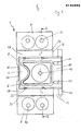
- Strength in F. 1 shows a fighter block made in one piece, for example from a die-cast zinc.
- the fighter block 1 consists essentially of a foot 7 with an elongated rectangular configuration.
- a base 5 is provided approximately symmetrically to the transverse axis, from which a substantially hollow guide stump 6 according to FIG. 1 protrudes from the plane of the drawing.
- the F EADERSHIP blunt 6 and base 5 have the function to take the hollow profile of aufdin fighter largely form-fitting manner.
- the base 5 has a roughly rectangular shape in plan view, which projects in Fig. 1 to the right over a side surface 12 of the foot 7 of the fighter block.
- a longitudinal web 24 is integrally formed with its outer edge in the longitudinal direction.
- the fastening areas 8 are each formed with two fastening openings 36.
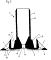
- the attachment areas 8 have a section (cf. FIG. 2) of a wedge shape tapering outwards in the longitudinal direction.
- the fastening fold 37 lying adjacent to the base 5 runs approximately parallel to the guide stump 6, that is to say. it projects approximately vertically from the foot 7 of the fighter block 1.
- the peripheral wall of the base 5 is provided with a slight widening in the direction of the foot, so that thereby an inclined surface 15 is formed, which takes over the leadership of the end region of the fighter when the hollow profile of the fighter is put on.
- the hollow profile wall between the fastening fold 37 and the inclined surface 15 of the base 5 is therefore held in the intermediate region 28 in the manner of a clamp seat.
- the guide stump 6 has, in plan view according to FIG. 1, approximately the outline of a rectangle which has an approximately semicircular wall indentation on the outward side, on the left in FIG. 1.
- the wall recess is primarily intended for the application of an ejector pin for design reasons.
- the indentation can advantageously also be used for the profile-complementary engagement of a correspondingly designed internal reinforcement profile of the fighter.
- the upper region of the guide stump 6 is slightly beveled.
- rib-like elevations 33 are formed on the side surfaces of the guide stump 6 which run in the axial direction and which can bridge tolerance differences in the inside diameter of a reinforcing iron to be put on, but at the same time do not allow the frictional forces to be overcome when the fighter is slid on.
- the inner cavity of the guide stump 6 merges in the direction of the foot 7 via a funnel-shaped constriction into an opening 13 which extends as far as the standing surface 9 of the fighter block 1 and which is used as an injection opening for the sealing compound during the assembly of the fighter block 1 in the frame profile.
- the side surface of the guide stump 6 lying on the right in FIG. 1 terminates approximately with the side surface 12 of the foot 7.
- the base connection 14 protruding beyond the base 7 has two fitting grooves 21 which extend in the transverse direction from right to left and which end in a wedge shape at the corresponding corner region of the right side surface of the guide stump 6.
- Slightly arcuate guide grooves 22 are provided in the inclined surfaces 15 of the base 5 oriented toward the fastening regions 8.
- These guide grooves 22 as well as the fitting grooves 21 serve to receive reinforcement elevations or reinforcement webs which are provided in an inwardly projecting manner on the hollow profile of the fighter.
- the base surface extending in a plane, the web surface between the guide cone 6 and the inclined surface 15 of the base 5 is held at least as wide to setting up a mecanicverstärkun s->s g 3 (Fig. 3) to provide.
- the inclined surface 15 of the base 5 merges into the guide stump 6 in steps.
- This step-like transition is ämpfer as a stop or seating surface for the formed usually also as a hollow profile inner reinforcement iron of the fighter in deferred K.
- the inner cavity of the guide stump 6 merges into the injection opening 13 in a funnel shape.
- the standing surface side 9 of the fighter block 1 is formed with coherent recess zones 10, which merge into the injection opening 13 with an increasingly larger recess.
- the V are flash zone ertie- made wider 10 so that spreading and Flow of the injected sealant into these areas is facilitated.
- the recess zones 10 provided in the transverse direction merge into the outward-facing side surface 11 with an approximately flat rectangular opening 17, the rise of an injected sealant on the outer surface 11 in the direction of the base 5 by the formation of a recess 18 in the sense of an ascent channel is facilitated.
- the corresponding transverse opening of the depression zone 10 widens, so that, taking into account the injection opening 13 which is slightly offset to this side, the sealant flows out or is squeezed out into this area.
- the frame 4 produced as a hollow plastic profile with several chambers, extends vertically into the plane of the drawing.
- the internal profile of the fighter with a Verstärkun g Seisen provided, whose cross-sectional contour normal to the axis of the fighter pad 1, the outer contour of the guide cone 6 is adapted.
- This inner reinforcing iron 3 is preferably provided with an axially extending longitudinal slot, so that tolerance deviations in the inner reinforcements of the fighter hollow profile can be better balanced and produced by spreading forces of the I nnenversträkungseisens that tend to a broadening of the longitudinal gap, a force-locking contact of the inner reinforcing iron against the pushed over the hollow section of the fighter becomes.
- the spreading forces on the lower end region of the inner reinforcing iron 3 can also result from being pushed onto the guide stump 6 of the fighter block 1.
- the transverse leg of this L-shape is matched approximately to the width of the foot 7 of the fighter block 1, so that the Fighter block 1 or its foot 7 is received in it with a more or less strong clamping fit.
- the vertical leg of the L-shape of the hollow frame profile which ends in the region of the guide stump 6 and can protrude, for example, 2 to 3 cm from the bearing surface of the frame 4 for the foot 7 of the fighter block 1, has an inclined surface 29 at the upper end as part of a closed hollow profile chamber on.
- the inclined surface 29 has its highest elevation on the inside oriented towards the fighter block 1 and therefore falls off towards the outer surface of the frame 4.
- the inner wall of the frame 4 which likewise has a plurality of closed chambers, is formed on the upper region with a U-shaped groove 25 which is slightly undercut or dovetail-shaped in section.
- the longitudinal web 24 engages at least partially in the recess in the groove 25.
- the fighter block 1 with its foot 7 and the longitudinal web 24 is first inserted into the L -shaped profile of the frame 4.
- the sealing compound is now injected or pressed into the depression zones 10 through the injection opening 13 in the direction of the standing surface 9 of the fighter block.
- the sealing compound can be injected until it penetrates through the recess 18 or the intermediate distance 23 between the longitudinal web 24 and the side surface 12 onto the corresponding side surfaces.
- the sealing compound is injected until sealing compound can also be ascertained in the fastening openings 36, or until these are closed on the bottom side.
- the sealing compound which is relatively free-flowing during the injection process, is crosslinked to form a sealing compound with largely elastic properties
- the fighter block 1 and in particular its inner cavity are now excellently sealed on the base side against the ingress of moisture.
- the fighter block 1 is further fixed in the frame profile by the networked sealing compound.
- the fighter block can now be fastened in the frame 4, for example by means of self-tapping screws, or the fighter hollow profile 2, including any internal reinforcement 3 that may be present, can be attached to the guide stump 6 in a non-positive and, to a large extent, positive fit, and only then the fighter block 1 screwed to the frame.
- the hollow hollow section 2 including the inner reinforcement 3 is pushed onto the guide stump 6 or the base 5 in such a way that the inner reinforcement 3 rests as flat as possible on the surface of the base 5.
- the wall of the directly from The inner reinforcement 3 reinforced hollow profile chamber of the fighter 2 is brought over the inclined surface 15 of the base 5 up to the stop against the foot 7 of the fighter block 1. In this way is taken up like a clamping fit between the respective efest Trentsfalzen B 37 and the inclined surface 15, the profile wall of the fighter. 2
- the chamber profile of the fighter 2 pointing to the outside has an acute-angled bevel 27.
- This bevel 27 extends from the outer chamber wall 42 via the outer hollow profile 26 to the inner chamber wall 43.
- this inner chamber wall 43 extends to the foot 7 of the fighter block 1, so that possibly under adverse conditions against the inclination of the Inclined surface 29 moisture or moisture entering the fighter connection on the closed inner chamber wall 43 to the foot region of the fighter block 1 is discharged.
- penetration into the fighter block 1 or into the inner cavity of the fighter 2 or along the fastening path into the frame 4 is no longer possible due to the elastic seal present.
- This sealing can be further improved by introducing the sealing compound into the area of contact with the walls of the hollow fighter profile.
- the outward-facing bevel 27 of the hollow hollow profile therefore almost completely covers the upper inclined surface 29 of the frame 4 with a complementary inclination, so that under normal conditions a run-off edge is thereby already created, which allows rain to run out onto it.
- the hollow sections von'Rahmen and K are ämpfer usually from an extrudable form stable plastic, e.g. a PVC.
- the fighter connection can also be used with other materials. If necessary, it can be advantageous in the region of the guide stump to attach a second transverse screw connection through the profile wall of the fighter, its internal reinforcement and the guide stump itself.
- the base 5 In addition to the continuous chamber wall 43 which extends to the foot 7 of the fighter block 1 and protects an inner reinforcement profile 3 of the fighter 2 from moisture, the base 5 also contributes to this. Since the internal reinforcement profile 3 rests on the surface of the base 5, direct contact with moisture that possibly penetrates into the foot area is thereby avoided.
Landscapes
- Engineering & Computer Science (AREA)
- Civil Engineering (AREA)
- Structural Engineering (AREA)
- Door And Window Frames Mounted To Openings (AREA)
- Load-Bearing And Curtain Walls (AREA)
- Mutual Connection Of Rods And Tubes (AREA)
Priority Applications (3)
| Application Number | Priority Date | Filing Date | Title |
|---|---|---|---|
| EP83112591A EP0149686B1 (fr) | 1983-12-14 | 1983-12-14 | Bloc de jonction pour meneau et assemblage d'un meneau dans un encadrement |
| AT83112591T ATE33055T1 (de) | 1983-12-14 | 1983-12-14 | Kaempferklotz und kaempferverbindung. |
| DE8383112591T DE3376029D1 (en) | 1983-12-14 | 1983-12-14 | Joining piece for mullions, and connection of a mullion within a frame |
Applications Claiming Priority (1)
| Application Number | Priority Date | Filing Date | Title |
|---|---|---|---|
| EP83112591A EP0149686B1 (fr) | 1983-12-14 | 1983-12-14 | Bloc de jonction pour meneau et assemblage d'un meneau dans un encadrement |
Publications (2)
| Publication Number | Publication Date |
|---|---|
| EP0149686A1 true EP0149686A1 (fr) | 1985-07-31 |
| EP0149686B1 EP0149686B1 (fr) | 1988-03-16 |
Family
ID=8190877
Family Applications (1)
| Application Number | Title | Priority Date | Filing Date |
|---|---|---|---|
| EP83112591A Expired EP0149686B1 (fr) | 1983-12-14 | 1983-12-14 | Bloc de jonction pour meneau et assemblage d'un meneau dans un encadrement |
Country Status (3)
| Country | Link |
|---|---|
| EP (1) | EP0149686B1 (fr) |
| AT (1) | ATE33055T1 (fr) |
| DE (1) | DE3376029D1 (fr) |
Cited By (4)
| Publication number | Priority date | Publication date | Assignee | Title |
|---|---|---|---|---|
| DE3513274A1 (de) * | 1985-04-13 | 1986-10-23 | Niemann, Hans Dieter, 5014 Kerpen | Rahmen fuer fenster oder tueren |
| DE4014317C1 (fr) * | 1990-05-04 | 1991-06-20 | Deflex-Dichtsysteme Gmbh, 4100 Duisburg, De | |
| EP0569957A1 (fr) * | 1992-05-15 | 1993-11-18 | Pax GmbH | Accouplement vissé pour profilés creux en matière plastique |
| DE19938218A1 (de) * | 1999-08-12 | 2001-02-15 | Hans Dieter Niemann | T-Verbindung von Hohlprofilstäben und Verfahren zum Herstellen einer T-Verbindung |
Citations (6)
| Publication number | Priority date | Publication date | Assignee | Title |
|---|---|---|---|---|
| FR1125403A (fr) * | 1954-05-11 | 1956-10-30 | Bois Metal Soc Ind | Fenêtres à cadre métallique sans soudure, ouvrant bois avec joint caoutchouc moulure |
| DE2500937A1 (de) * | 1975-01-11 | 1976-07-15 | Uhl Kg Geb | Eck- oder sprossenverbindung von rahmenprofilen |
| DE2840656A1 (de) * | 1978-09-19 | 1980-03-27 | Weru Gmbh & Co Kg | Rahmen fuer fenster, tueren u.dgl. |
| DE3013079A1 (de) * | 1980-04-03 | 1981-10-15 | Gebrüder Uhl GmbH & Co KG, 7981 Vogt | Profilschiene, insbesondere wetterschutzschiene oder bodenschwelle |
| EP0052597A1 (fr) * | 1980-10-07 | 1982-05-26 | Hans-Dieter Klingler | Joint droit entre deux profilés de cadre |
| BE894520A (nl) * | 1982-09-29 | 1983-01-17 | Profel N V | Tussenstijlverbinding voor raamkonstrukties |
-
1983
- 1983-12-14 DE DE8383112591T patent/DE3376029D1/de not_active Expired
- 1983-12-14 AT AT83112591T patent/ATE33055T1/de not_active IP Right Cessation
- 1983-12-14 EP EP83112591A patent/EP0149686B1/fr not_active Expired
Patent Citations (6)
| Publication number | Priority date | Publication date | Assignee | Title |
|---|---|---|---|---|
| FR1125403A (fr) * | 1954-05-11 | 1956-10-30 | Bois Metal Soc Ind | Fenêtres à cadre métallique sans soudure, ouvrant bois avec joint caoutchouc moulure |
| DE2500937A1 (de) * | 1975-01-11 | 1976-07-15 | Uhl Kg Geb | Eck- oder sprossenverbindung von rahmenprofilen |
| DE2840656A1 (de) * | 1978-09-19 | 1980-03-27 | Weru Gmbh & Co Kg | Rahmen fuer fenster, tueren u.dgl. |
| DE3013079A1 (de) * | 1980-04-03 | 1981-10-15 | Gebrüder Uhl GmbH & Co KG, 7981 Vogt | Profilschiene, insbesondere wetterschutzschiene oder bodenschwelle |
| EP0052597A1 (fr) * | 1980-10-07 | 1982-05-26 | Hans-Dieter Klingler | Joint droit entre deux profilés de cadre |
| BE894520A (nl) * | 1982-09-29 | 1983-01-17 | Profel N V | Tussenstijlverbinding voor raamkonstrukties |
Cited By (6)
| Publication number | Priority date | Publication date | Assignee | Title |
|---|---|---|---|---|
| DE3513274A1 (de) * | 1985-04-13 | 1986-10-23 | Niemann, Hans Dieter, 5014 Kerpen | Rahmen fuer fenster oder tueren |
| DE4014317C1 (fr) * | 1990-05-04 | 1991-06-20 | Deflex-Dichtsysteme Gmbh, 4100 Duisburg, De | |
| EP0454940A1 (fr) * | 1990-05-04 | 1991-11-06 | DEFLEX-DICHTSYSTEME GmbH | Dispositif d'assemblage de cadre et montant de rive |
| EP0569957A1 (fr) * | 1992-05-15 | 1993-11-18 | Pax GmbH | Accouplement vissé pour profilés creux en matière plastique |
| DE19938218A1 (de) * | 1999-08-12 | 2001-02-15 | Hans Dieter Niemann | T-Verbindung von Hohlprofilstäben und Verfahren zum Herstellen einer T-Verbindung |
| EP1076151A3 (fr) * | 1999-08-12 | 2002-01-23 | Niemann, Hans Dieter | Joint en T pour profilés creux et son mode d'assemblage |
Also Published As
| Publication number | Publication date |
|---|---|
| EP0149686B1 (fr) | 1988-03-16 |
| ATE33055T1 (de) | 1988-04-15 |
| DE3376029D1 (en) | 1988-04-21 |
Similar Documents
| Publication | Publication Date | Title |
|---|---|---|
| EP1020575B1 (fr) | Connection en T entre un poteau et une traverse profilés d'une façade ou d'une toiture vitrée | |
| EP0100991A2 (fr) | Profil composé | |
| EP1346112A2 (fr) | Fa ade ou toit a baguette d'etancheite pourvue d'une piece de remplissage | |
| EP1026357B1 (fr) | Profilé d'encadrement pour fenêtres ou portes en bois-métal | |
| DE3517861C2 (fr) | ||
| DE102015007804B3 (de) | Stoßverbinder für Kleberinjektion sowie Stoßverbinderkombination und Rahmen | |
| EP0052597A1 (fr) | Joint droit entre deux profilés de cadre | |
| DE19615378C2 (de) | Dichtkörper für einen Anschluß zwischen einem Pfostenprofil und einem Fenster- oder Türrahmenprofil | |
| EP0149686B1 (fr) | Bloc de jonction pour meneau et assemblage d'un meneau dans un encadrement | |
| DE10223038B4 (de) | Fassadenkonstruktion mit einem durch ein Dichtelement abgedichteten riegelseitigen Isolierprofil | |
| DE7603838U1 (de) | Rahmen, insbesondere fuer tueren und schwenkfenster | |
| DE19828382C2 (de) | Anordnung zum Befestigen eines einen Hohlquerschnitt aufweisenden Pfostens am Blendrahmen eines Fensters oder einer Türe aus Kunststoff oder Leichtmetall | |
| DE4106282C2 (de) | Mechanische Verbindung von mit einschiebbaren metallischen Verstärkungshohlprofilen versehenen Kunststoffhohlprofilen, insbesondere für Fenster-, Tür- od. dgl. -Rahmen | |
| EP1437449A2 (fr) | Elément d'étanchéité pour une construction à traverses et montants se composant de profilés similaires | |
| EP0844358A1 (fr) | Connexion pour profilés creux se raccordant sous un angle | |
| DE9014643U1 (de) | Eckschweißverbinder zum Verbinden zweier auf Gehrung geschnittener Hohlkammerprofile | |
| EP0110295A2 (fr) | Cadre d'espacement pour vitrage isolant dont les bords sont collés | |
| DE102016015624B4 (de) | Dichtungselement für Fassaden | |
| DE3212436A1 (de) | Kaempferklotz | |
| EP1126127A2 (fr) | Assemblage d'angle de profilés de bois | |
| DE2030746A1 (de) | Fensterrahmen aus Kunststoff mit einer Verstärkungseinlage, welche zugleich Zentralverschluß ist | |
| DE3727509C2 (de) | Filterrahmen-Gitterwerk | |
| DE8716012U1 (de) | Rahmenkonstruktion in Pfosten-Riegel-Bauweise, insbesondere für Fassaden, Dächer, Fensterwände od. dgl. | |
| EP4299871B1 (fr) | Structure de cadre faisant partie d'un élément de panneau pour une lame de porte sectionnelle | |
| DE102022117776B3 (de) | Dichtungselement mit entwässerungsmittel |
Legal Events
| Date | Code | Title | Description |
|---|---|---|---|
| PUAI | Public reference made under article 153(3) epc to a published international application that has entered the european phase |
Free format text: ORIGINAL CODE: 0009012 |
|
| AK | Designated contracting states |
Designated state(s): AT BE CH DE FR GB IT LI NL |
|
| 17P | Request for examination filed |
Effective date: 19850917 |
|
| 17Q | First examination report despatched |
Effective date: 19861106 |
|
| RAP1 | Party data changed (applicant data changed or rights of an application transferred) |
Owner name: FEB FENSTER- UND ELEMENTEBAU GMBH & CO. KG |
|
| GRAA | (expected) grant |
Free format text: ORIGINAL CODE: 0009210 |
|
| AK | Designated contracting states |
Kind code of ref document: B1 Designated state(s): AT BE CH DE FR GB IT LI NL |
|
| PG25 | Lapsed in a contracting state [announced via postgrant information from national office to epo] |
Ref country code: NL Effective date: 19880316 Ref country code: IT Free format text: LAPSE BECAUSE OF FAILURE TO SUBMIT A TRANSLATION OF THE DESCRIPTION OR TO PAY THE FEE WITHIN THE PRESCRIBED TIME-LIMIT;WARNING: LAPSES OF ITALIAN PATENTS WITH EFFECTIVE DATE BEFORE 2007 MAY HAVE OCCURRED AT ANY TIME BEFORE 2007. THE CORRECT EFFECTIVE DATE MAY BE DIFFERENT FROM THE ONE RECORDED. Effective date: 19880316 Ref country code: BE Effective date: 19880316 |
|
| REF | Corresponds to: |
Ref document number: 33055 Country of ref document: AT Date of ref document: 19880415 Kind code of ref document: T |
|
| REF | Corresponds to: |
Ref document number: 3376029 Country of ref document: DE Date of ref document: 19880421 |
|
| ET | Fr: translation filed | ||
| GBT | Gb: translation of ep patent filed (gb section 77(6)(a)/1977) | ||
| NLV1 | Nl: lapsed or annulled due to failure to fulfill the requirements of art. 29p and 29m of the patents act | ||
| PLBE | No opposition filed within time limit |
Free format text: ORIGINAL CODE: 0009261 |
|
| STAA | Information on the status of an ep patent application or granted ep patent |
Free format text: STATUS: NO OPPOSITION FILED WITHIN TIME LIMIT |
|
| 26N | No opposition filed | ||
| PGFP | Annual fee paid to national office [announced via postgrant information from national office to epo] |
Ref country code: CH Payment date: 20001130 Year of fee payment: 18 |
|
| PGFP | Annual fee paid to national office [announced via postgrant information from national office to epo] |
Ref country code: GB Payment date: 20001213 Year of fee payment: 18 |
|
| PGFP | Annual fee paid to national office [announced via postgrant information from national office to epo] |
Ref country code: AT Payment date: 20001219 Year of fee payment: 18 |
|
| PGFP | Annual fee paid to national office [announced via postgrant information from national office to epo] |
Ref country code: FR Payment date: 20001229 Year of fee payment: 18 Ref country code: DE Payment date: 20001229 Year of fee payment: 18 |
|
| PG25 | Lapsed in a contracting state [announced via postgrant information from national office to epo] |
Ref country code: GB Free format text: LAPSE BECAUSE OF NON-PAYMENT OF DUE FEES Effective date: 20011214 Ref country code: AT Free format text: LAPSE BECAUSE OF NON-PAYMENT OF DUE FEES Effective date: 20011214 |
|
| PG25 | Lapsed in a contracting state [announced via postgrant information from national office to epo] |
Ref country code: LI Free format text: LAPSE BECAUSE OF NON-PAYMENT OF DUE FEES Effective date: 20011231 Ref country code: CH Free format text: LAPSE BECAUSE OF NON-PAYMENT OF DUE FEES Effective date: 20011231 |
|
| REG | Reference to a national code |
Ref country code: GB Ref legal event code: IF02 |
|
| PG25 | Lapsed in a contracting state [announced via postgrant information from national office to epo] |
Ref country code: DE Free format text: LAPSE BECAUSE OF NON-PAYMENT OF DUE FEES Effective date: 20020702 |
|
| GBPC | Gb: european patent ceased through non-payment of renewal fee |
Effective date: 20011214 |
|
| REG | Reference to a national code |
Ref country code: CH Ref legal event code: PL |
|
| PG25 | Lapsed in a contracting state [announced via postgrant information from national office to epo] |
Ref country code: FR Free format text: LAPSE BECAUSE OF NON-PAYMENT OF DUE FEES Effective date: 20020830 |
|
| REG | Reference to a national code |
Ref country code: FR Ref legal event code: ST |