EP0149701A2 - Aiguille à clapet pour les machines textiles formant des mailles - Google Patents
Aiguille à clapet pour les machines textiles formant des mailles Download PDFInfo
- Publication number
- EP0149701A2 EP0149701A2 EP84105617A EP84105617A EP0149701A2 EP 0149701 A2 EP0149701 A2 EP 0149701A2 EP 84105617 A EP84105617 A EP 84105617A EP 84105617 A EP84105617 A EP 84105617A EP 0149701 A2 EP0149701 A2 EP 0149701A2
- Authority
- EP
- European Patent Office
- Prior art keywords
- needle
- tongue
- spoon
- latch
- bearing bore
- Prior art date
- Legal status (The legal status is an assumption and is not a legal conclusion. Google has not performed a legal analysis and makes no representation as to the accuracy of the status listed.)
- Granted
Links
Images

Classifications
-
- D—TEXTILES; PAPER
- D04—BRAIDING; LACE-MAKING; KNITTING; TRIMMINGS; NON-WOVEN FABRICS
- D04B—KNITTING
- D04B15/00—Details of, or auxiliary devices incorporated in, weft knitting machines, restricted to machines of this kind
- D04B15/06—Sinkers
-
- D—TEXTILES; PAPER
- D04—BRAIDING; LACE-MAKING; KNITTING; TRIMMINGS; NON-WOVEN FABRICS
- D04B—KNITTING
- D04B35/00—Details of, or auxiliary devices incorporated in, knitting machines, not otherwise provided for
- D04B35/02—Knitting tools or instruments not provided for in group D04B15/00 or D04B27/00
- D04B35/04—Latch needles
Definitions
- the invention relates to a latch needle for stitch-forming textile machines, with a needle shaft and with a bearing bore in a longitudinal slot of the needle shaft that is pivoted undamped about a tongue axis and has a bearing bore, which in the closed position with its spoon on the needle hook and in the reserve with the tongue back rests on contact surfaces in the area of the upper edge of the needle shaft.
- the tongue of the latch needle is exposed to very high loads.
- the needle tongue is pivoted between its closed position and its reserve at a frequency of up to 60 Hz and more, as is customary today, high acceleration and deceleration forces occur on the needle tongue.
- These not only stress the needle tongue on bending, but there are considerable energies when the spoon hits the hook or the tongue back on the contact surfaces provided on the needle shaft absorbed by bending elastic deformation and destroyed by friction.
- g tongue breaks or damage to the Zonnelagerun and the needle shaft, occur.
- the object of the invention is therefore to provide a latch needle which is particularly suitable for high-speed machines, the latch of which can absorb high loads without the risk of damage to the latch or to the needle itself.
- the latch needle mentioned at the outset is characterized according to the invention in that the needle tongue has at least one continuous recess in the region between its bearing bore and the spoon.
- the inertial mass of the needle latch on the one hand reduced, so that the loading to the p ruchung the needle latch decreased by the occurring acceleration or deceleration forces and impact energy upon impact of the bucket on the hook or the back of the tongue is reduced to the associated impact surfaces, on the other hand, the elastic bending conditions of the needle tongue are improved at the same time, with the result that local stress peaks which otherwise occur when they are opened are reduced.
- the latch needle can therefore absorb the loads occurring even in use in very fast-running machines, for example circular knitting machines, over long operating periods without the risk of damage to the needle tongue or the tongue bearing.
- the continuous recess has a slit-like, elongated shape, it being possible for it to be wider in the vicinity of the bearing bore than in the vicinity of the spoon in order to do so to achieve an adaptation to the approximately wedge-shaped shape of the needle tongue in cross section.
- the tongue can also have a number of circular, continuous recesses which are arranged one behind the other at a distance. It is expedient if the recess is arranged symmetrically to the longitudinal central plane of the needle tongue containing the bearing bore axis.
- this long extension arranged on one side naturally represents a particularly high load on the actual needle tongue, and in particular its part interacting with the needle hook, it is provided with continuous recesses in the form of circular holes in order to reduce its weight or, overall, is designed with a reduced wall thickness compared to the actual needle tongue .
- the actual needle tongue itself is massive with these repeating needles, which cannot be compared with normal latch needles, whereby a spoon is not used.
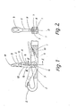
- the latch needle shown in various embodiments in the drawing has a needle shaft 1 with a needle hook 2 arranged at the end.
- a longitudinal needle slot 3 which is provided with an opening 4 leading to the lower edge of the needle shaft and in which a needle tongue 5 is pivotably supported in an undamped manner about a tongue axis 6.
- the tongue axis 6 is formed by two bearing pins 7 pressed out of the shaft cheeks laterally delimiting the longitudinal needle slot 3, on which the needle tongue 5 is mounted by means of a bearing bore 8.
- the needle tongue 5 carries at one end a spoon 9 with which it covers the tip of the needle hook 2 in the closed position.
- the needle tongue 5 is provided with at least one continuous recess in all the illustrated embodiments:
- a continuous, elongated, slot-like recess 11 is provided in the needle tongue 5 in the specified area, which is wider in the vicinity of the bearing bore 8 than in the vicinity of the spoon 9 and therefore with the neighboring ones Side faces 12 of the webs 13, which are approximately wedge-shaped in the side view, delimitate thin webs 13 which are connected at the ends by the material of the needle tongue 5 and which in turn produce a connection between the part of the needle tongue 5 containing the bearing bore 8 and its spoon 9.
- the continuous, elongated recess 11 not only causes a reduction in the inert mass of the needle tongue 5, but also results in a favorable dynamic bending behavior of the needle tongue.
- FIGS. 3, 4 essentially corresponds to that according to FIGS. 1, 2.
- the same parts are therefore again provided with the same reference numerals; they require no further explanation.
- the needle tongue 5 ver.
- the circular recesses 19 can have the same diameter; their diameter can also progressively decrease from the bearing bore 8 to the spoon 9.
- the recesses 19 can also be designed differently, for example elongated, instead of the cross-sectional shape shown; it is also conceivable not to arrange them in a row with their axes in the common plane 18, but to distribute them over the associated side surfaces of the needle tongue 5.
Landscapes
- Engineering & Computer Science (AREA)
- Textile Engineering (AREA)
- Knitting Machines (AREA)
Applications Claiming Priority (2)
| Application Number | Priority Date | Filing Date | Title |
|---|---|---|---|
| DE3331031A DE3331031C2 (de) | 1983-08-27 | 1983-08-27 | Zungennadel für maschenbildende Textilmaschinen |
| DE3331031 | 1983-08-27 |
Publications (3)
| Publication Number | Publication Date |
|---|---|
| EP0149701A2 true EP0149701A2 (fr) | 1985-07-31 |
| EP0149701A3 EP0149701A3 (en) | 1986-10-08 |
| EP0149701B1 EP0149701B1 (fr) | 1988-08-10 |
Family
ID=6207661
Family Applications (1)
| Application Number | Title | Priority Date | Filing Date |
|---|---|---|---|
| EP84105617A Expired EP0149701B1 (fr) | 1983-08-27 | 1984-05-17 | Aiguille à clapet pour les machines textiles formant des mailles |
Country Status (5)
| Country | Link |
|---|---|
| US (1) | US4601180A (fr) |
| EP (1) | EP0149701B1 (fr) |
| JP (1) | JPS6071750A (fr) |
| KR (1) | KR860000951B1 (fr) |
| DE (2) | DE3331031C2 (fr) |
Families Citing this family (6)
| Publication number | Priority date | Publication date | Assignee | Title |
|---|---|---|---|---|
| DE8706529U1 (de) * | 1987-05-07 | 1987-06-19 | Theodor Groz & Söhne & Ernst Beckert Nadelfabrik KG, 7470 Albstadt | Zungennadel für maschenbildende Textilmaschinen |
| DE19512375C1 (de) * | 1995-04-01 | 1996-06-20 | Groz & Soehne Theodor | Zungennadel für Maschinen zur Herstellung von Maschenware |
| EP1584722B1 (fr) * | 2004-04-06 | 2007-04-18 | Groz-Beckert KG | Aiguille à clapet pour une machine textile formant des mailles |
| EP1870502B1 (fr) * | 2006-06-21 | 2009-07-29 | Groz-Beckert KG | Aiguille à clapet pour machine textile formant des mailles |
| EP2088228B1 (fr) * | 2008-02-05 | 2011-10-19 | Groz-Beckert KG | Aiguille à clapet |
| EP2224048B1 (fr) * | 2009-02-26 | 2011-08-31 | Groz-Beckert KG | Aiguille à clapet dotée d'une goupille axiale rotative |
Family Cites Families (7)
| Publication number | Priority date | Publication date | Assignee | Title |
|---|---|---|---|---|
| US2596311A (en) * | 1945-02-15 | 1952-05-13 | American Vitos Company Inc | Knitting needle |
| US3031867A (en) * | 1958-07-28 | 1962-05-01 | Groz & Soehne Theodor | Latch needle for knitting machines or the like |
| US3728874A (en) * | 1971-08-19 | 1973-04-24 | Torrington Co | Straddle latch needle |
| DE7640654U1 (de) * | 1976-12-24 | 1977-04-21 | Theodor Groz & Soehne & Ernst Beckert Nadelfabrik Kg, 7470 Albstadt | Zungennadel fuer strickmaschinen |
| DE2714607C3 (de) * | 1977-04-01 | 1983-12-08 | Theodor Groz & Söhne & Ernst Beckert Nadelfabrik KG, 7470 Albstadt | Zungennadel für Maschinen zur Herstellung von Maschenware |
| DE3014751C2 (de) * | 1980-04-17 | 1982-06-16 | Theodor Groz & Söhne & Ernst Beckert Nadelfabrik KG, 7470 Albstadt | Gestanztes Strickwerkzeug für Strick- oder Wirkmaschinen |
| JPS6322931A (ja) | 1986-07-16 | 1988-01-30 | 株式会社イナックス | 小便器の洗浄方法及び装置 |
-
1983
- 1983-08-27 DE DE3331031A patent/DE3331031C2/de not_active Expired
-
1984
- 1984-05-17 EP EP84105617A patent/EP0149701B1/fr not_active Expired
- 1984-05-17 DE DE8484105617T patent/DE3473309D1/de not_active Expired
- 1984-08-24 KR KR1019840005146A patent/KR860000951B1/ko not_active Expired
- 1984-08-27 JP JP59178172A patent/JPS6071750A/ja active Granted
-
1985
- 1985-12-09 US US06/807,763 patent/US4601180A/en not_active Expired - Fee Related
Also Published As
| Publication number | Publication date |
|---|---|
| JPS6125823B2 (fr) | 1986-06-17 |
| EP0149701A3 (en) | 1986-10-08 |
| JPS6071750A (ja) | 1985-04-23 |
| DE3331031C2 (de) | 1985-07-11 |
| US4601180A (en) | 1986-07-22 |
| DE3331031A1 (de) | 1985-03-14 |
| KR860000951B1 (ko) | 1986-07-23 |
| DE3473309D1 (en) | 1988-09-15 |
| KR850002496A (ko) | 1985-05-13 |
| EP0149701B1 (fr) | 1988-08-10 |
Similar Documents
| Publication | Publication Date | Title |
|---|---|---|
| DE7819327U1 (de) | Nadelmodul fuer eine tuftingmaschine | |
| EP0149701B1 (fr) | Aiguille à clapet pour les machines textiles formant des mailles | |
| EP1500733B1 (fr) | Aiguille pour machine à tricoter | |
| DE102006004098B3 (de) | Barre einer Wirkmaschine | |
| EP0375843B1 (fr) | Outil de tricotage étampé pour des machines textiles notamment pour des machines à tricoter | |
| EP0290805B1 (fr) | Outil à tricoter étampé pour des machines textiles, notamment pour des machines à tricoter | |
| DE102006004099B3 (de) | Wirkelement, insbesondere Wirknadel einer Kettenwirkmaschine, sowie Wirkmaschinen-Barre | |
| EP0123914B1 (fr) | Outil de tricotage étampé pour métier à tricoter | |
| EP1241287B1 (fr) | Elément constructif | |
| DE3921506C1 (fr) | ||
| DE2610078C3 (de) | Zungennadel für Strickmaschinen | |
| DE3105358C2 (fr) | ||
| DE3600621C1 (de) | Zungennadel fuer Textilmaschinen | |
| DE3331030C1 (de) | Zungennadel fuer Maschinen zur Herstellung von Maschenware | |
| DE3022172A1 (de) | Fadenwaechter fuer wirkstuehle | |
| EP0735174B1 (fr) | Aiguille à clapet pour des machines de fabrication de tricot | |
| DE102010044673B4 (de) | Wirkwerkzeugbarren-Reparaturset und Wirkwerkzeugbarre | |
| DE4324232C2 (de) | Zungennadel für Maschinen zur Herstellung von Maschenware | |
| EP3597807B1 (fr) | Outil de machine à tricoter, en particulier aiguille à tricoter de machine à tricoter | |
| EP0647733B1 (fr) | Aiguille à clapet pour des machines textiles | |
| DE20010219U1 (de) | Fadenführer | |
| EP0029114A1 (fr) | Dispositif de fixation d'une barrette porte-aiguilles dans des machines porteuses de barrettes d'aiguilles | |
| DE102018127475B4 (de) | Bremsbelaghalterung für ein Schienenfahrzeug | |
| DE1184566B (de) | Mit lamellenartig ineinandergreifenden Laschenkoerpern versehene Metallgliederkette mit ueber die ganze Kettenbreite durchgehenden Wiegegelenken | |
| DE1750824C3 (de) | Raupenketten-Verbindungsglied |
Legal Events
| Date | Code | Title | Description |
|---|---|---|---|
| PUAI | Public reference made under article 153(3) epc to a published international application that has entered the european phase |
Free format text: ORIGINAL CODE: 0009012 |
|
| AK | Designated contracting states |
Designated state(s): CH DE FR GB IT LI |
|
| PUAL | Search report despatched |
Free format text: ORIGINAL CODE: 0009013 |
|
| AK | Designated contracting states |
Kind code of ref document: A3 Designated state(s): CH DE FR GB IT LI |
|
| 17P | Request for examination filed |
Effective date: 19870311 |
|
| 17Q | First examination report despatched |
Effective date: 19870624 |
|
| GRAA | (expected) grant |
Free format text: ORIGINAL CODE: 0009210 |
|
| AK | Designated contracting states |
Kind code of ref document: B1 Designated state(s): CH DE FR GB IT LI |
|
| PG25 | Lapsed in a contracting state [announced via postgrant information from national office to epo] |
Ref country code: IT Free format text: LAPSE BECAUSE OF FAILURE TO SUBMIT A TRANSLATION OF THE DESCRIPTION OR TO PAY THE FEE WITHIN THE PRESCRIBED TIME-LIMIT;WARNING: LAPSES OF ITALIAN PATENTS WITH EFFECTIVE DATE BEFORE 2007 MAY HAVE OCCURRED AT ANY TIME BEFORE 2007. THE CORRECT EFFECTIVE DATE MAY BE DIFFERENT FROM THE ONE RECORDED. Effective date: 19880810 Ref country code: GB Free format text: LAPSE BECAUSE OF NON-PAYMENT OF DUE FEES Effective date: 19880810 Ref country code: FR Free format text: THE PATENT HAS BEEN ANNULLED BY A DECISION OF A NATIONAL AUTHORITY Effective date: 19880810 |
|
| REF | Corresponds to: |
Ref document number: 3473309 Country of ref document: DE Date of ref document: 19880915 |
|
| EN | Fr: translation not filed | ||
| GBV | Gb: ep patent (uk) treated as always having been void in accordance with gb section 77(7)/1977 [no translation filed] | ||
| PG25 | Lapsed in a contracting state [announced via postgrant information from national office to epo] |
Ref country code: LI Effective date: 19890531 Ref country code: CH Effective date: 19890531 |
|
| PLBE | No opposition filed within time limit |
Free format text: ORIGINAL CODE: 0009261 |
|
| STAA | Information on the status of an ep patent application or granted ep patent |
Free format text: STATUS: NO OPPOSITION FILED WITHIN TIME LIMIT |
|
| 26N | No opposition filed | ||
| REG | Reference to a national code |
Ref country code: CH Ref legal event code: PL |
|
| PG25 | Lapsed in a contracting state [announced via postgrant information from national office to epo] |
Ref country code: DE Effective date: 19900201 |