EP0149738A2 - Machine et procédé de fabrication d'un récipient d'emballage en tôle - Google Patents
Machine et procédé de fabrication d'un récipient d'emballage en tôle Download PDFInfo
- Publication number
- EP0149738A2 EP0149738A2 EP84113248A EP84113248A EP0149738A2 EP 0149738 A2 EP0149738 A2 EP 0149738A2 EP 84113248 A EP84113248 A EP 84113248A EP 84113248 A EP84113248 A EP 84113248A EP 0149738 A2 EP0149738 A2 EP 0149738A2
- Authority
- EP
- European Patent Office
- Prior art keywords
- fold
- machine according
- head
- counter
- cover
- Prior art date
- Legal status (The legal status is an assumption and is not a legal conclusion. Google has not performed a legal analysis and makes no representation as to the accuracy of the status listed.)
- Withdrawn
Links
- 239000002184 metal Substances 0.000 title claims abstract description 7
- 238000004519 manufacturing process Methods 0.000 title claims description 4
- 238000012856 packing Methods 0.000 title abstract 2
- 238000004806 packaging method and process Methods 0.000 claims description 102
- 238000007654 immersion Methods 0.000 claims description 58
- 238000003780 insertion Methods 0.000 claims description 37
- 230000037431 insertion Effects 0.000 claims description 37
- 238000007789 sealing Methods 0.000 claims description 32
- 239000012530 fluid Substances 0.000 claims description 24
- 238000012546 transfer Methods 0.000 claims description 16
- 238000007373 indentation Methods 0.000 claims description 8
- 238000006073 displacement reaction Methods 0.000 claims description 2
- 239000007921 spray Substances 0.000 claims 2
- 230000006835 compression Effects 0.000 abstract 1
- 238000007906 compression Methods 0.000 abstract 1
- 230000000295 complement effect Effects 0.000 description 10
- 238000000034 method Methods 0.000 description 5
- 230000009471 action Effects 0.000 description 4
- 230000007246 mechanism Effects 0.000 description 3
- 230000008569 process Effects 0.000 description 3
- 238000010276 construction Methods 0.000 description 2
- 238000013461 design Methods 0.000 description 2
- 238000007598 dipping method Methods 0.000 description 2
- 238000005096 rolling process Methods 0.000 description 2
- 238000000926 separation method Methods 0.000 description 2
- 229910000831 Steel Inorganic materials 0.000 description 1
- 230000000903 blocking effect Effects 0.000 description 1
- 230000008859 change Effects 0.000 description 1
- 238000005352 clarification Methods 0.000 description 1
- 150000001875 compounds Chemical class 0.000 description 1
- 230000009189 diving Effects 0.000 description 1
- 210000003746 feather Anatomy 0.000 description 1
- 239000003292 glue Substances 0.000 description 1
- 238000002347 injection Methods 0.000 description 1
- 239000007924 injection Substances 0.000 description 1
- 239000000463 material Substances 0.000 description 1
- 238000011022 operating instruction Methods 0.000 description 1
- 238000003825 pressing Methods 0.000 description 1
- 238000012545 processing Methods 0.000 description 1
- 238000007493 shaping process Methods 0.000 description 1
- 239000010959 steel Substances 0.000 description 1
- 230000007704 transition Effects 0.000 description 1
Images







Classifications
-
- B—PERFORMING OPERATIONS; TRANSPORTING
- B65—CONVEYING; PACKING; STORING; HANDLING THIN OR FILAMENTARY MATERIAL
- B65D—CONTAINERS FOR STORAGE OR TRANSPORT OF ARTICLES OR MATERIALS, e.g. BAGS, BARRELS, BOTTLES, BOXES, CANS, CARTONS, CRATES, DRUMS, JARS, TANKS, HOPPERS, FORWARDING CONTAINERS; ACCESSORIES, CLOSURES, OR FITTINGS THEREFOR; PACKAGING ELEMENTS; PACKAGES
- B65D83/00—Containers or packages with special means for dispensing contents
- B65D83/14—Containers for dispensing liquid or semi-liquid contents by internal gaseous pressure, i.e. aerosol containers comprising propellant
- B65D83/38—Details of the container body
-
- B—PERFORMING OPERATIONS; TRANSPORTING
- B21—MECHANICAL METAL-WORKING WITHOUT ESSENTIALLY REMOVING MATERIAL; PUNCHING METAL
- B21D—WORKING OR PROCESSING OF SHEET METAL OR METAL TUBES, RODS OR PROFILES WITHOUT ESSENTIALLY REMOVING MATERIAL; PUNCHING METAL
- B21D51/00—Making hollow objects
- B21D51/16—Making hollow objects characterised by the use of the objects
- B21D51/26—Making hollow objects characterised by the use of the objects cans or tins; Closing same in a permanent manner
- B21D51/30—Folding the circumferential seam
- B21D51/32—Folding the circumferential seam by rolling
Definitions
- the invention relates to a machine according to the preamble of claim 1.
- round can bodies can be flanged on both sides by upsetting heads in a first work station and a floor in a second work station standing can be folded open.
- the floor is folded up with two pre-rolls and two post-rolls or finished rolls.
- the invention has for its object to provide a machine for turning the folds and / or folding the fuselage folds and / or dipping the fuselage folds and to provide a method for dipping.
- Steel sheet is particularly suitable as the sheet for the packaging container.
- the stroke of the relative axial movement is preferably adjustable.
- Both the insertion head and the counter-holder can be axially movable in each case. This facilitates and speeds up the transport of the packaging container into and out of the inlaying station.
- a securely centered support of the packaging container is guaranteed. Additional support on the trunk shoulder can take place when the adjacent fold is drawn in with respect to the trunk.
- the features of claim 6 enable the processed packaging container to be ejected with little construction effort.
- a defined axial end position of the ejection piston and thus of the packaging container is reached. Ejection can also be accomplished with simple means according to claim 8.
- the springs are preferably evenly distributed over the circumference.
- the transfer station according to claim 15 is simple and robust.
- ejection is made possible with simple and reliable means.
- the ejection piston is expediently secured against rotation relative to the counter-holding sleeve.
- a large-area contact of the counter-holding head with the bottom region of the packaging container and thus securing the packaging container against rotating entrainment by the transfer head can pass.
- the features of claim 20 offer a safe ejection of the packaging container with little construction.
- the rollers according to claim 21 are preferably moved radially with respect to the packaging container in and out of contact with the hull fold.
- the roles are e.g. are stored in roller bearings and are rotated about their own longitudinal axis by friction on the packaging container.
- the packaging container stands still, so it preferably does not rotate along its longitudinal axis. Rather, the rollers run around the packaging container.
- the pre-rolling and finished rolling according to claim 22 protects the material of the hull fold and leads to a gentle, wrinkle-free folding of the hull fold.
- the friction surface preventing an unwanted rotation of the packaging container during the folding is increased.
- the features of claim 25 support a gentle and precise folding of the hull fold.
- the immersion leads to a further considerable increase in strength and thus operational safety on the finished packaging container.
- the immersion station according to claim 29 is structurally simple and reliable.
- the features of claim 30 allow the interior of the packaging container during the injection of the diving Rum p ffalte to be kept under overpressure.
- This overpressure can, for example, be of the order of magnitude of an operating pressure that will later prevail in the ready-to-use packaging container.
- the aim of the internal overpressure is to prevent further inversion or other undesirable deformation of the base area during the immersion.
- the internal overpressure acts practically as an omnipresent counterhold against the immersion stress. Compressed air is particularly suitable as the pressure fluid.
- the packaging container can be fixed quickly and safely in the axial direction before the internal excess pressure is built up.
- the ejection is solved in a simple and reliable manner.
- the features of claim 33 lead to the fact that the packaging container is first brought to the sealing ring with its mouth in the sealing system, the internal overpressure is built up and only then is the immersion started.
- the immersion is also solved for the lid-side hull fold.
- the features of claim 35 allow the bottom-side ejection of the packaging container in a simple and reliable manner.
- an internal overpressure can be built up in the packaging container even before the lid-side hull folds are immersed.
- a seal between the sealing member and the mouth of the packaging container is reliably accomplished in a simple manner.
- the actuating element can also be used to guide the pressure fluid.
- the features of claim 40 offer secure guidance of the ejection ring and the packaging container as long as it is immersed in the guide sleeve.
- the immersion station according to claim 42 enables particularly high production speeds when the bottom-side and the lid-side hull folds are to be immersed.
- the above-mentioned object is also achieved with regard to immersion by the method features of claim 43.
- the overpressure in the interior of the packaging container during immersion provides an internal counterforce which effectively prevents an undesirable change in shape of the packaging container and in particular the surroundings of the body fold to be immersed.
- FIG. 1 shows a machine 1, to which prefabricated packaging containers 2 are fed in a manner known per se and not shown.
- the packaging containers 2 are received in a loading station 3 (FIG. 2) by transport stars 4 and 5 arranged at an axial distance from one another, each in a circumferential recess 6 when the transport stars 4, 5 are stationary.
- the transport stars 4, 5 are then rotated by a division of 72 ° according to FIG. 2 in the direction of an arrow 7.
- the packaging container 2 introduced in the charging station 3 arrives in an insertion station 8 for a bottom fold 35 of the packaging container 2. Only this position of the packaging container 2 is shown in FIGS. 1 and 2 for simplification of the drawing.
- the transport stars 4, 5 are rotated by a further division of 72 ° in the direction of the arrow 7 until the packaging container 2 arrives at the folding station 8 into a transfer station 10 for a bottom-side hull fold of the packaging container 2. There the transport stars 4, 5 are brought to a standstill again and the work step in question is carried out. After this step, the transport stars 4, 5 are rotated further in the direction of arrow 7, so that in the transfer station 10 treated packaging containers 2 reach an immersion station 11 for the bottom-side hull fold where the associated work step is carried out. After this latter step has been completed, the transport stars 4, 5 are again rotated by 72 ° in the direction of the arrow 7 until the packaging container 2 treated in the immersion station 11 arrives in a removal station 12, where it is removed from the machine 1.
- a packaging container 2 is handled or processed essentially simultaneously in each of the stations 3, 8, 10, 11 and 12.
- a guide rail 13 coaxial with the transport stars 4, 5 holds the packaging containers 2 as they circulate in the circumferential recesses 6 of the transport stars 4, 5.
- a counter-holder 14 and a push-in head 15 are each movable in the axial direction relative to one another by a toggle lever mechanism 16 and 17.
- a counter-holder 18 by means not shown, e.g. again a toggle lever mechanism, movable in the axial direction relative to an axially stationary transfer head 19.
- a holding device 20 and an immersion head 21 are each axially movable relative to one another by means not shown.
- the counter-holder 14 is fastened by screws 22 to a flange 23 of the machine 1.
- the counter-holder 14 has a counter-holding sleeve 26 which supports the adjacent cover fold 24 and a radially outwardly projecting trunk shoulder 25 of the packaging container 2 which adjoins the cover fold 24.
- the counter-holding sleeve 26 is provided with three axial ones which are evenly distributed over the circumference and begin at the flange 23 Provided slots 27, in each of which a holding screw 28 is guided, which is screwed radially into an ejector piston 29 mounted axially displaceably in the counter-holding sleeve 26.
- the ejection piston 29 is biased by a spring 30 into an outer rest position shown in FIG. 3, in which the retaining screws 28 each abut a stop surface 31 of the counter-holding sleeve 26.
- the ejection piston 29 supports a curl or mouth 32 of a lid 33 of the packaging container.
- a body 34 of the packaging container 2 is tightly and firmly connected to the cover 33 via the cover fold 24 and to a bottom 36 of the packaging container 2 via a base fold 35 (FIG. 4).
- the insertion head 15 is fastened to a carrier 38 of the machine 1 with a central screw 37.
- the push-in head 15 is surrounded by an ejection ring 39 which is biased by a plurality of springs 40 distributed over its circumference in an outer rest position projecting axially to the left in FIG. 4 over the push-in head 15.
- This rest position is defined by retaining screws 41 distributed over the circumference, which on the one hand are screwed into the ejection ring 39 and on the other hand cooperate with their head with a stop surface 42 of the insertion head 15.
- the ejection ring 39 is shown in this outer rest position, in which it has just ejected the packaging container 2 and is still touching at the free end of a hull fold 43.
- the insertion station 8 functions as follows: At the beginning, the counter-holder 14 and the insertion head 15 are moved apart axially so far that a packaging container 2 inserted into the machine 1 in the loading station (FIG. 2) is just its length fits in between. In this condition, the floor is the same area of the packaging container 2 the lid area shown in FIG. 3.
- the bottom rebate 35 is thus located like the top rebate 24 outside the trunk 34, a trunk shoulder corresponding to the trunk shoulder 25 producing the transition between the trunk 34 and the bottom rebate 35. Originally, the bottom rebate 35 was also drawn in relative to the fuselage 34 ("necked in").
- the ejection ring 39 with its left inner edge is first brought into contact with the fuselage shoulder glue which no longer exists in FIG. 4 and corresponds to the fuselage shoulder 25.
- This trunk shoulder ends the movement of the ejection ring 39 to the left.
- the push-in head 15 continues to move to the left in FIG. 4 under increasing tension of the springs 40, until it comes into contact with the bottom fold 35 and with a rounded edge 47 with the outside of the bottom 36 substantially simultaneously.
- the bottom 36 with the bottom fold 35 is then increasingly turned inside the fuselage 34. This creates the hull fold 43 on the bottom.
- the counter-holder 14 and the insertion head 15 are moved apart again synchronously.
- the ejection piston 29 takes over the separation of the packaging container 2 from the counter-holding sleeve 26 and the ejection ring 39 separates the packaging container 2 from the insertion head 15 until, shortly after the position shown in FIGS. 3 and 4, the packaging container 2 completely in the axial direction is released for further transport through the transport stars 4, 5 into the transfer station 10 (FIGS. 1 and 2).
- Fig. 5 shows in dash-dotted lines the insertion head 15 in its axial end position in which the hull fold 43 is completed.
- the gaps between the individual sheet layers according to FIG. 5 normally do not exist in reality. They are only intended to clarify the graphic representation.
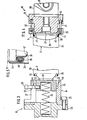
- the counter-holder 18 has a counter-holding sleeve 48 which is fastened to a flange 50 of the machine 1 (FIG. 1) with screws 49.
- the counter sleeve 48 supports the cover fold 24 with a shoulder 51 and an outer ring zone of the cover 33 with a contour 52 complementary to the cover 33 when these parts have come into contact with one another.
- An ejection piston 53 is axially displaceably mounted in the counter-holding sleeve 48, which is biased by a spring 54 into an outer rest position shown in FIG. 6 and supports the mouth 32 of the packaging container 2 on the outside.
- a radial extension 55 of the Auswerfkolbens 53 slides in an axial groove 56 of the Ge g enhaltehülse 48 and prevents relative rotation of the Auswerfkolbens 53 and the counter-holding sleeve 48th
- the folding head 19 has a stationary, non-rotating support stamp 57, which comes to achieve the largest possible contact with the floor 36 is complementary to the outer surface of the bottom 36.
- an ejection die 58 which can be controlled by the machine 1 is axially displaceably mounted and can be pushed out into an outer ejection position which projects out on the support die 57.
- the inner or rest position of the ejecting die 58 is shown, in which it supports the center of the base 36 with its free end which is complementary to the base 36.
- the transfer head 19 also has two diametrically opposite preliminary rollers 59 and two finished rollers 60 which are offset by 90 ° relative to the preliminary rollers 59.
- Fig. 7 only a pre-roll 59 and a finished roll 60 offset by 90 ° is shown.
- the rollers 59, 60 are each freely rotatable with roller bearings, not shown, mounted on an axis 61 and 62 such that their longitudinal axes 63 and 64 run parallel to the longitudinal axis 65 of the packaging container 2.
- the transfer station 10 functions as follows: First, the counter-holder 18 has been moved to the left so far that the packaging container 2 arriving in the transport stars 4, 5 can reach the counter-holder 18 and the transfer head 19 without contact. When it has reached its axially aligned position there, the counter-holder 18 is moved to the right in FIG. 6 until the ejection piston 53 touches the mouth 32. From this moment on, the packaging container 2 is shifted to the right in the direction of its longitudinal axis 65 in FIGS. 6 and 7. This usually happens without the ejection piston 53 moving relative to the counter-holding sleeve 48.
- the rollers 59, 60 are located at a radial distance from the fuselage 34 and the bottom fuselage fold 43, which is designed according to FIG. 5 and extends in the axial direction.
- the axes 61, 62 with the rollers 59, 60 run around the stationary one Packaging container 2 um.
- the two preliminary rollers 59 are first moved synchronously radially inward until they come into contact with the convex fold 43 according to FIG. 5 with a convexly curved contact surface 66 and this continues as the radially inward movement continues up to the one in FIG. 7 above see intermediate position indicated by dash-dotted lines in FIG. 8. 7, the preliminary roller 59 is drawn in its inward radial end position.
- the two finished rolls 60 are also moved synchronously radially inwards until they come into contact with the convexly curved contact surfaces 66 with the partly folded hull fold 43 and the free end thereof points essentially radially inwards finally kill.
- This state of the fuselage fold 43 is shown at the bottom in FIG. 7 and in full lines in FIG. 8. 7, the finished roll 60 has its inner radial end position reached.
- the rollers 59, 60 are moved radially outward into their starting position and the counter-holder 18 and the ejecting punch 58 in FIGS. 6 and 7 are moved to the left until the packaging container 2 returns to its transport position in the Transport stars 4, 5 has taken.
- the packaging container 2 comes free from the support stamp 57 because the outer diameter of the support stamp 57 is smaller than the inner diameter of the free end of the fully folded hull fold 43.
- the ejection punch 58 is then moved back into its starting position shown in FIG. 7 by the machine control.
- the contact surface 66 of the preliminary roller 59 merges into an inward folding surface 67 which encloses a relatively small angle 69 with a radial plane 68.
- the folding surface 67 merges inward into an axial recess 70 of the preliminary roller 59.
- the finished rolls 60 are designed in the same way as the preliminary rolls 59.
- the immersion station 11 has a holding device 71 for holding the hull fold 43 (FIG. 8) on the bottom side.
- the holding device 71 can be moved back and forth in the direction of the longitudinal axis 65 of the packaging container 2 by known drive means of the machine 1 (FIG. 1).
- an ejection piston 73 is mounted axially displaceably, which is biased by an spring 74 supported on the carrier 72 into an outer rest position to the right in FIG. 10 and on the outside with a sealing ring 75, e.g. made of rubber, the mouth 32 of the packaging container 2 supports.
- each locking element 77 can be driven synchronously back and forth by a double-acting piston-cylinder unit 78, which are each fastened to the carrier 72 with screws 80 by means of a bracket 79.
- the sealing ring 75 is fastened to the ejection piston 73 with a central screw 81.
- a pressure fluid channel 82 is formed in the screw 81 and the ejection piston 83 and has a connection to the outside via a connecting piece 83.
- the connecting piece 83 can be connected via a line 84 and a 3-way / 2 position valve 85 to a pressure fluid source 86, in this case a compressed air source.
- the directional control valve 85 is controlled by the movement of the holding device 71 in the direction of the longitudinal axis 65.
- An axial slot 87 is formed in the carrier 72 in the range of movement of the connecting piece 83.
- the outer rest position of the ejection piston 73 is defined by the contact of a ring 88 of the ejection piston 73 on a stop surface 89 of the carrier 72.
- the immersion station 11 has an immersion head 90 which can be moved back and forth with a flange 91 and screws 92 on a carrier which can be moved back and forth in the direction of the longitudinal axis 65 of the packaging container 2 by a drive of the machine 1 (FIG. 1) which is known per se 93 of the machine 1 is attached.
- a guide sleeve 95 is fastened to the flange 91 with screws 94 outside the annular immersion head 90, in which a guide ring 96, which is in sliding contact with the immersion head 90, is axially displaceably guided.
- the ejector ring 96 is, by means of springs 97 distributed over the circumference, in an axially above the immersion head 90 protruding, outer rest position biased and supports a radially outer area of the hull fold 43 on the outside.
- the guide sleeve 95 can also take over the radial guidance of the body 34 of the packaging container 2 when the bottom end of the body dips into the guide sleeve 95.
- the immersion head 90 has a convexly curved contact surface 98 which first comes into contact with a radially inner region of the folded-over hull fold 43 (FIG. 8).
- FIG. 12 shows the immersion head 90 in its axial end position which has penetrated the deepest into the packaging container 2.
- the hull fold 43 essentially has its submerged final shape.
- the air shown in FIG. 12 for clarification between the individual sheet metal layers either in the area of the bottom fold 35 and in the area of the hull fold 43 will either not be present in practice or only to an extremely small extent.
- a sealing compound is used in a manner known per se, which ensures the desired tightness of the rebate connections.
- the immersion station 11 functions as follows: At the beginning of the work cycle, the holding device 71 (FIG. 10) and the assembly according to FIG. 11 having the immersion head 90 are moved apart axially so far that the packaging container to be processed 2 can easily be brought into the processing position by the transport stars 4, 5. The holding device 71 and the assembly according to FIG. 11 are then moved together axially. The folded hull folds 43 (FIG. 8) lie against the ejector ring 96 and the mouth 32 against the sealing ring 75.
- the force of the spring 74 (FIG. 10) is set lower than the sum of the forces of the springs 97 (FIG. 11).
- the packaging container 2 increasingly displaces the ejection piston 73 (FIG. 10) while compressing the spring 74 into the end position shown in FIG. 10 in contact with the carrier 72 as the axial relative movement continues.
- the mouth 32 is pressed into a sufficient sealing system on the sealing ring 75.
- the two locking elements 77 have been in their radially outer rest position.
- the piston-cylinder units 78 are actuated until the locking elements 77 have moved into their operating position shown in FIG. 10, in which they are positively locked with the outer area of the trunk shoulder 25 and the lid fold 24 and thereby the packaging container 2 in hold the axial relative position to the holding device 71 in which the mouth 32 is sealed with respect to the sealing ring 75.
- the directional control valve 85 is switched through to the position shown in FIG. 10, in which the pressure fluid source 86 is connected to the pressure fluid channel 82 and thus to the interior of the packaging container 2.
- the holding device 71 and the assembly according to FIG. 11 continue to move axially towards one another.
- the packaging container 2 is increasingly immersed in the guide sleeve 95 and thereby tensioning the springs 97.
- the contact surface 98 of the immersion head 90 comes into contact with the folded-over hull fold 43 (FIG. 8) when the internal pressure is fully developed inside the packaging container 2 and compresses the torso fold 43 increasingly in the plunged end position shown in FIGS. 11 and 12.
- the holding device 71 and the assembly according to FIG. 11 are then moved axially apart again, where 11 due to the dominance of the springs 97 via the spring 74, the ejection position shown in FIG. 11 is obtained before the locking elements 77 are retracted radially outwards in FIG. 10 and allow the ejection piston 73 to move outward under the action of its spring 74.
- the directional valve 85 has been switched through to the other switching position by the axial opening movement of the holding device 71, which ventilates the inside of the packaging container 2 via the pressure fluid channel 82.
- the ring 88 finally abuts the stop surface 89 of the carrier 72, the packaging container 2 is again in the axial position relative to the machine 1 (FIG. 1) in which it has arrived with the transport stars 4, 5 and to the removal station 12 ( Fig. 2) is to be passed on.
- the machine 1 according to FIG. 1 can also be equipped with stations that have the same structure and that allow the insertion, folding and immersion on the lid side of the packaging container 2.
- a machine equipped in this way can, in concatenation with the machine according to FIG. 1, take over the packaging containers 2 removed from the removal station 12 of the machine 1 and further process them on the cover side.
- FIGS. 3 and 4 show an indentation station 99 for the lid fold 24, the same parts as in FIGS. 3 and 4 being provided with the same reference numbers.
- a packaging container 2 which was previously processed in the immersion station 11 according to FIGS. 10 and 11, is processed further. Therefore, in FIG. 13, the immersed fuselage fold 43 on the bottom rests against an outer flange 100 of the ejection piston 29, which in each working cycle against the force of the spring 30 against a stop surface 101 of the Counter sleeve 26 is driven. If, instead, a packaging container 2 is to be processed in the turning-in station 99, the bottom fold 35 of which has not yet been pushed in according to FIG. 5, the counter-holding sleeve 26 expediently has seating surfaces corresponding to the seat surfaces 44, 45 in FIG. 3 for the bottom fold 35 and the adjoining one Trunk shoulder on.
- the ejection piston 29 would be designed on its side facing the packaging container 2 to be complementary to the outer surface of the base 36 and / or the flange 100 should be reduced in diameter to such an extent that it would only touch a radially inner region of the base fold 35.
- an ejection piston 102 is axially displaceably mounted in the insertion head 15.
- the ejection piston 102 is biased by a spring 103 into an outer rest position defined by a stop surface 104 of the insertion head 15, which is shown in FIG. 14.
- the ejection piston 102 supports the mouth 32 of the packaging container 2.
- the insertion head 15 is provided on the outside with a shoulder 105 and then on the inside with a pressing surface 106 which is complementary to an outer region of the cover 33 and which offers a particularly large and secure support of the cover 33 and the cover fold 24 during the insertion.
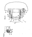
- FIGS. 15 and 16 show a folding station 108 for the fuselage fold 107 on the cover side.
- the basic structure and the mode of operation of the folding station 108 correspond to the folding station 10 according to FIGS. 6 and 7.
- the same parts are here again provided with the same reference numbers.
- FIG. 15 shows a counterholder 109 which supports the base region of the packaging container 2 and has a counterhold 110 which supports the base 36 and an inner ring zone of the fuselage fold 43 which is immersed in accordance with FIG.
- the complementary design of the counter-holding head 110 to the bottom 36 results in a particularly large mutual contact, which prevents the packaging container 2 from rotating along its longitudinal axis 65 under the action of the rollers 59, 60 (FIG. 16).
- the counter-holding head 110 is designed to be complementary to the bottom area of the packaging container 2 offered in each case.
- the counter-holding head 110 is surrounded by an ejection ring 111 which is biased by springs 112 distributed over the circumference into an outer rest position projecting axially beyond the counter-holding head 110 and which supports an outer ring zone of the bottom fuselage fold 43 on the outside.
- This outer rest position is defined by retaining screws 113 distributed over the circumference, which are screwed into the ejection ring 111 and rest in the rest position with their heads against a stop surface 114 of the counter-holding head 110.
- the support stamp 57 is in this case complementary to a central ring zone of the cover 33, and the ejection stamp 58 supports the mouth 32 of the packaging container 2.
- the function of the transfer station 108 corresponds to that of the transfer station 10 (FIGS. 6 and 7).
- FIG. 17 to 19 show an immersion station 115 for the lid-side fuselage folds 107 folded over in the transfer station 108 corresponding to FIG. 8.
- the same parts as in the immersion station 11 are provided with the same reference numbers.
- the pressure fluid channel 82 is defined by a tubular actuating element 116, which penetrates the ejection piston 73 lengthways and looks out of both ends of the ejection piston 73.
- the actuating element 116 is axially displaceable relative to the ejection piston 73 and, with its left end in FIG. 17, also penetrates a sealing member 117, for example a sealing plug, e.g. made of rubber.
- the actuating element 116 lies on the outside with a pressure plate 118 on the sealing member 117.
- a cross member 119 is fastened to the right end of the actuating element 116 in FIG. 17, with which a piston rod 120 of a piston-cylinder unit 121, which is arranged parallel to the longitudinal axis 65, is screwed.
- the cylinder 122 of the piston-cylinder unit 121 is fastened by a nut 123 to a crossmember 124, which in turn is fixed to the ejection piston 73 with a threaded pin 125.
- the double-acting piston-cylinder unit 121 is connected by lines 126 and 127 to a 4-way / 3-position valve 128, which is connected to a pressure fluid source 129.
- the ejection piston 73 is secured against rotation about its longitudinal axis by a feather key 131 which is displaceable in an axial groove 130 of the carrier 93.
- FIG. 18 shows the state in which the line 127 according to FIG. 17 is connected to the pressure fluid source 129 or the directional control valve 128 is subsequently in its middle, blocking switching position. Then, compared to FIG. 17, the actuating element 116 is displaced to the left relative to the ejection piston 73 and the sealing member 117 is relaxed so far that there is a radial distance between the sealing member 117 and the mouth 32, which allows the sealing member 117 to be inserted unhindered into the mouth 32 or the removal of the sealing member 117 from the mouth 32 is permitted.
- a counterholder 133 of the immersion station 115 is fastened to the carrier 72 of the machine 1 (FIG. 1) by screws 134.
- the counter-holder 133 where the bottom-side fuselage fold 43 is already immersed, is complementary to the bottom 36 of the packaging container 2 in order to achieve a large-area support.
- the counter-holder is surrounded by an ejection ring 135, which is biased into an axially outer rest position by springs 136 distributed over the circumference and supports the fuselage fold 43 on the outside.
- the rest position is defined by a stop surface 137 of an outer guide sleeve 138, in which the ejection ring 135 is axially guided and which is fastened to the counter-holder 133 with screws 139.
- the immersion station 115 functions as follows: initially, the structural units shown in FIGS. 17 and 19 have moved apart axially to such an extent that the newly arriving packaging container 2 can be positioned between them without difficulty. 17 and 19 are then moved towards one another in the direction of the longitudinal axis 65. Since the sum of the forces of the springs 136 (FIG. 19) is greater than the sum of the forces of the springs 97 (FIG. 17), after the packaging container 2 has first come into contact with the ejection rings 96 and 135, the ejection ring 135 remains when the axial feed movement continues of the two structural units in its rest position shown in FIG.
- FIG. 17 This intermediate position corresponds to the relative arrangement of the parts according to FIG. 18.
- the axial feed movement of the structural units according to FIGS. 17 and 19 can be interrupted for a short time until, starting from the situation according to FIG. 18, after switching the directional valve 128 into 17, the actuating element 116 is drawn to the right relative to the ejection piston 73 and the sealing member 117 is thereby tensioned into the hermetically sealing position shown in FIG. 17.
- the delivery movement of the two structural units according to FIGS. 17 and 19 can then be continued while the interior of the packaging container 2 is placed under fluid pressure after actuation of the directional control valve 85 ′.
- the contact surface 98 of the immersion head 90 comes into contact with the cover-side fuselage fold 107, which at this moment occurs, when the delivery movement of the structural units continues 8 is also folded radially inward, as shown in FIG. 18.
- the fuselage 107 is then immersed by the plunge head 90 and its contact surface 98 from the folded position shown in FIG. 18 into the finished end position drawn in FIG. 17 and drawn around the lid fold 24. 17 and 19 are axially moved apart again until the intermediate position shown in FIG. 17 is reached.
- the directional control valve 85 ' has preferably been switched over and the pressure fluid supply has thereby been interrupted.
- the directional valve 128 is now switched through to the switching position in which the line 127 is connected to the pressure fluid source 129.
- the actuating element 116 is shifted to the left and the sealing member 117 is relaxed into the position shown in FIG. 18.
- the axial separation movement of the two units according to FIGS. 17 and 19 is continued.
- the mouth 32 separates easily from the sealing member 117 under the combined action of the ejection ring 96 and the gaseous pressure fluid escaping through the annular gap 32/117 brought its axial position in which can be passed on to the removal station 12 (Fig. 2) by the transport stars 4,5. If necessary, the directional control valve 85 'is only switched over now.
- the insertion station 99, the transfer station 108 and the immersion station 115 can be accommodated in a machine corresponding to the machine 1 according to FIG. 1, which is connected downstream of the machine 1 according to FIG. 1.
- the stations 99, 108 and 155 can, however, also be accommodated between the stations 11 and 12 in the machine 1 according to FIG. 1. In the latter case, the bottom-side hull folds would first be produced, folded over and dipped in each packaging container 2 in one and the same machine 1, and then the lid-side hull folds would be produced, thrown and dipped.
- FIGS. 20 and 21 serve for this purpose.
- the folding in of the bottom fold and the cover fold takes place essentially simultaneously in a common station.
- the bottom fuselage fold 43 can be folded over with a folding station corresponding to the folding station 10 in FIGS. 6 and 7.
- the bottom-side hull folds and the lid-side hull folds can be immersed essentially simultaneously in a common station according to FIG. 21, whereupon the then finished packaging container 2 can be passed on to a removal station corresponding to the removal station 12 in FIG. 2.
- FIG. 20 shows an indentation station 140 in which, with a first indentation head 141 and a second indentation head 142, the lid fold 24 and the bottom fold 35 of the packaging container 2 can be inserted at least approximately simultaneously, forming the torso folds 107, 43. It is ensured that both the top fold 24 and the bottom fold 35 reach a desired axial end position within the body 34.
- the first insertion head 141 is surrounded by a limiting ring 143 which can be adjusted axially relative to the first insertion head 141.
- This adjustment is made by at least three adjusting screws 144 distributed over the circumference, which are fixed axially relative to the first insertion head 141 by a collar 145 and screwed into the limiting ring 143. With a lock nut 146, each set screw 144 can be fixed when the desired axial setting of the limiting ring 143 has been reached.
- the limiting ring 143 ends the lid-side insertion as soon as the lid-side hull fold 107 comes into contact with the limiting ring 143.
- the second insertion head 142 is provided with a limiting device 147, which has at least three adjusting screws 145, which are distributed over the circumference and are designed as threaded pins.
- Each set screw 148 is screwed into a threaded bore 149 parallel to the longitudinal axis 65, in which a head 150 of the associated retaining screw 41 is axially freely displaceable.
- the heads 150 of the retaining screws 41 find a stop surface 151 on the adjusting screws 148, which limits the axial path of the ejection ring 39 supporting the fuselage fold 43 on the bottom.
- Each set screw 148 can be secured in the desired axial position by a lock nut 152.
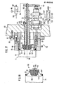
- FIG. 21 shows an immersion station 153 which immerses the bottom-side hull fold 43 essentially simultaneously with a first immersion device 154 and the hull fold 107 on the cover side with a second immersion device 155.
- the same parts as in FIGS. 11, 17 and -19 are provided with the same reference numbers in FIG. 21.
- the function of the immersion station 153 also corresponds to that in the immersion stations 11 and 115.
Landscapes
- Engineering & Computer Science (AREA)
- Mechanical Engineering (AREA)
- Chemical & Material Sciences (AREA)
- Dispersion Chemistry (AREA)
- Closing Of Containers (AREA)
Applications Claiming Priority (2)
| Application Number | Priority Date | Filing Date | Title |
|---|---|---|---|
| DE19843402197 DE3402197A1 (de) | 1984-01-24 | 1984-01-24 | Maschine und verfahren zur herstellung eines verpackungsbehaelters aus blech |
| DE3402197 | 1984-01-24 |
Publications (2)
| Publication Number | Publication Date |
|---|---|
| EP0149738A2 true EP0149738A2 (fr) | 1985-07-31 |
| EP0149738A3 EP0149738A3 (fr) | 1985-11-13 |
Family
ID=6225664
Family Applications (1)
| Application Number | Title | Priority Date | Filing Date |
|---|---|---|---|
| EP84113248A Withdrawn EP0149738A3 (fr) | 1984-01-24 | 1984-11-03 | Machine et procédé de fabrication d'un récipient d'emballage en tôle |
Country Status (3)
| Country | Link |
|---|---|
| EP (1) | EP0149738A3 (fr) |
| AU (1) | AU3624584A (fr) |
| DE (1) | DE3402197A1 (fr) |
Cited By (2)
| Publication number | Priority date | Publication date | Assignee | Title |
|---|---|---|---|---|
| WO1996014178A1 (fr) * | 1994-11-03 | 1996-05-17 | Carnaudmetalbox Plc | Appareil de soudage |
| CH706030A1 (de) * | 2012-01-18 | 2013-07-31 | Soudronic Ag | Verfahren und Vorrichtung zur Herstellung einer Dose mit einem Aufreissdeckel sowie Dose mit einem Aufreissdeckel. |
Family Cites Families (6)
| Publication number | Priority date | Publication date | Assignee | Title |
|---|---|---|---|---|
| US3246622A (en) * | 1963-03-11 | 1966-04-19 | Continental Can Co | Bottom seaming unit |
| DE1959758A1 (de) * | 1969-11-28 | 1971-06-03 | Std Services Ltd | Verfahren zum Herstellen von Druckgefaessen und Druckgefaess selbst |
| US3760751A (en) * | 1971-10-29 | 1973-09-25 | Pittsburh Aluminum | Container body and a method of forming the same |
| US3771345A (en) * | 1972-06-08 | 1973-11-13 | Standun | End forming station for metallic can body formers and the like |
| CH559128A5 (fr) * | 1972-12-04 | 1975-02-28 | Alusuisse | |
| US4030432A (en) * | 1975-01-24 | 1977-06-21 | Gulf & Western Manufacturing Company (Hastings) | Can trimming apparatus |
-
1984
- 1984-01-24 DE DE19843402197 patent/DE3402197A1/de not_active Withdrawn
- 1984-11-03 EP EP84113248A patent/EP0149738A3/fr not_active Withdrawn
- 1984-12-04 AU AU36245/84A patent/AU3624584A/en not_active Abandoned
Cited By (6)
| Publication number | Priority date | Publication date | Assignee | Title |
|---|---|---|---|---|
| WO1996014178A1 (fr) * | 1994-11-03 | 1996-05-17 | Carnaudmetalbox Plc | Appareil de soudage |
| WO1996014179A1 (fr) * | 1994-11-03 | 1996-05-17 | Carnaudmetalbox Plc | Appareil de soudage |
| AU693942B2 (en) * | 1994-11-03 | 1998-07-09 | Carnaudmetalbox Plc | Seaming apparatus |
| CH706030A1 (de) * | 2012-01-18 | 2013-07-31 | Soudronic Ag | Verfahren und Vorrichtung zur Herstellung einer Dose mit einem Aufreissdeckel sowie Dose mit einem Aufreissdeckel. |
| CN104125867A (zh) * | 2012-01-18 | 2014-10-29 | 苏德罗尼克股份公司 | 用于制造具有撕开盖的罐的方法和装置以及具有撕开盖的罐 |
| CN104125867B (zh) * | 2012-01-18 | 2016-09-07 | 苏德罗尼克股份公司 | 用于制造具有撕开盖的罐的方法和装置以及具有撕开盖的罐 |
Also Published As
| Publication number | Publication date |
|---|---|
| AU3624584A (en) | 1985-08-01 |
| DE3402197A1 (de) | 1985-08-01 |
| EP0149738A3 (fr) | 1985-11-13 |
Similar Documents
| Publication | Publication Date | Title |
|---|---|---|
| DE2353209C2 (de) | Verfahren zum Herstellen eines einstückigen, einendig offenen Behälters aus Metall, insbesondere Metalldose | |
| DE69506127T2 (de) | Falzvorrichtung | |
| DE3844117C2 (fr) | ||
| DE60201504T2 (de) | Verfahren und vorrichtung zum einhalsen der öffnung eines behälters | |
| EP0022211A1 (fr) | Procédé et appareil pour l'emboutissage d'un récipient à paroi mince à partir d'un flan | |
| DE2712604A1 (de) | Mehrfachziehwerkzeug | |
| DE69201360T2 (de) | Verfahren zum Formen der Öffnung eines Dosenrumpfes. | |
| DE2407986A1 (de) | Verfahren und einrichtung zum formen von metallbehaeltern | |
| DE69129309T2 (de) | Verpackung | |
| DE2419854C3 (de) | Verfahren und Drückmaschine zum Herstellen einer mehrrilligen Keilriemenscheibe aus Blech | |
| DE1291469C2 (de) | Verfahren und Vorrichtung zum Herstellen eines duennwandigen, oben offenen Behaelters aus einer Folie aus thermoplastischem Kunststoff | |
| DE2942124C3 (de) | Maschine zum Aufbringen einer Versiegelungshülse von flacher Gestalt auf einen Behälter | |
| WO2007051848A9 (fr) | Mandrin de serrage pour une impression numerique sur des corps de boites | |
| DE68903101T2 (de) | Herstellung von dosenkoerpern. | |
| DE2510543B2 (de) | Vorrichtung zum gleichzeitigen Aushalsen und Bördeln von Metalldosen | |
| DE2234162A1 (de) | Verfahren und vorrichtung zum herstellen eines pneumatischen luftreifens | |
| DE102016204209B4 (de) | Einsetzvorrichtung und Verfahren zum Einsetzen eines Rondenrings in einen Außenring einer Ronde | |
| DE3120887C2 (de) | Gesamtverbundwerkzeug zum Betrieb in einer Kurbeltrieb-Presse | |
| DE68927402T2 (de) | Stanz- und Nibbel-Maschine mit automatischer Werkzeugschnellwechselvorrichtung | |
| DE19517671C2 (de) | Vorrichtung für die Bildung eines geneckten und gebördelten Abschnitts an einem zylindrischen Hohlkörper | |
| DE69300891T2 (de) | Hochleistungs-Bördelmaschine zum Verschliessen von Konservendosen. | |
| WO2015010678A1 (fr) | Procédé et dispositif permettant de transférer un ensemble de segments de piston | |
| EP0149738A2 (fr) | Machine et procédé de fabrication d'un récipient d'emballage en tôle | |
| DE3853689T2 (de) | Verfahren und Vorrichtung zum Formen einer Filmkassette. | |
| DE2257210A1 (de) | Verfahren und vorrichtung zur herstellung eines metallenen dosenkoerpers |
Legal Events
| Date | Code | Title | Description |
|---|---|---|---|
| PUAI | Public reference made under article 153(3) epc to a published international application that has entered the european phase |
Free format text: ORIGINAL CODE: 0009012 |
|
| AK | Designated contracting states |
Designated state(s): AT BE CH DE FR GB IT LI LU NL SE |
|
| PUAL | Search report despatched |
Free format text: ORIGINAL CODE: 0009013 |
|
| AK | Designated contracting states |
Designated state(s): AT BE CH DE FR GB IT LI LU NL SE |
|
| STAA | Information on the status of an ep patent application or granted ep patent |
Free format text: STATUS: THE APPLICATION IS DEEMED TO BE WITHDRAWN |
|
| 18D | Application deemed to be withdrawn |
Effective date: 19860715 |
|
| RIN1 | Information on inventor provided before grant (corrected) |
Inventor name: SIEFERT, FRIEDRICH |