EP0149878A1 - Kettengliedvorrichtung für die Streckung von Folienmaterial und Streckapparat mit einer derartigen Kettengliedvorrichtung - Google Patents
Kettengliedvorrichtung für die Streckung von Folienmaterial und Streckapparat mit einer derartigen Kettengliedvorrichtung Download PDFInfo
- Publication number
- EP0149878A1 EP0149878A1 EP19840300405 EP84300405A EP0149878A1 EP 0149878 A1 EP0149878 A1 EP 0149878A1 EP 19840300405 EP19840300405 EP 19840300405 EP 84300405 A EP84300405 A EP 84300405A EP 0149878 A1 EP0149878 A1 EP 0149878A1
- Authority
- EP
- European Patent Office
- Prior art keywords
- link
- junction
- guide
- short
- member unit
- Prior art date
- Legal status (The legal status is an assumption and is not a legal conclusion. Google has not performed a legal analysis and makes no representation as to the accuracy of the status listed.)
- Granted
Links
- 239000000463 material Substances 0.000 title claims abstract description 77
- 230000003247 decreasing effect Effects 0.000 claims description 38
- 230000015572 biosynthetic process Effects 0.000 claims description 3
- 230000009467 reduction Effects 0.000 abstract description 9
- 230000007246 mechanism Effects 0.000 description 7
- 230000008859 change Effects 0.000 description 6
- 238000010438 heat treatment Methods 0.000 description 6
- 230000007423 decrease Effects 0.000 description 5
- 230000009471 action Effects 0.000 description 3
- 238000004519 manufacturing process Methods 0.000 description 3
- 238000002844 melting Methods 0.000 description 3
- 238000000034 method Methods 0.000 description 3
- 238000005299 abrasion Methods 0.000 description 2
- 230000001133 acceleration Effects 0.000 description 2
- 230000008901 benefit Effects 0.000 description 2
- 230000000694 effects Effects 0.000 description 2
- 239000000314 lubricant Substances 0.000 description 2
- 238000012423 maintenance Methods 0.000 description 2
- 229920003002 synthetic resin Polymers 0.000 description 2
- 239000000057 synthetic resin Substances 0.000 description 2
- XEEYBQQBJWHFJM-UHFFFAOYSA-N Iron Chemical compound [Fe] XEEYBQQBJWHFJM-UHFFFAOYSA-N 0.000 description 1
- 230000033228 biological regulation Effects 0.000 description 1
- 239000011248 coating agent Substances 0.000 description 1
- 238000000576 coating method Methods 0.000 description 1
- 239000002131 composite material Substances 0.000 description 1
- 238000010276 construction Methods 0.000 description 1
- 238000001816 cooling Methods 0.000 description 1
- 230000006866 deterioration Effects 0.000 description 1
- 238000010030 laminating Methods 0.000 description 1
- 230000002093 peripheral effect Effects 0.000 description 1
- 230000001105 regulatory effect Effects 0.000 description 1
- 238000004904 shortening Methods 0.000 description 1
- 229920001169 thermoplastic Polymers 0.000 description 1
- 229920001187 thermosetting polymer Polymers 0.000 description 1
- 239000004416 thermosoftening plastic Substances 0.000 description 1
Images






Classifications
-
- B—PERFORMING OPERATIONS; TRANSPORTING
- B29—WORKING OF PLASTICS; WORKING OF SUBSTANCES IN A PLASTIC STATE IN GENERAL
- B29C—SHAPING OR JOINING OF PLASTICS; SHAPING OF MATERIAL IN A PLASTIC STATE, NOT OTHERWISE PROVIDED FOR; AFTER-TREATMENT OF THE SHAPED PRODUCTS, e.g. REPAIRING
- B29C55/00—Shaping by stretching, e.g. drawing through a die; Apparatus therefor
- B29C55/02—Shaping by stretching, e.g. drawing through a die; Apparatus therefor of plates or sheets
- B29C55/20—Edge clamps
Definitions
- the present invention relates to a link device or a linkage for stretching a sheet material, for instance a thermo-plastic synthetic resin film, in the longitudinal, transverse or biaxial direction and to a stretching apparatus using said link device.
- the stretching apparatus disclosed in Japanese .. Patent; Publication No. SHO 43-5560 has a pair of stretching devices provided at opposite sides along the longitudinal direction of the stretching apparatus.
- Each of the stretching devices comprises an endless link device comprising a plurality of link members arranged to form a pantograph structure, a plurality of sliding shoes provided at the bottom side of the endless link device, means for circulating the endless link device and a rail unit to guide slidably the sliding shoes.
- the means for circulating the endless link device comprises a first sprocket provided at the entrance of the stretching apparatus and a second sprocket provided at the exit of the stretching apparatus.
- the endless link device is meshed with the sprockets.
- the rail unit is provided between a position where the endless link device leaves from the first sprocket and a position where the endless link device connects with the second sprocket.
- the rail unit has an outside rail, a central rail and an inside rail.
- a first gauge between the outside and inside rails becomes narrow in the direction from the first sprocket to the second sprocket to reduce the height of and to expand the length of the pantograph structure for imparting a longitudinal stretching to the film.
- the sliding shoes comprise a series of outside shoes being slidably in contact with the outside rail, a series of central shoes being slidably in contact with the central rail ahd a series of inside shoes being slidably in contact with the inside rail.
- Each of the shoes is in contact with each of the rails at the bottom and side surfaces thereof.
- the gauge between the rail units provided at both sides along the stretching apparatus becomes wide in the direction from the first sprocket to the second sprocket to impart a transverse stretching to the film.
- the stretching apparatus further, it is not possible to provide the rail unit around the sprockets because if the rail unit is provided around the sprockets, there occurs an interference between the force acting on each of the sprockets and the force acting; on each of the shoes through the endless link device meshing with each of the sprockets.
- the rail unit is provided only between both of :the sprockets.
- Such an arrangement of rail unit is not suitable for high speed operation of the stretching apparatus, because the shoes have to engage on and have to disengage.-from the rail at the entrance of the sprocket and at the exit of the sprocket respectively.
- the stretching apparatus furthermore, since a very large force acts on the rails as mentioned above, it is necessary to use rigidly built rails .
- a stretching ratio in the longitudinal direction it is necessary to change the gauge between the outside rail and the inside rail.
- Changing the gauge between the rigidly built rails on the rail unit cannot be accomplished with a simple mechanism for varying and adjusting the gauge.
- a rail unit is changed with another one having a different gauge between the outside rail and the inside rail for varying the stretching ratio.
- This changing work costs workers in a factory immense trouble. Actually, therefore, the factory has to prepare several stretching apparatuses having different gauges to produce stretched films having different streching ratios if the factory wants to do so.
- Japanese Patent Publication No. SHO 44-71.55 teacher a stretching apparatus similar to the stretching apparatus shown in Japanese Patent Publication No. SHO 43-5560 mentioned above except for rotatable rollers provided to support the endless link device on the rail unit instead of the sliding shoes.
- Each of the rotatable rollers for supporting the weight of the endless link device is constructed by a caster roller which is swingable in a horizontal plane.
- the stability of circulation of the endless link device at high speed can not be accomplished, because the caster rollers receive centrifugal force during travel of the endless link device around the sprockets and the directions of the caster rollers become unstable at that time. This phenomenon was clearly observed on the practical operation of the stretching apparatus having the same construction disclosed in Japanese Patent Publication No. SHO 44-7155 at a speed of about 200 m/min. or more.
- An object of the present invention is to realize high-speed running of a special link in order to eliminate the above-mentioned drawbacks.
- Another object of the present invention is to make it possible to drive the link device and stretch the sheet material with stability even at a high speed.
- Still another object of the present invention is to provide a link device which can easily change the stretching ratio of the sheet material and a stretching apparatus using said link device.
- a pantograph-like link member unit consists of two kinds of link members, i.e., long and short ones, and the links of the same length in the link member unit are adjacently arranged in the running direction of the link member unit.
- a sub-link which maintains a position normal to the running direction of the link member unit.
- a roller is fitted to the sub-link. Moreover to said link member unit is attached a guide-roller to regulate the degree of folding of said link member unit. A gripper to grip the side edge of the sheet material is fitted to the sub-link or to the link member unit.
- each of the rail units consists of a pair of guide-rails and the gauge of the guide-rails is set so as to change the longitudinal stretching ratio of the sheet material.
- the pantograph-like link member unit is not supported on sliders but supported on rollers.
- the roller being attached to the sub-link which is attached substantially at a right angle to the running direction of the link member unit such that said roller can move in the running direction of the link member unit, can rotate smoothly.
- the total running resistance of the endless chain is extremely reduced as compared with the conventional one. Accordingly the endless chain can be driven with a small force and in the section where the link member units mesh with the sprocket, the force can be reduced which is caused by the interference between the sprocket and the rail through the link member units.
- the link member unit consists of long and short link members, it is possible to mesh the link member unit with the drive sprocket in the state where the short link is stretched to the limit or nearly to the limit, thereby avoiding any extremely large force caused by the interference between the drive sprocket and the rail through the link member units.
- the link member unit since the link member unit consists of long and short link members, it is possible to mesh the link member unit with the drive sprocket in the state where the short link is stretched to the limit or nearly to the limit, thereby avoiding any extremely large force caused by the interference between the drive sprocket and the rail through the link member units.
- the link member unit can run at a high speed with stability.
- stretching of the sheet material can be accomplished at high speed and with stability.
- the gauge of the guide-rails which regulate the degree of folding of the link member unit through regulation of the relative positions of the rollers, can be easily changed by a small force. Therefore, an adjuster for adjusting the gauge between the guide-rails can be installed and the degree of folding of the link member unit can be easily changed meeting the necessary production requirements.
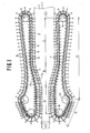
- a film 1-1 as a sheet material 1 to be stretched is transported in the direction of the arrow.
- the film 1-1 is clipped by the grippers 2, stretched biaxially in the longitudinal and transverse directions while being transported in the direction of the arrow.
- Each, gripper 2 is attached to the sub-link 4 fitted on the pantograph-like link member unit 3.
- the sub-link 4 is held substantially at a right angle to the running direction of the link member unit 3.
- a plurality of such link member units 3 are connected together, forming an endless chain 5 in a loop form.
- a roller 6 is attached to the link member unit 3.
- the roller 6 engages a guide-rail 7.
- One rail unit is provided for each endless chain 5.
- Each rail unit is composed of a pair of guide-rails 7.
- the guide-rail 7 is endless and the travel path of the link member unit 3 is regulated by the guide-rail 7.
- the endless chain 5 is driven by sprockets.
- three sprockets 8, 9, 10 are provided for each endless chain 5.
- sprocket 9, or 10 is preferable.
- the link member unit 3 is foldable, that is, can be shortened or lengthened through the movement of a plurality of link members which constitute said unit 3.
- the angle of folding of the link member unit 3 depends on the relative positions of the rollers 6 and said relative positions of the rollers 6 depend on the gauge of guide-rails 7.
- the angle of folding regulates the pitch of sub-links 4 and the pitch of grippers 2.
- the pitch of grippers 2 is set short on the pre-heating section A for the film 1-1.
- the pitch of grippers 2 is gradually widened and at the same time the running path of the gripper 2 is gradually spread toward the end of the stretching section B.
- the film 1-1 which is clipped on both side edges with the grippers 2 is stretched at the same time in the longitudinal direction and in the transverse direction in the stretching section B.
- the pitch of grippers 2 is set nearly constant. After the gripper 2 releases the film and then is turned at the sprocket 9, the pitch of grippers 2 is made the longest in a longest gripper pitch section D.
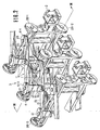
- pantograph-like link member unit 3 Next, referring to Figs. 2-5, a description of the pantograph-like link member unit 3 will be made.
- the link member unit 3 includes short and long link members 11 connected foldably like a pantograph.
- the pantograph arrangement is as follows. There are short links 12 and 13, and long links 14 and 15. As indicated in Fig. 3 this arrangement is symmetric with respect to the upper and lower side thereof, that is, the upper side of the pantograph is composed of short links 12-1 and 13-1 and long links 14-1 and 15-1, while the lower side of the pantograph is composed of short links 12-2 and 13-2, and long links 14-2 and 15-2.
- Short links 12 and 13 are connected together by means of a connecting pin 17 provided at the junction 16, and long links 14 and 15 are connected together by means of a connecting pin 19 provided at the junction 18.
- Short link 12 and long link 14 as well as short link 13 and long link 15 are connected together by a connecting pin 21 at the junction 20.
- adjacent link member units 3 are connected together by the connecting pin 21.
- Long link 15 has an extended portion 22 on the side of the connecting pin 19.
- the extended portion 22 is about as long as the distance between the connecting pin 21 and the connecting pin 19 for long link 15.
- the sub-link 4 is swingably connected with the extended portion 22 via the connecting pin 23.
- the connecting pin 23 constitutes the junction between the sub-link 4 and the extended portion 22.
- the sub-link 4 is swingably connected with the junction 20 by the connecting pin 21.
- the connecting pin 21 and the sub-link 4 are mutually slidable in a long slot 24 formed on the sub-link 4.
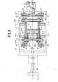
- the sub-link 4 is an element with a laterally extending U-shaped section in the vertical direction.
- the upward extending portion 25 and the downward extending portion 26 each has a support 27 fixed thereto.
- Each support 27 has a roller 28 which supports the link member unit 3 and carries the sub-link 4 in the running direction of the link member unit.
- the roller 28 is rotatably held on the support 27.
- a gripper 2 for clipping on the side edge of the sheet material is protruded from the midway portion of the vertically extending portion of the sub-link 4.
- guide-rolles 6 which are rotatable in the horizontal plane. It is preferred that guide-rollers are arranged vertically symmetric with respect to the plane F-F in which the sheet material is held by the gripper 2.
- the guide-roller 6 engages the guide-rail 7.
- the guide-rails 7-1 and 7-2 are attached to the rail 100.
- the guide-rails 7-3 and 7-4 are attached to the rail 101 which is slidably fitted to the rail 100.
- the roller 28 rolls on the rails 100 and 101.
- the rollers 28-1 and 28-2 move on the rail 100, while the rollers 28-3 and 28-4 move on the rail 101.
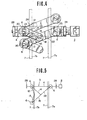
- a gauge adjuster 102 which slides and shifts the rail 101 against the rail 100. Therefore, if the guide-rails 7-1, 7-2 are called guide-rail 7a and the guide-rails 7-3, 7-4 are called guide-rail 7b, the gauge between the guide-rail 7a and the guide-rail 7b can be adjusted by the action of the gauge adjuster 102. As modeled in Fig. 5, the degree of folding of the link member unit and the pitch of grippers 2 can be determined by adjusting the gauge between the guide-rails 7a and 7b.
- guide-rails 7 are arranged according to the stretching ratio of the sheet material 1, and the gauge between the guide-rails 7a and 7b in a pair of guide-rails 7 is adjusted according to the stretching ratio of the sheet material 1 to be stretched.
- the gauge between the guide-rails 7a and 7b in a pair of guide-rails 7 is adjusted according to the stretching ratio of the sheet material 1 to be stretched.
- the stretching in the longitudinal direction and in the transverse direction takes place simultaneously in the stretching section B.
- the link member unit 3 runs supported on the rollers 28.
- the running resistance of the roller 28, which is free to roll, is remarkably lower than that of the conventional slider of the conventionel apparatus.
- the direction of its rotational movement invariably agrees with the running direction of the link member unit 3, resulting in a low stabilized running resistance.
- the guide-roller 6 is equally rotatable and accordingly the running resistance remains equally low between the guide-rollers 6-3, 6-4 and guide-rails 7-3, 7-4 to which is applied the stretching force of the sheet material 1.
- the total running resistance of the endless chain 5 is maintained low, and it is possible to drive the endless chain 5 with a small force.
- the link member unit 3 is composed of long and short link members, it is possible to make the link member unit 3 engage with the sprocket 10 in the state when the short links 12 and 13 are stretched nearly to the limit, and, as illustrated in Fig. 1, the sprocket 10 is taken as the drive sprocket.
- the endless chain 5 runs smoothly, facilitating high speed running.
- the roller 28 gives an effect of reducing the running resistance of the link member unit 3. Since the drive force to drive the endless chain 5 becomes small according to the decrease of the running resistance, the force of the guide roller 6 with which it grasps the guide rail 7 decreases, thereby decreasing the total running resistance of the endless chain. Moreover, as stated above, the roller 28 rolls always in the running direction of the link member unit and therefore the running resistance is maintained constant. Thus the link member unit 3 is driven smoothly and stably with a high speed, arid accordingly the stable stretching of the sheet material 1 is obtained.
- the gauge between the guide-rails 7-3, 7-4 and the guide-rails 7-1, 7-2 can be easily adjusted by the gauge adjuster 102.
- the longitudinal stretching ratio of the sheet material 1 can be set or changed easily and continuously.
- the roller 28 yields the following benefits.
- the consumption of the lubricant to be supplied between the rail and the roller 28 can be drastically decreased as compared with the use of the slider, resulting in a remarkable : reduction of lubricant splashing on the film.
- the quality of a film is improved drastically.
- a decrease of abrasion compared with the slider will prolong the life of the apparatus and cut back the expense for maintenance.
- the link members 11 and the guide-rollers 6 are arranged symmetrically with respect to the plane in which the sheet material 1 is held. And as a consequence the loads generating in any member of link member units 3 are well balanced. Accordingly there is no generation of a moment and twisting force making the running unstable and an excellent characteristic for high-speed running can be guaranteed.
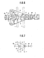
- the sub-link 4 lies over the junction 18 of long links 14 and 15 and the junction 16 of short links 12 and 13 in said link member unit 3.
- the guide-roller 6 is provided at the junction 18 of long links 14 and 15, at the junction 20 of long link 14 and short link 12 and at the junction 20 of long link 15 and short link 13.
- Such an arrangement of the guide-rollers 6, unlike the arrangement in Fig. 6, is triangular and therefore the engagement of the guide-roller 6 with the guide-rail 7 becomes more stable and as a consequence the folding movement of the link member unit 3 becomes more stable.
- the sub-link 4 lies over the junction 18 of long links 14 and 15 and the junction 16 of short links 12 and 13.
- the guide-roller 6 is provided each at the junction 16, at the junction 20 of long link 14 and short link 12 and at the junction 20 of long link 15 and short link 13.
- the guide-roller 6a at the junction 16 and the guide-roller 6b at the junction 20 are vertically staggered in position.
- the guide-roller 6a is disposed below the link member unit 3, while the guide-roller 6b is disposed above said unit 3.
- the guide-rail 7a engages with the guide-roller 6a below the unit 3, while the guideS rail 7b engages with the guide-roller 6b above unit 3.
- the long links 14, 15 and the short links 12, 13 are not arranged with the vertically symmetric formation illustrated in Fig. 3.
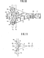
- an intermediate link unit is added, and a pair of intermediate links 40-1, 40-2 which are rotatably connected to each other are connected to the adjacent long links 14 and 15 of two adjacent link member units 3.
- a pair of intermediate links 40-1, 40-2 which are rotatably connected to each other are connected to the adjacent long links 14 and 15 of two adjacent link member units 3.
- an intermediate sub-link 42 lying over the junction 20 of the long link and short link and over the junction 41 of the link members 40-1 and 40-2 of the intermediate links 40.
- the guide-rollers 6 are provided at the junction 18 of long links 14 and 15 and at the junction 20 of long links 14, 15 and short links 12, 13.
- the pitch between the grippers 2 is shorter by introducing the intermediate sub-links 42.
- a transverse necking is liable to occur in non-gripped edges of both sides of the film between grippers which often causes a problem in production and a deterioration in the quality of the product.
- the pitch of the grippers 2 be made shorter and in this example just this effect can be obtained.
- the number of guide-rollers 6 can be substantially decreased as compared with the numbers of sub-links 4, 42 and grippers 2. As a result, the running resistance of the guide-roller against the guide-rail 7 can be decreased and then the force required for driving the endless chain 5 can be decreased.
- the guide-rail 7 has to be made thicker for increasing rigidity and as a consequence an increase in the length of the link member is inevitable.
- the addition of the intermediate link 40 will guarantee the rigidity of the link member unit 3, while the presence of the intermediate sub-link 42 will keep the pitch between grippers 2 short.
- a high speed running can be realized with the rigidity of every part secured.
- Figures 14 and 15 illustrate another example of adding a intermediate link.
- the intermediate links 40 are added to the arrangement of Figs. 10 and 11. tamely, there are provided the intermediate link 40 and the intermediate sub-link 42, while the guide-rollers 6a and 6b are vertically staggered in position.
- the intermediate link 40 serves to guarantee the rigidity of the link member unit 3, while the intermediate sub-link 42 keeps the pitch between grippers 2 short.
- the numbers of guide-rollers 6, guide-rails 7 and link members can be reduced as compared with their numbers in the example of Figs. 12 and 13.
- the gripper 2 is attached to the sub-link 4 or the intermediate sub-link 42. As illustrated in Fig. 16, however, the gripper 2 may be fitted to the link member unit 3. In the example of Fig. 16, the gripper 2 is fitted to the end of the extended portion 15a of one long link 15. The direction of the gripper 2 fitted to the long link 15 will change depending on the folding movement of the link member unit 3. For a sheet material whose stretching is virtually unaffected by change of the direction of the gripper 2, application of such an arrangement will be allowed. In the present example, if the sub-link 4 is a laterally extending U-shaped member, an interference will occur-between the extended portion 15a and the sub-link 4 and to prevent the interference the affected part of the sub-link 4 is split into upper and lower members.
- connection of the sub-link 4 on the side of long links 14, 15 is constructed such that only rotational movement is allowed, while the connection on the opposite side is made slidable in a long slot 24.
- the connection system is not limited to this embodiment, namely it is possible to make the connection on the side of long links 14, 15 slidable and to make the connection on the opposite side rotatable.
- the stretch tension transmitted from the gripper 2 will be given to the link member unit 3 via the rotatable connection on the opposite side to the gripper 2.
- the stretch tension will be more likely to be borne by the, guide-roller 6 and the guide-rail 7 on the opposite side to the gripper 2, and this will bring about the advantage of realizing stable stretching.
- the rollers 28 may be arranged at an interval of every other sub-link 4 or at a longer interval.
- Figure 3 is an example of rollers 28 being arranged in vertical symmetry. As shown in Fig. 17, however, the rollers 28 may be provided only below the sub-link 4. In that case it would be desirable to provide the roller stoppers 103, 104 extending over the roller Then the vertical movement of the rollers 28 would be constrained and a dancing of the link member unit 3 in running as well as its rotational movement under action of a moment would be prevented. Thus even if the roller 28 exists only below the sub-link 4, a smooth running with a low resistance will be guaranteed.
- Figure 1 shows an example in the case where the sheet material 1 is biaxially stretched at the same time.
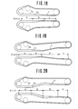
- Figures 18, 19 and 20 show examples of a guide-rail arrangement for other typical patterns of stretching.
- Figure 18 is a case of the sheet material being stretched only in the longitudinal direction.
- a pair of guide-rails 7 provided on both transverse sides of the sheet material are arranged parallel to the running direction X of the sheet material.
- the gauge between the guide-rails 7a and 7b in the pair of guide-rails 7 is adjusted to be parallel in section a, is gradually made narrower in section b and is again parallel in section c. Therefore, in section b the angle of folding of the link member unit 3 gradually changes, the pitch of grippers 2 gradually increases and thus the sheet material is stretched in the longitudinal direction.
- the section a is a pre-heating zone and the section c is a heatset zone or a cooling zone.
- the stretching apparatus is available as a longitudinal stretching machine for stretching the sheet material in the longitudinal direction alone.
- the surface of material is subjected to coating or laminating with another film.
- a typical system for longitudinal stretching is a multi-roll system utilizing the peripheral speed difference between rolls.
- the coat or the composite layer is composed of a low-melting point material
- the low-melting point material in contact with the surface of the rolls which can also pre-heat the sheet material becomes melted and sticks to the rolls, thereby resulting in failing to be stretched.
- the system illustrated in Fig. 18 which can perform non-contact heating of the material, there is no sticking problem as exists in the roll system and accordingly it is possible to make a longitudinal stretching of the sheet material coated with a low-melting point material, unlike in the roll system.
- Figure 19 is an example of stretching a sheet material in the longitudinal direction and then in the transverse direction.
- a pair of guide-rails 7 disposed on both sides of the sheet material in the transverse direction are arranged parallel to the running direction X of said material in sections a and b, but in section d these rails are gradually spread out, and again in section c they become parallel.
- the gauge between the guide-rails 7a and 7b is adjusted to be gradually narrower in section b and to be parallel in sections a, d and c.
- the sheet material is preheated in section a, stretched in the longitudinal direction in section b, stretched in the transverse direction in section d and heat-set or cooled in sectioh c.
- separate stretching machines units are usually arranged in series. According to the present invention, as seen in Fig, 19, biaxial successive stretching can be performed easily within a single device.
- Figure 20 is an example of stretching the sheet material in the transverse direction and then in the longitudinal direction.
- a pair of guide-rails 7 are, in section a, arranged parallel to the running direction X of the sheet material, spread out in section d, and parallel again in sections b and c.
- the gauge between the guide-rails 7a and 7b is adjusted to be gradually narrower in section b and parallel in the other sections a, d and c.
- the sheet material is preheated in section a, stretched in the transverse direction in section d, stretched in the longitudinal direction in section b and thermoset or cooled in section c.
- the procedure for stretching in the longitudinal and transverse directions can be reversed.
- Figures 1, 18, 19 and 20 illustrate typical stretching patterns, but the present invention is not limited to these patterns.
- the demand can be easily satisfied by adjusting the gauge between the guide-rails 7a and 7b gradually narrow in section c in Figs. 19 and 20.
- the present invention can also satisfy the demand, when transverse stretching after biaxial stretching is demanded.
- the present invention could realize a two-step stretching such as additional longitudinal stretching after longitudinal stretching or additional transverse stretching after transverse stretching.
- the present invention can be adapted to whatever stretching sequence required from production needs.
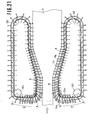
- Figure 21 illustrates a different embodiment of the drive mechanism for the endless chain link 5 from that given in Fig. 1.
- This embodiment there is one drive sprocket 50 for engaging each endless chain 5.
- the drive sprocket 50 is located at the position where the decreasing pitch section E begins.
- the gauge between the guide-rails 7a and 7b is gradually increased, while the pitch of grippers 2 is gradually decreased.
- the guide-rails 51a, 51b to guide the guide-roller 6 are provided as well as the guide-rails 7a and 7b.
- each endless chain 5 can be easily driven by only one drive sprocket 50.
- the drive sprocket 50 may be located at the exit 52. In that case, the link member unit 3 will be pulled in the running direction on the decreasing pitch section E and therefore the guide-rails 51a, 51b can be removed.
- an auxiliary sprocket may be provided at each turning point of the endless chain 5.
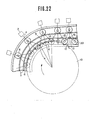
- a sprocket 10 is provided at the position where the decreasing pitch section E begins, and, after the intersecting angle between the short links 12, 13 is made less than 180° by engaging with said sprocket 10, the pitch of grippers is decreased.
- the intersecting angle K between the short links 12 and 13 can be obtained by making the link member junctions 16, 20 engage the sprocket 10.
- R is the radius of pitch circle of the sprocket 10
- 1 is the length of short links 12, 13.
- decreasing the radius of the sprocket 10 will mean increasing unsteadiness of acceleration due to the rotational radius of the link device about the center of the sprocket being small and thereby a smooth running at high speed can not be expected.
- the heavy abrasion of the roller 28 caused by the unsteadiness of the acceleration of the roller 28 which supports the link device makes the maintenance troublesome and the high speed running very difficult.
- the short link 12 and the short link 13 of the adjacent link member units 3 are forcibly positioned in a straight row while the sprocket 10 meshes with the link member unit.
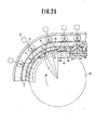
- sprocket 10-1 with the radius two times the radius of the sprocket in the case of Fig..22 can be employed to get the same value of K as obtained in the case of Fig 22. Since the value of K can be made small with the radius of sprocket kept larger than necessary value, the reduction of the pitch of grippers can be easily accomplished at the same time with attainment of high-speed performance.
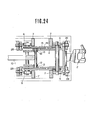
- the short link has a prominent portion 60 protruding in the opposite direction to the side of long links 14, 15, and at the position where the decreasing pitch section E begins, a guide plate 61 is provided.
- the guide plate 61 engages with the prominent portion 60 and moves the junction 16 of short links 12 and 13 to the side of long links 14, 15.
- the engaging face 62 of the guide plate 61 is linearly inclined as shown in Fig. 25, the prominent portion 60 can smoothly slide on the face 62. And at the end of the face 62, the angle K between short links 12, 13 is forcibly reduced to a desired value and thus the subsequent reduction of the pitch of grippers 2 is facilitated.
- the face 62 may be non-linear, or smoothly curvilinear.
- the guide plate 61 in Fig. 25 is a rotatable disk 61-1 in Fig. 26, the relative slipping between the rotatable disk 61-1 and the prominent portion 60 will become very small, assuring a smoother engagement.
- the engaging piece 61 or the rotatable disk 61-1 may be located at any position in the decreasing pitch section E.
- the guide plate 61 or the rotatable disk 61-1 is desired to be designed so that the angle K becomes less than 170° to facilitate the subsequent reduction of pitch of grippers 2.
- an engaging piece 71 which engages with the sprocket 10-2 and has a larger radius than that of the engaging piece 70 provided at the junction which connects the adjacent link member units 3.
- the distance between the center of sprocket and the junction 16 becomes Ro + r, where Ro is the root circle radius on the tooth surface of the sprocket 10-2 which engages with the engaging piece 71 and r is the radius of the engaging piece 71.
- the distance between the center of the sprocket and the junction 20 is equal to R, i.e. the pitch circle radius of the sprocket 10-2. Accordingly the angle K becomes small according to the amount of Ro + r - R which represents the distance between the junction 16 and junction 20 in the radial direction. As a consequence even after the sprocket 10-2 releases the link members unit 3, the pitch of grippers 2 is easily decreased, and high-speed running can be obtained by making the radius of the sprocket large.
- the pitch circle radius on the tooth surface of the sprocket 10-3 is made alternately large and small.
- the pitch circle diameter R 2 on the tooth surface 80 which engages with the junction 16 to connect short link 12 and short link 13 is made larger than the pitch circle radius R 1 on the tooth surface 81 which engages with the junction 20 connecting the adjacent link member units 3.
- R 1 R 2
- the state of Fig. 22 is generated.
- a ring 90 is provided at the junction 16 of short link 12 and short link 13, while at the position where the decreasing pitch section E begins a guide-plate 61 which engages with said ring 90 and shifts the junction 16 to the side of long links 14, 15 is provided.
- the ring 90 moves along the guide surface 62 of the guide-plate 61 and at the end of the guide surface 62 the angle K between short link 12 and short link 13 is forcibly reduced to a required value.
- a smoother reduction of the angle K will be possible.
- the guide surface 62 is curvilinear, a smoother engagement will be possible.
- a rotatable disk may be employed as the guide-plate 61.
Landscapes
- Engineering & Computer Science (AREA)
- Mechanical Engineering (AREA)
- Shaping By String And By Release Of Stress In Plastics And The Like (AREA)
Priority Applications (3)
| Application Number | Priority Date | Filing Date | Title |
|---|---|---|---|
| DE8484300405T DE3465926D1 (en) | 1984-01-24 | 1984-01-24 | Link device for stretching sheet material and stretching apparatus using said link device |
| EP19840300405 EP0149878B1 (de) | 1984-01-24 | 1984-01-24 | Kettengliedvorrichtung für die Streckung von Folienmaterial und Streckapparat mit einer derartigen Kettengliedvorrichtung |
| US06/910,360 US4807336A (en) | 1984-01-24 | 1986-09-22 | Link device for stretching sheet material and stretching apparatus using said link device |
Applications Claiming Priority (1)
| Application Number | Priority Date | Filing Date | Title |
|---|---|---|---|
| EP19840300405 EP0149878B1 (de) | 1984-01-24 | 1984-01-24 | Kettengliedvorrichtung für die Streckung von Folienmaterial und Streckapparat mit einer derartigen Kettengliedvorrichtung |
Publications (2)
| Publication Number | Publication Date |
|---|---|
| EP0149878A1 true EP0149878A1 (de) | 1985-07-31 |
| EP0149878B1 EP0149878B1 (de) | 1987-09-09 |
Family
ID=8192541
Family Applications (1)
| Application Number | Title | Priority Date | Filing Date |
|---|---|---|---|
| EP19840300405 Expired EP0149878B1 (de) | 1984-01-24 | 1984-01-24 | Kettengliedvorrichtung für die Streckung von Folienmaterial und Streckapparat mit einer derartigen Kettengliedvorrichtung |
Country Status (2)
| Country | Link |
|---|---|
| EP (1) | EP0149878B1 (de) |
| DE (1) | DE3465926D1 (de) |
Cited By (13)
| Publication number | Priority date | Publication date | Assignee | Title |
|---|---|---|---|---|
| DE3741572A1 (de) * | 1987-12-08 | 1989-06-22 | Brueckner Maschbau | Vorrichtung zum strecken einer bewegten materialbahn |
| FR2654383A1 (fr) * | 1989-11-14 | 1991-05-17 | Dornier Gmbh Lindauer | Chaine a pinces a pas progressivement variable pour traitement simultane de feuilles minces en bande dans les sens transersal et longitudinal. |
| EP0480253A3 (en) * | 1990-10-11 | 1993-05-05 | Fibronit S.R.L. | Device for transverse extension of retiform materials and in particular fibrillar polymeric film |
| US5287958A (en) * | 1990-03-01 | 1994-02-22 | Bruckner Maschinenbau Gernot Bruckner Gmbh & Co. Kg | Device for stretching and fixing sheet |
| WO2000029197A1 (en) * | 1998-11-13 | 2000-05-25 | Minnesota Mining And Manufacturing Company | Methods of stretching films and such films |
| US6303067B1 (en) | 1998-11-13 | 2001-10-16 | 3M Innovative Properties Company | Method of stretching films according to an overbias or overstretch stretch profile |
| US6965474B2 (en) | 2003-02-12 | 2005-11-15 | 3M Innovative Properties Company | Polymeric optical film |
| US7110072B2 (en) | 2003-02-12 | 2006-09-19 | 3M Innovative Properties Company | Compensators for liquid crystal displays |
| US7132065B2 (en) | 2003-02-12 | 2006-11-07 | 3M Innovative Properties Company | Process for manufacturing polymeric optical film |
| CN109269883A (zh) * | 2018-11-12 | 2019-01-25 | 凯尔测控试验系统(天津)有限公司 | 一种面内双轴拉伸用宽度自适应夹具 |
| CN113727826A (zh) * | 2019-04-18 | 2021-11-30 | 株式会社日本制钢所 | 拉伸装置及拉伸装置的部件更换方法 |
| CN115087536A (zh) * | 2020-04-22 | 2022-09-20 | 芝浦机械株式会社 | 拉伸装置以及夹具个数调节方法 |
| CN118219543A (zh) * | 2024-04-17 | 2024-06-21 | 扬州博恒新能源材料科技有限公司 | 一种用于薄膜的双向拉伸设备 |
Families Citing this family (1)
| Publication number | Priority date | Publication date | Assignee | Title |
|---|---|---|---|---|
| JP4845619B2 (ja) | 2006-07-19 | 2011-12-28 | 東芝機械株式会社 | シート・フィルムの斜め延伸方法およびクリップ式シート・フィルム延伸装置 |
Citations (4)
| Publication number | Priority date | Publication date | Assignee | Title |
|---|---|---|---|---|
| US3195177A (en) * | 1961-08-06 | 1965-07-20 | Shin Mitsubishi Jukogyo Kk | Apparatus for stretching thermoplastic film |
| US3276071A (en) * | 1963-12-02 | 1966-10-04 | Hitachi Ltd | Apparatus for stretching the film in two axial directions simultaneously by using link mechanism |
| DE1234374B (de) * | 1961-03-21 | 1967-02-16 | Brueckner Trocknerbau Inh Gern | Vorrichtung zum biaxialen Recken einer Materialbahn in Laengs- und Querrichtung |
| US3491402A (en) * | 1967-05-25 | 1970-01-27 | Hitachi Ltd | Apparatus for biaxially stretching a film material |
-
1984
- 1984-01-24 EP EP19840300405 patent/EP0149878B1/de not_active Expired
- 1984-01-24 DE DE8484300405T patent/DE3465926D1/de not_active Expired
Patent Citations (5)
| Publication number | Priority date | Publication date | Assignee | Title |
|---|---|---|---|---|
| DE1234374B (de) * | 1961-03-21 | 1967-02-16 | Brueckner Trocknerbau Inh Gern | Vorrichtung zum biaxialen Recken einer Materialbahn in Laengs- und Querrichtung |
| DE1274337B (de) * | 1961-03-21 | 1968-08-01 | Brueckner Trocknerbau Inh Gern | Vorrichtung zum biaxialen Recken einer Materialbahn in Laengs- und Querrichtung |
| US3195177A (en) * | 1961-08-06 | 1965-07-20 | Shin Mitsubishi Jukogyo Kk | Apparatus for stretching thermoplastic film |
| US3276071A (en) * | 1963-12-02 | 1966-10-04 | Hitachi Ltd | Apparatus for stretching the film in two axial directions simultaneously by using link mechanism |
| US3491402A (en) * | 1967-05-25 | 1970-01-27 | Hitachi Ltd | Apparatus for biaxially stretching a film material |
Cited By (18)
| Publication number | Priority date | Publication date | Assignee | Title |
|---|---|---|---|---|
| DE3741572A1 (de) * | 1987-12-08 | 1989-06-22 | Brueckner Maschbau | Vorrichtung zum strecken einer bewegten materialbahn |
| FR2654383A1 (fr) * | 1989-11-14 | 1991-05-17 | Dornier Gmbh Lindauer | Chaine a pinces a pas progressivement variable pour traitement simultane de feuilles minces en bande dans les sens transersal et longitudinal. |
| US5287958A (en) * | 1990-03-01 | 1994-02-22 | Bruckner Maschinenbau Gernot Bruckner Gmbh & Co. Kg | Device for stretching and fixing sheet |
| EP0480253A3 (en) * | 1990-10-11 | 1993-05-05 | Fibronit S.R.L. | Device for transverse extension of retiform materials and in particular fibrillar polymeric film |
| WO2000029197A1 (en) * | 1998-11-13 | 2000-05-25 | Minnesota Mining And Manufacturing Company | Methods of stretching films and such films |
| US6303067B1 (en) | 1998-11-13 | 2001-10-16 | 3M Innovative Properties Company | Method of stretching films according to an overbias or overstretch stretch profile |
| US6358457B1 (en) | 1998-11-13 | 2002-03-19 | 3M Innovative Properties Company | Method of stretching films according to an overbias or overstretch profile |
| US7099083B2 (en) | 2003-02-12 | 2006-08-29 | 3M Innovative Properties Company | Polymeric optical film |
| US6965474B2 (en) | 2003-02-12 | 2005-11-15 | 3M Innovative Properties Company | Polymeric optical film |
| US7110072B2 (en) | 2003-02-12 | 2006-09-19 | 3M Innovative Properties Company | Compensators for liquid crystal displays |
| US7132065B2 (en) | 2003-02-12 | 2006-11-07 | 3M Innovative Properties Company | Process for manufacturing polymeric optical film |
| CN109269883A (zh) * | 2018-11-12 | 2019-01-25 | 凯尔测控试验系统(天津)有限公司 | 一种面内双轴拉伸用宽度自适应夹具 |
| CN113727826A (zh) * | 2019-04-18 | 2021-11-30 | 株式会社日本制钢所 | 拉伸装置及拉伸装置的部件更换方法 |
| CN113727826B (zh) * | 2019-04-18 | 2023-06-20 | 株式会社日本制钢所 | 拉伸装置及拉伸装置的部件更换方法 |
| CN115087536A (zh) * | 2020-04-22 | 2022-09-20 | 芝浦机械株式会社 | 拉伸装置以及夹具个数调节方法 |
| CN115087536B (zh) * | 2020-04-22 | 2023-08-25 | 芝浦机械株式会社 | 拉伸装置以及夹具个数调节方法 |
| CN118219543A (zh) * | 2024-04-17 | 2024-06-21 | 扬州博恒新能源材料科技有限公司 | 一种用于薄膜的双向拉伸设备 |
| CN118219543B (zh) * | 2024-04-17 | 2026-07-31 | 扬州博恒新能源材料科技有限公司 | 一种用于薄膜的双向拉伸设备 |
Also Published As
| Publication number | Publication date |
|---|---|
| DE3465926D1 (en) | 1987-10-15 |
| EP0149878B1 (de) | 1987-09-09 |
Similar Documents
| Publication | Publication Date | Title |
|---|---|---|
| US4807336A (en) | Link device for stretching sheet material and stretching apparatus using said link device | |
| EP0149878B1 (de) | Kettengliedvorrichtung für die Streckung von Folienmaterial und Streckapparat mit einer derartigen Kettengliedvorrichtung | |
| JP4837918B2 (ja) | 縦横同時フィルム延伸装置 | |
| KR101033703B1 (ko) | 시트ㆍ필름의 경사 연신 방법 및 클립식 시트ㆍ필름 연신 장치 | |
| US10543654B2 (en) | Method for producing corrugated board | |
| US8286313B2 (en) | Sheet or film clipping stretcher | |
| US4746000A (en) | Curved escalator | |
| EP0989084A2 (de) | Bahnzwischenspeicher mit Gewichtsausgleich | |
| US5970589A (en) | Simultaneous biaxial stretching apparatus and method | |
| JPH0662234B2 (ja) | 熱可塑性フイルムシ−トの両軸同時幅出し機 | |
| RU2010121766A (ru) | Способ и устройство для продольного ориентирования материала термопластичной пленки | |
| US3179976A (en) | Apparatus for stretching webs | |
| DE2615258C2 (de) | Vorrichtung zum schwebenden Führen von Materialbahnen | |
| US4614011A (en) | Web stretching apparatus | |
| DE3441845C2 (de) | ||
| JP2004122640A (ja) | シート状物の延伸機 | |
| JP2020131444A (ja) | 同時2軸延伸装置のクリップリンク機構 | |
| DE2455548A1 (de) | Luftkissen-umlenkrolle fuer eine sich bewegende bahn | |
| JPH02172716A (ja) | シート状物の延伸装置 | |
| JPS5967017A (ja) | シ−ト状物延伸装置 | |
| JP7242517B2 (ja) | 同時2軸延伸装置のクリップリンク機構 | |
| DE2529129A1 (de) | Verfahren und vorrichtung zum speichern einer fortlaufenden wellpappenbahn zwischen zwei arbeitsstationen in form wenigstens einer pufferschlaufe | |
| JP3058875B1 (ja) | シ―ト状物の同時二軸延伸機 | |
| US161896A (en) | Improvement in machines for tentering and straightening fabrics | |
| JP7300404B2 (ja) | 同時2軸延伸装置のクリップリンク機構 |
Legal Events
| Date | Code | Title | Description |
|---|---|---|---|
| PUAI | Public reference made under article 153(3) epc to a published international application that has entered the european phase |
Free format text: ORIGINAL CODE: 0009012 |
|
| 17P | Request for examination filed |
Effective date: 19841222 |
|
| AK | Designated contracting states |
Designated state(s): DE FR GB |
|
| 17Q | First examination report despatched |
Effective date: 19860325 |
|
| GRAA | (expected) grant |
Free format text: ORIGINAL CODE: 0009210 |
|
| AK | Designated contracting states |
Kind code of ref document: B1 Designated state(s): DE FR GB |
|
| REF | Corresponds to: |
Ref document number: 3465926 Country of ref document: DE Date of ref document: 19871015 |
|
| ET | Fr: translation filed | ||
| PLBE | No opposition filed within time limit |
Free format text: ORIGINAL CODE: 0009261 |
|
| STAA | Information on the status of an ep patent application or granted ep patent |
Free format text: STATUS: NO OPPOSITION FILED WITHIN TIME LIMIT |
|
| 26N | No opposition filed | ||
| PGFP | Annual fee paid to national office [announced via postgrant information from national office to epo] |
Ref country code: FR Payment date: 19940111 Year of fee payment: 11 |
|
| PGFP | Annual fee paid to national office [announced via postgrant information from national office to epo] |
Ref country code: GB Payment date: 19940114 Year of fee payment: 11 |
|
| PGFP | Annual fee paid to national office [announced via postgrant information from national office to epo] |
Ref country code: DE Payment date: 19940121 Year of fee payment: 11 |
|
| PG25 | Lapsed in a contracting state [announced via postgrant information from national office to epo] |
Ref country code: GB Effective date: 19950124 |
|
| GBPC | Gb: european patent ceased through non-payment of renewal fee |
Effective date: 19950124 |
|
| PG25 | Lapsed in a contracting state [announced via postgrant information from national office to epo] |
Ref country code: FR Effective date: 19950929 |
|
| PG25 | Lapsed in a contracting state [announced via postgrant information from national office to epo] |
Ref country code: DE Effective date: 19951003 |
|
| REG | Reference to a national code |
Ref country code: FR Ref legal event code: ST |