EP0149895A1 - Joint d'étanchéité de réserve - Google Patents
Joint d'étanchéité de réserve Download PDFInfo
- Publication number
- EP0149895A1 EP0149895A1 EP84308330A EP84308330A EP0149895A1 EP 0149895 A1 EP0149895 A1 EP 0149895A1 EP 84308330 A EP84308330 A EP 84308330A EP 84308330 A EP84308330 A EP 84308330A EP 0149895 A1 EP0149895 A1 EP 0149895A1
- Authority
- EP
- European Patent Office
- Prior art keywords
- seal
- bush
- shaft
- housing
- seal element
- Prior art date
- Legal status (The legal status is an assumption and is not a legal conclusion. Google has not performed a legal analysis and makes no representation as to the accuracy of the status listed.)
- Granted
Links
- 239000012530 fluid Substances 0.000 claims abstract description 21
- 239000004810 polytetrafluoroethylene Substances 0.000 claims description 3
- 229920001343 polytetrafluoroethylene Polymers 0.000 claims description 3
- 230000000717 retained effect Effects 0.000 claims description 3
- 239000000463 material Substances 0.000 claims description 2
- 238000007789 sealing Methods 0.000 abstract description 2
- 230000004888 barrier function Effects 0.000 description 5
- 230000001419 dependent effect Effects 0.000 description 3
- 231100000331 toxic Toxicity 0.000 description 2
- 230000002588 toxic effect Effects 0.000 description 2
- 239000012535 impurity Substances 0.000 description 1
- 239000007788 liquid Substances 0.000 description 1
- 238000005461 lubrication Methods 0.000 description 1
- 239000007787 solid Substances 0.000 description 1
Images

Classifications
-
- F—MECHANICAL ENGINEERING; LIGHTING; HEATING; WEAPONS; BLASTING
- F16—ENGINEERING ELEMENTS AND UNITS; GENERAL MEASURES FOR PRODUCING AND MAINTAINING EFFECTIVE FUNCTIONING OF MACHINES OR INSTALLATIONS; THERMAL INSULATION IN GENERAL
- F16J—PISTONS; CYLINDERS; SEALINGS
- F16J15/00—Sealings
- F16J15/16—Sealings between relatively-moving surfaces
- F16J15/164—Sealings between relatively-moving surfaces the sealing action depending on movements; pressure difference, temperature or presence of leaking fluid
-
- F—MECHANICAL ENGINEERING; LIGHTING; HEATING; WEAPONS; BLASTING
- F16—ENGINEERING ELEMENTS AND UNITS; GENERAL MEASURES FOR PRODUCING AND MAINTAINING EFFECTIVE FUNCTIONING OF MACHINES OR INSTALLATIONS; THERMAL INSULATION IN GENERAL
- F16J—PISTONS; CYLINDERS; SEALINGS
- F16J15/00—Sealings
- F16J15/002—Sealings comprising at least two sealings in succession
- F16J15/008—Sealings comprising at least two sealings in succession with provision to put out of action at least one sealing; One sealing sealing only on standstill; Emergency or servicing sealings
-
- F—MECHANICAL ENGINEERING; LIGHTING; HEATING; WEAPONS; BLASTING
- F16—ENGINEERING ELEMENTS AND UNITS; GENERAL MEASURES FOR PRODUCING AND MAINTAINING EFFECTIVE FUNCTIONING OF MACHINES OR INSTALLATIONS; THERMAL INSULATION IN GENERAL
- F16J—PISTONS; CYLINDERS; SEALINGS
- F16J15/00—Sealings
- F16J15/16—Sealings between relatively-moving surfaces
- F16J15/34—Sealings between relatively-moving surfaces with slip-ring pressed against a more or less radial face on one member
- F16J15/3436—Pressing means
- F16J15/3448—Pressing means the pressing force resulting from fluid pressure
-
- Y—GENERAL TAGGING OF NEW TECHNOLOGICAL DEVELOPMENTS; GENERAL TAGGING OF CROSS-SECTIONAL TECHNOLOGIES SPANNING OVER SEVERAL SECTIONS OF THE IPC; TECHNICAL SUBJECTS COVERED BY FORMER USPC CROSS-REFERENCE ART COLLECTIONS [XRACs] AND DIGESTS
- Y10—TECHNICAL SUBJECTS COVERED BY FORMER USPC
- Y10S—TECHNICAL SUBJECTS COVERED BY FORMER USPC CROSS-REFERENCE ART COLLECTIONS [XRACs] AND DIGESTS
- Y10S277/00—Seal for a joint or juncture
- Y10S277/914—Backup seal for failure of primary seal
-
- Y—GENERAL TAGGING OF NEW TECHNOLOGICAL DEVELOPMENTS; GENERAL TAGGING OF CROSS-SECTIONAL TECHNOLOGIES SPANNING OVER SEVERAL SECTIONS OF THE IPC; TECHNICAL SUBJECTS COVERED BY FORMER USPC CROSS-REFERENCE ART COLLECTIONS [XRACs] AND DIGESTS
- Y10—TECHNICAL SUBJECTS COVERED BY FORMER USPC
- Y10S—TECHNICAL SUBJECTS COVERED BY FORMER USPC CROSS-REFERENCE ART COLLECTIONS [XRACs] AND DIGESTS
- Y10S277/00—Seal for a joint or juncture
- Y10S277/929—Seal feature where change in operation or condition induces additional leakage control
Definitions
- This invention relates to mechanical seals employed to seal a rotary shaft exiting a housing containing fluid to be retained within the housing or more particularly to back-up seals for such mechanical seals.
- Mechanical seals suitable for this purpose may comprise a stationary seal element sealed in the housing and a rotary seal element sealed on the shaft, each seal element being provided with opposing annular seal faces surrounding the shaft and urged against one another to form a running seal.
- a very satisfactory arrangement provides a backup seal comprising a seal of the same type as the main seal and mounted in tandem with the main seal in an extension of the housing.
- the space defined by the shaft, housing and two seals may be supplied with a circulating barrier fluid which serves several functions. Firstly the barrier fluid serves to cool and lubricate the seal faces and to remove impurities from the region. Secondly if the main seal should fail the increased pressure of the barrier fluid gives a warning of this fact and the barrier fluid serves to dilute and remove the leaking product.
- German published patent application No. 2844945 suggests the provision of a bush on the stationary seal element around the shaft. Should the main seal be broken the fluid product must leak past the bush before it can leak between the seal faces. However because the bush is a relatively close fit on the shaft, the pressure builds up behind the bush and tends to close the seal elements together before significant leakage past the bush occurs and certainly before any appreciable leakage through the seal element begins.
- the present invention employs a bush in the form of an axially free radially floating washer which is a close fit on the shaft. Because the washer is radially floating it can be a very much closer fit than has hitherto been possible and thus it need not be as long in order to achieve an adequate pressure drop across it. Moreover means is also provided enabling the fluid pressure on either side of the bush to be equalised after a period and this is achieved by scollops formed in that surface of the washer which is the close fit on the shaft. In another embodiment this is achieved by splitting the washer.
- the bush is in the form of an axially free radially floating washer which is a close fit in the housing and the backup seal has the rotary seal element adjacent the main seal as opposed to the stationary seal element in the embodiments referred to above.
- a shaft 10 passes through a housing 12 and is sealed with respect thereto by a main mechanical seal (not shown) disposed on the shaft and in the housing to the left of the drawing.
- a backup seal 14 prevents fluid product which may leak through the main mechanical seal into region A escaping to the environment at B.
- the backup seal 14 comprises a stationary seal element 16 sealed in the housing 12 by an O-ring 18 and a rotary seal element 20 sealed on the shaft 10 by an O-ring 22.
- the rotary seal element 20 is constrained to rotate with the shaft 10 by a pin 24 secured in the shaft and . engaging a slot 26 in the seal element 20.
- the stationary seal element 16 is prevented from rotating with the shaft 10 by a pin 28 which engages a bore 30 formed in the housing 12 and a bore 32 formed in the seal element 16. Should fluid product under pressure leak past the main mechanical seal (not shown) into the area A it will attempt to escape between the inside diameter of the stationary seal element 16 and the shaft 10 and thence between opposing seal faces 41 and 42 of the seal elements 16, and 20 respectively.
- the leakage flow rate through the gap X may be unacceptably high before the seal element 16 moves in the direction of the arrow R and thus closes the gap X.
- the positioning of the face 41 with respect to the outside diameter of the seal element 16 is governed by the desired closing force on the seal element 16 during operation of the seal 14. This should be sufficient to prevent significant leakage between the faces 41, 42 but should not be so great that there is no fluid film between the faces 41,42. In that event substantial wear of the faces would take place such that the backup seal 14 might not survive the time required to shut down the plant for the replacement or repair of the main seal.
- gap X between the faces 41,42 before that gap closes.
- various factors including the need to accomodate components tolerance build-up and thermal expansion dictate that gap X shall be large and product leakage high.
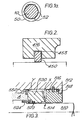
- the invention provides a washer or bush 50 between the seal element 16 and the main seal (not shown).
- the bush is retained within the gap between the back of the seal element 16 and the housing 12.
- the bush 50 allows some leak through the gap Y and/or is provided with scollops 52 to increase the leak so that in spite of the fact that the seal 14 closes quickly as fluid pressure builds up in region A, the pressure differential along the gap Y soon drops and appears instead along the gap X. Thus the normal running closing force on the seal element 16 soon returns to the same value as determined above where the bush 50 is not present.
- the washer or bush 50 not only serves the function described above but also serves to keep solids away from the seal faces 41, 42, firstly by virtue of its close fit on the shaft and secondly by its operation as a flinger when it occasionally rotates with the shaft.
- Fig. 2 shows a variation in the nature of the washer 450 is free but is captivated in a groove 453 formed in the seal element 416.
- the washer may be split and constructed from a resiliently deformable material such as rubber or PTFE to aid assembly.
- the split may be such that a significant gap Y as in Fig. 1 or scollops 52 as in Fig la are unnecessary.
- the bush 50 may likewise be constructed from PTFE or rubber.
Landscapes
- Engineering & Computer Science (AREA)
- General Engineering & Computer Science (AREA)
- Mechanical Engineering (AREA)
- Physics & Mathematics (AREA)
- Fluid Mechanics (AREA)
- Mechanical Sealing (AREA)
Applications Claiming Priority (2)
| Application Number | Priority Date | Filing Date | Title |
|---|---|---|---|
| GB8332074 | 1983-12-01 | ||
| GB838332074A GB8332074D0 (en) | 1983-12-01 | 1983-12-01 | Backup seal |
Publications (2)
| Publication Number | Publication Date |
|---|---|
| EP0149895A1 true EP0149895A1 (fr) | 1985-07-31 |
| EP0149895B1 EP0149895B1 (fr) | 1988-05-11 |
Family
ID=10552664
Family Applications (1)
| Application Number | Title | Priority Date | Filing Date |
|---|---|---|---|
| EP84308330A Expired EP0149895B1 (fr) | 1983-12-01 | 1984-11-30 | Joint d'étanchéité de réserve |
Country Status (4)
| Country | Link |
|---|---|
| US (1) | US4552368A (fr) |
| EP (1) | EP0149895B1 (fr) |
| DE (1) | DE3471147D1 (fr) |
| GB (1) | GB8332074D0 (fr) |
Cited By (2)
| Publication number | Priority date | Publication date | Assignee | Title |
|---|---|---|---|---|
| EP0302386A3 (fr) * | 1987-08-03 | 1991-04-17 | FRAU S.p.A. | Séparateur centrifuge à conduits axiaux d'entrée et de sortie |
| CN104214348A (zh) * | 2014-10-08 | 2014-12-17 | 江苏大唐国际吕四港发电有限责任公司 | 一种用于减速机的轴封结构 |
Families Citing this family (23)
| Publication number | Priority date | Publication date | Assignee | Title |
|---|---|---|---|---|
| US4662657A (en) * | 1985-08-30 | 1987-05-05 | Foster-Miller, Inc. | Flow system |
| DE8626535U1 (de) * | 1986-10-03 | 1987-11-05 | Carl Hurth Maschinen- und Zahnradfabrik GmbH & Co, 80809 München | Getriebe und dgl. Vorrichtung |
| US4936821A (en) * | 1986-11-05 | 1990-06-26 | Frau S.P.A. | Centrifugal separator with rotating seals on the fixed upper head |
| US4804194A (en) * | 1987-10-15 | 1989-02-14 | Bki/Ip International, Inc. | Mechanical seal lubrication improvement |
| DE3828833A1 (de) * | 1988-08-25 | 1990-03-01 | Mtu Muenchen Gmbh | Einrichtung zur abdichtung von durch medien, wie fluessigkeiten und/oder gasen, unterschiedlichen druckes beaufschlagten raeumen, insbesondere fuer turbomaschinen |
| GB2232728B (en) * | 1989-06-06 | 1992-12-09 | Crane John Uk Ltd | Mechanical face seals |
| DE4005427C1 (fr) * | 1990-02-21 | 1991-07-25 | Mannesmann Ag, 4000 Duesseldorf, De | |
| DE4005428A1 (de) * | 1990-02-21 | 1991-08-22 | Mannesmann Ag | Sperrfluessigkeits-dichtungsanordnung bei einem turboverdichter |
| US5174584A (en) * | 1991-07-15 | 1992-12-29 | General Electric Company | Fluid bearing face seal for gas turbine engines |
| US5169159A (en) * | 1991-09-30 | 1992-12-08 | General Electric Company | Effective sealing device for engine flowpath |
| US5299813A (en) * | 1991-12-20 | 1994-04-05 | Ingersoll-Dresser Pump Company | Floating seal ring |
| US5292138A (en) * | 1992-09-21 | 1994-03-08 | General Elecric Company | Rotor to rotor split ring seal |
| US5499824A (en) * | 1994-03-29 | 1996-03-19 | Georgia Tech Research Corporation | Mechanical seal with compliant face |
| US5593232A (en) * | 1995-11-22 | 1997-01-14 | Dresser-Rand Company | Integral pivot pad bushing seal bearing |
| DE10013154A1 (de) * | 2000-03-17 | 2001-09-20 | Ksb Ag | Wellenabdichtung |
| US7997583B2 (en) * | 2005-11-08 | 2011-08-16 | Eagle Industry Co., Ltd. | Mechanical sealing device |
| US20080003099A1 (en) * | 2006-06-30 | 2008-01-03 | Honeywell International, Inc. | Closed bias air film riding seal in event of housing breach for shared engine lubrication accessory gearboxes |
| US8181966B2 (en) | 2009-01-12 | 2012-05-22 | Kaydon Ring & Seal, Inc. | Gas seal for aerospace engines and the like |
| WO2011094134A2 (fr) * | 2010-01-27 | 2011-08-04 | Halliburton Energy Services, Inc. | Dispositif de mesure optique |
| JP7350447B2 (ja) * | 2019-12-09 | 2023-09-26 | イーグル工業株式会社 | メカニカルシール |
| JP7350446B2 (ja) * | 2019-12-09 | 2023-09-26 | イーグル工業株式会社 | メカニカルシール |
| WO2021230909A1 (fr) * | 2020-05-11 | 2021-11-18 | Danfoss A/S | Joint annulaire flottant pour compresseur frigorifique |
| EP4056876A1 (fr) * | 2021-03-09 | 2022-09-14 | Flender GmbH | Dispositif de transmission doté d'une douille flottante pour un moyen d'alimentation entre les composants d'un train épicycloïdal |
Citations (3)
| Publication number | Priority date | Publication date | Assignee | Title |
|---|---|---|---|---|
| DD56415A (fr) * | ||||
| DE2659880A1 (de) * | 1976-08-19 | 1978-02-23 | Flexibox Gmbh | Doppeltwirkende gleitringdichtung mit haupt- und reservedichtung |
| GB2076907A (en) * | 1980-05-31 | 1981-12-09 | Schubert & Salzer Maschinen | Shaft seals |
Family Cites Families (7)
| Publication number | Priority date | Publication date | Assignee | Title |
|---|---|---|---|---|
| US3090627A (en) * | 1959-12-21 | 1963-05-21 | Crane Packing Co | Tandem seal |
| GB941141A (en) * | 1961-05-09 | 1963-11-06 | James Stephens | Improvements in or relating to fluid-pressure seals for rotary members |
| US3144253A (en) * | 1961-11-06 | 1964-08-11 | Garlock Inc | Balanced mechanical seal |
| US3291491A (en) * | 1966-01-28 | 1966-12-13 | Watt V Smith | Submarine shaft seal and thrust compensator |
| DE2156953C3 (de) * | 1971-11-17 | 1974-10-10 | Klein, Schanzlin & Becker Ag, 6710 Frankenthal | Wellenabdichtung für Reaktorumwälzpumpen |
| SE417632B (sv) * | 1977-05-02 | 1981-03-30 | Sunds Defibrator | Tetningsanordning for axlar |
| DE2844945A1 (de) * | 1978-10-16 | 1980-04-30 | Burgmann Dichtungswerk Feodor | Wellendichtung |
-
1983
- 1983-12-01 GB GB838332074A patent/GB8332074D0/en active Pending
-
1984
- 1984-11-30 DE DE8484308330T patent/DE3471147D1/de not_active Expired
- 1984-11-30 EP EP84308330A patent/EP0149895B1/fr not_active Expired
- 1984-11-30 US US06/676,857 patent/US4552368A/en not_active Expired - Lifetime
Patent Citations (3)
| Publication number | Priority date | Publication date | Assignee | Title |
|---|---|---|---|---|
| DD56415A (fr) * | ||||
| DE2659880A1 (de) * | 1976-08-19 | 1978-02-23 | Flexibox Gmbh | Doppeltwirkende gleitringdichtung mit haupt- und reservedichtung |
| GB2076907A (en) * | 1980-05-31 | 1981-12-09 | Schubert & Salzer Maschinen | Shaft seals |
Non-Patent Citations (1)
| Title |
|---|
| K. TRUTNOVSKY: "Berührungsdichtungen an ruhenden und bewegten Maschinenteilen", 2nd edition, 1975, pages 209-211, Springer-Verlag, Berlin, DE; * |
Cited By (2)
| Publication number | Priority date | Publication date | Assignee | Title |
|---|---|---|---|---|
| EP0302386A3 (fr) * | 1987-08-03 | 1991-04-17 | FRAU S.p.A. | Séparateur centrifuge à conduits axiaux d'entrée et de sortie |
| CN104214348A (zh) * | 2014-10-08 | 2014-12-17 | 江苏大唐国际吕四港发电有限责任公司 | 一种用于减速机的轴封结构 |
Also Published As
| Publication number | Publication date |
|---|---|
| DE3471147D1 (en) | 1988-06-16 |
| GB8332074D0 (en) | 1984-01-11 |
| US4552368A (en) | 1985-11-12 |
| EP0149895B1 (fr) | 1988-05-11 |
Similar Documents
| Publication | Publication Date | Title |
|---|---|---|
| US4552368A (en) | Backup seal with bush in form of radially floating washer | |
| US4290611A (en) | High pressure upstream pumping seal combination | |
| US4659092A (en) | Mechanical seals | |
| US4305592A (en) | Gas seal bushing | |
| US5217233A (en) | Spiral groove seal system for sealing a high pressure gas | |
| US3088744A (en) | Submarine propeller shaft seal | |
| US4658847A (en) | Bimetallic C-ring seal | |
| US4257617A (en) | Shaft seal assembly | |
| US3675933A (en) | Seal with installed space parts | |
| US4304409A (en) | Sealing assembly | |
| US3147013A (en) | Dry gas seal | |
| US9803752B2 (en) | Seal assembly | |
| US3360272A (en) | Pressure staging mechanical seal | |
| US6142729A (en) | Sealing device for a turbomachine bearing chamber | |
| US3806135A (en) | Cooling seal | |
| US20020020967A1 (en) | Fail safe l-shaped spring carrier for gas seals | |
| US5409240A (en) | Seal with self-lubricating contact surface | |
| US4494760A (en) | Pressure balanced floating seal | |
| US3227463A (en) | Mechanical seal | |
| US3617068A (en) | Floating ring seal for rotating shafts | |
| US2999702A (en) | Shaft seal with positive automatic shut-down feature | |
| US10054226B1 (en) | Mechanical sealing system | |
| DE69618355T2 (de) | Wellendichtung | |
| US4192559A (en) | Rotary union | |
| US3606350A (en) | Hydrostatic shaft seal |
Legal Events
| Date | Code | Title | Description |
|---|---|---|---|
| PUAI | Public reference made under article 153(3) epc to a published international application that has entered the european phase |
Free format text: ORIGINAL CODE: 0009012 |
|
| AK | Designated contracting states |
Designated state(s): BE DE FR GB IT NL SE |
|
| 17P | Request for examination filed |
Effective date: 19851101 |
|
| 17Q | First examination report despatched |
Effective date: 19861021 |
|
| GRAA | (expected) grant |
Free format text: ORIGINAL CODE: 0009210 |
|
| AK | Designated contracting states |
Kind code of ref document: B1 Designated state(s): BE DE FR GB IT NL SE |
|
| ITF | It: translation for a ep patent filed | ||
| REF | Corresponds to: |
Ref document number: 3471147 Country of ref document: DE Date of ref document: 19880616 |
|
| ET | Fr: translation filed | ||
| PLBE | No opposition filed within time limit |
Free format text: ORIGINAL CODE: 0009261 |
|
| STAA | Information on the status of an ep patent application or granted ep patent |
Free format text: STATUS: NO OPPOSITION FILED WITHIN TIME LIMIT |
|
| 26N | No opposition filed | ||
| ITTA | It: last paid annual fee | ||
| EAL | Se: european patent in force in sweden |
Ref document number: 84308330.4 |
|
| REG | Reference to a national code |
Ref country code: GB Ref legal event code: IF02 |
|
| PGFP | Annual fee paid to national office [announced via postgrant information from national office to epo] |
Ref country code: SE Payment date: 20021106 Year of fee payment: 19 |
|
| PGFP | Annual fee paid to national office [announced via postgrant information from national office to epo] |
Ref country code: FR Payment date: 20021108 Year of fee payment: 19 |
|
| PGFP | Annual fee paid to national office [announced via postgrant information from national office to epo] |
Ref country code: GB Payment date: 20021127 Year of fee payment: 19 |
|
| PGFP | Annual fee paid to national office [announced via postgrant information from national office to epo] |
Ref country code: NL Payment date: 20021129 Year of fee payment: 19 |
|
| PGFP | Annual fee paid to national office [announced via postgrant information from national office to epo] |
Ref country code: DE Payment date: 20021205 Year of fee payment: 19 |
|
| PGFP | Annual fee paid to national office [announced via postgrant information from national office to epo] |
Ref country code: BE Payment date: 20030117 Year of fee payment: 19 |
|
| PG25 | Lapsed in a contracting state [announced via postgrant information from national office to epo] |
Ref country code: GB Free format text: LAPSE BECAUSE OF NON-PAYMENT OF DUE FEES Effective date: 20031130 Ref country code: BE Free format text: LAPSE BECAUSE OF NON-PAYMENT OF DUE FEES Effective date: 20031130 |
|
| PG25 | Lapsed in a contracting state [announced via postgrant information from national office to epo] |
Ref country code: SE Free format text: LAPSE BECAUSE OF NON-PAYMENT OF DUE FEES Effective date: 20031201 |
|
| BERE | Be: lapsed |
Owner name: *FLEXIBOX LTD Effective date: 20031130 |
|
| PG25 | Lapsed in a contracting state [announced via postgrant information from national office to epo] |
Ref country code: NL Free format text: LAPSE BECAUSE OF NON-PAYMENT OF DUE FEES Effective date: 20040601 |
|
| PG25 | Lapsed in a contracting state [announced via postgrant information from national office to epo] |
Ref country code: DE Free format text: LAPSE BECAUSE OF NON-PAYMENT OF DUE FEES Effective date: 20040602 |
|
| GBPC | Gb: european patent ceased through non-payment of renewal fee |
Effective date: 20031130 |
|
| PG25 | Lapsed in a contracting state [announced via postgrant information from national office to epo] |
Ref country code: FR Free format text: LAPSE BECAUSE OF NON-PAYMENT OF DUE FEES Effective date: 20040730 |
|
| NLV4 | Nl: lapsed or anulled due to non-payment of the annual fee |
Effective date: 20040601 |
|
| EUG | Se: european patent has lapsed | ||
| REG | Reference to a national code |
Ref country code: FR Ref legal event code: ST |