EP0150292A2 - Dispositif pour le remplissage dosé d'un matériau très visqueux - Google Patents
Dispositif pour le remplissage dosé d'un matériau très visqueux Download PDFInfo
- Publication number
- EP0150292A2 EP0150292A2 EP84113761A EP84113761A EP0150292A2 EP 0150292 A2 EP0150292 A2 EP 0150292A2 EP 84113761 A EP84113761 A EP 84113761A EP 84113761 A EP84113761 A EP 84113761A EP 0150292 A2 EP0150292 A2 EP 0150292A2
- Authority
- EP
- European Patent Office
- Prior art keywords
- filling
- tube
- film tube
- film
- transport
- Prior art date
- Legal status (The legal status is an assumption and is not a legal conclusion. Google has not performed a legal analysis and makes no representation as to the accuracy of the status listed.)
- Granted
Links
Images


Classifications
-
- B—PERFORMING OPERATIONS; TRANSPORTING
- B65—CONVEYING; PACKING; STORING; HANDLING THIN OR FILAMENTARY MATERIAL
- B65B—MACHINES, APPARATUS OR DEVICES FOR, OR METHODS OF, PACKAGING ARTICLES OR MATERIALS; UNPACKING
- B65B3/00—Packaging plastic material, semiliquids, liquids or mixed solids and liquids, in individual containers or receptacles, e.g. bags, sacks, boxes, cartons, cans, or jars
- B65B3/26—Methods or devices for controlling the quantity of the material fed or filled
- B65B3/30—Methods or devices for controlling the quantity of the material fed or filled by volumetric measurement
- B65B3/32—Methods or devices for controlling the quantity of the material fed or filled by volumetric measurement by pistons co-operating with measuring chambers
-
- B—PERFORMING OPERATIONS; TRANSPORTING
- B65—CONVEYING; PACKING; STORING; HANDLING THIN OR FILAMENTARY MATERIAL
- B65B—MACHINES, APPARATUS OR DEVICES FOR, OR METHODS OF, PACKAGING ARTICLES OR MATERIALS; UNPACKING
- B65B9/00—Enclosing successive articles, or quantities of material, e.g. liquids or semiliquids, in flat, folded, or tubular webs of flexible sheet material; Subdividing filled flexible tubes to form packages
- B65B9/10—Enclosing successive articles, or quantities of material, in preformed tubular webs, or in webs formed into tubes around filling nozzles, e.g. extruded tubular webs
- B65B9/20—Enclosing successive articles, or quantities of material, in preformed tubular webs, or in webs formed into tubes around filling nozzles, e.g. extruded tubular webs the webs being formed into tubes in situ around the filling nozzles
- B65B9/2014—Tube advancing means
- B65B9/2028—Rollers or belts
-
- B—PERFORMING OPERATIONS; TRANSPORTING
- B65—CONVEYING; PACKING; STORING; HANDLING THIN OR FILAMENTARY MATERIAL
- B65B—MACHINES, APPARATUS OR DEVICES FOR, OR METHODS OF, PACKAGING ARTICLES OR MATERIALS; UNPACKING
- B65B9/00—Enclosing successive articles, or quantities of material, e.g. liquids or semiliquids, in flat, folded, or tubular webs of flexible sheet material; Subdividing filled flexible tubes to form packages
- B65B9/10—Enclosing successive articles, or quantities of material, in preformed tubular webs, or in webs formed into tubes around filling nozzles, e.g. extruded tubular webs
- B65B9/20—Enclosing successive articles, or quantities of material, in preformed tubular webs, or in webs formed into tubes around filling nozzles, e.g. extruded tubular webs the webs being formed into tubes in situ around the filling nozzles
- B65B9/213—Enclosing successive articles, or quantities of material, in preformed tubular webs, or in webs formed into tubes around filling nozzles, e.g. extruded tubular webs the webs being formed into tubes in situ around the filling nozzles the web having intermittent motion
-
- B—PERFORMING OPERATIONS; TRANSPORTING
- B65—CONVEYING; PACKING; STORING; HANDLING THIN OR FILAMENTARY MATERIAL
- B65B—MACHINES, APPARATUS OR DEVICES FOR, OR METHODS OF, PACKAGING ARTICLES OR MATERIALS; UNPACKING
- B65B9/00—Enclosing successive articles, or quantities of material, e.g. liquids or semiliquids, in flat, folded, or tubular webs of flexible sheet material; Subdividing filled flexible tubes to form packages
- B65B9/10—Enclosing successive articles, or quantities of material, in preformed tubular webs, or in webs formed into tubes around filling nozzles, e.g. extruded tubular webs
- B65B9/20—Enclosing successive articles, or quantities of material, in preformed tubular webs, or in webs formed into tubes around filling nozzles, e.g. extruded tubular webs the webs being formed into tubes in situ around the filling nozzles
- B65B9/2007—Means for stripping or squeezing filled tubes prior to sealing to remove air or products from sealing area
Definitions
- the invention relates to a device according to the preamble of claim 1.
- the invention has for its object to provide a device of the generic type, by means of which a metered filling of such highly viscous materials in tubular bags is possible.
- the material is metered through a filling tube which is surrounded by a film tube forming device in which a film tube is continuously formed.
- the film tube is transported in accordance with the metered amount of material supplied, the sensors ensuring that the transport route of the film tube always corresponds exactly to the metered amount of material supplied and filled.
- the film tube is welded directly above the level of the filling, so that on the one hand there are practically no bubbles in the finished tubular bag, and on the other hand that no material gets into the cross-weld seam, which reduces its strength would, or even create a direct connection to the outside air.
- a visual inspection of the filling and closing process is no longer necessary.
- the filling of the film tube which is closed at its lower end by a transverse weld seam, begins at its bottom. The strand of material is cut off without overrun.
- the further embodiment according to claim 2 ensures that the amount of material actually conveyed by the metering device is recorded in a structurally very simple manner, so that an actual value is present with respect to the amount of material conveyed, which is used as a setpoint for the transport of the film tube.
- the measures according to claim 3 ensure that the material strand emerging from the filling tube is cut in a very simple manner without the dosage being influenced or impaired in any way.
- the measures according to the invention enable the use of the existing means for supplying an inert gas in the area where the material emerges from the filling tube, so that there is always a dry inert gas atmosphere in the film tube.
- Claim 5 represents a particularly simple and effective transport device for slip-free defined transport of the film tube.
- the embodiment according to claim 6 is provided, according to which the cutting wire and the associated outside of the valve are practically flush.
- the design of the transverse welding device according to claim 7 ensures that the film tube is first closed immediately adjacent to the level of the filling and only then is welded.
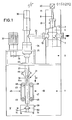
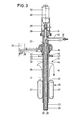
- the device shown in FIG. 1 has a machine frame 1 which has a tower-like structure 2 which carries a metering device 3, which is shown in detail in FIG. 2.
- the metering device 3 has a metering cylinder 4 in which a metering piston 5 is floatingly mounted.
- a feed line 6 opens into the lower region of the metering cylinder 4, through which material to be metered is fed by means of a pump (not shown).
- a rotary-plug 7 is disposed, each of which is rotatable about its coincident with the central longitudinal axis 8 of the metering cylinder 4 axis 18o 0th
- its passage channel 9 can either connect the feed line 6 to the interior of the metering cylinder 4 or the latter to a discharge line lo, which is arranged in alignment with the feed line 6.
- the supply line 6 and the discharge pipe 1 0 are mounted directly on the housing 11 of the rotary plug. 7
- the cylinder 12 of a hydraulic piston-cylinder drive 13 is arranged in alignment with its axis 8. Its piston rod 14 is also provided with a length-adjustable delivery rod 15 which bears against the top of the metering piston 5, but is not connected to it.
- the piston 16 of the drive 13 is still with a transmission line which is led upwards out of the cylinder 12 rod 17 coupled, which is connected to an encoder 2o. On the basis of the coupling described, this transmitter 2o emits a signal which represents the exact position of the piston 16 with the piston rod 14 and thus of the metering piston 5 - when this is applied to the delivery rod 15.
- a filling device 21 is also arranged on the machine frame 1, the central longitudinal axis 22 of which runs vertically in the same way as the axis 8.
- This filling device 21 has a filling pipe 23 concentric to the axis 22, which is connected via a feed pipe 24 to the discharge line 10 of the metering device 3, so that exactly the amount of material dispensed metered by the metering device 3 reaches the filling pipe 23.
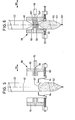
- the filler tube 23 has at its lower end a nozzle 25 which can be closed by means of a valve 26, the plunger 27 of which is connected to a rod 28, which in turn is connected to the piston rod 29 of an actuator 3o designed as a pneumatic piston-cylinder drive for the Valve 26 is connected.
- the rod 28 is mounted in an axially parallel manner to be displaceably sealed in a housing 31, into which the feed connector 24 also opens and from which the elongated filling tube 23 opens.
- the entire arrangement is arranged concentrically with the axis 22.
- the material to be conveyed is conveyed through the annular space 32 between the plunger 27 and the filling pipe 23.
- a rotary tube 33 rotatable about the axis 22 is arranged concentrically around the filling tube 23.
- This rotary tube is rotatably supported at its upper end in a bearing housing 34 which is supported in a holding stand 35 of the machine frame 1.
- the upper part of the rotary tube 33 is driven directly below the bearing housing 34 by means of a V-belt drive 36 by an electric drive motor 37, which is designed as a clutch-brake motor.
- This drive motor 37 is also arranged on the support stand 35.
- a cutting wire 38 which extends diametrically over the end face thereof and which is likewise arranged immediately below, that is to say in front of the valve 26 and which, at the end of a filling process, the strand consisting of pasty material with the rotary tube 33 being driven accordingly cuts through.
- a material cutting device is thus created by the rotary tube 33 with the cutting wire 38.
- a format tube 39 is arranged, which is fixed to the machine frame 1 by means of an upper holding flange 4o.
- An annular gap between the format tube 39 and the rotary tube 33 serves as a channel 41 for an inert gas which can be fed to the channel 41 via a connection 42.
- This connection 42 is formed at the upper end of the channel 41, specifically in the holding flange 4o.
- the channel 41 is sealed directly above by means of a sealing flange 43.
- a format shoulder 44 surrounding the format tube 39, by means of which a film web is formed in a generally known manner to form a film tube 45 surrounding the format tube 39.
- This film tube 45 is longitudinally welded by means of a generally customary welding device 44a, which is only indicated in the drawing.
- the film tube is transported downwards by means of a transport device 46, which has two endless conveyor belts 47 lying diametrically opposite one another on the format tube 39, which are deflected via rollers 48, 49, of which the lower rollers 49 can each be driven by a drive motor (not shown) via a shaft 50 are.
- the drive thus takes place in the transport direction 51.
- a transmitter 52 also belongs to the transport device 46 and detects the transport of the film tube 45 in the transport direction 51.
- This encoder 52 is coupled to the shaft 5o so that it can be driven in rotation, so that the feed of the transport device 46 simultaneously delivers a 14ass for the transport of the film tube 45.
- the format tube 39 ends somewhat above the valve 26 or the separating device.
- a welding device 59 is attached to the machine frame 1, which is also arranged in alignment with the axis 22.
- This welding device 59 has two mutually movable welding jaws 6 0 , 61, by means of which the film tube is cross-welded and cut directly above the filling 62, so that filled tubular bags 63 are formed.
- Each welding jaw is provided with a pair of pliers 64 which is mounted on the respective welding jaw in the displacement direction 65. It is guided against a compression spring 66 against the closing direction of the respective welding jaw, so that when the welding jaws 6 0 , 61 are closed, the two pliers parts 64, which then act together as pliers, compress the film tube 45 immediately above the mirror 67 of the filling 62, so that - as can be seen in FIG. 6 - it encloses the filling 62 without spaces. The film tube 45 is then welded immediately above these pliers parts 64. In the final phase of the welding jaws 6 0 , 61 being brought together, the pliers parts 64 are displaced relative to the respective welding jaw 6 0 or 61.
- a separating knife 68 is slidably mounted, which at the end of the welding process, before opening the welding jaws 6 0 , 61, cuts the transverse weld seam 69 in the center, so that, on the one hand, a filled tubular bag 63 falls down, the bottom with a transverse weld seam 69 'and closed at the top with a transverse weld seam 69 ".
- the upper part of the central transverse weld seam 69 in turn already forms the lower transverse weld seam 69" of the next tubular bag to be filled and closed.
- the cutting knife 68 is actuated by means of a pneumatic piston-cylinder drive 7o.
- the welding jaws 6 0 , 61 are guided on guide rods 71 attached to the machine frame 1. They are driven by piston-cylinder drives located in the machine frame and not visible in the drawing.
- the film web from which the film tube 45 is formed consists of a thermoplastic, ie weldable plastic, or of an aluminum foil coated with thermoplastic, ie weldable plastic.
- thermoplastic ie weldable plastic
- sealing compounds are filled, i.e. highly viscous materials, which already contain their hardener and harden under the influence of atmospheric humidity.
- Such sealing compounds mentioned here by way of example are widely used in practice as so-called permanently elastic sealing compounds.
- the drive 13 is pressurized via an unillustrated solenoid valve with pressure medium, which now dosed which is pressed material to be conveyed through the discharge pipe 1 is 0, the supply pipe 24 and the annular space 32 between the filling tube 23 and plunger 27 through the nozzle 25 with the valve open 26 .
- the amount squeezed out by the metering piston 5 is precisely detected by the transmitter 2o, which precisely detects the path of the metering piston 5 and thus the amount of material conveyed.
- the transport of the film tube 45 is detected by the encoder 52.
- the signals emitted by the transmitter 52 which are a measure of the transport path of the film tube 45, are used to control the drive for the transport device.
- the signals from the encoder 2 0 which represent the actual value of the metered conveyance of the material, give at the same time Setpoint for the transport of the film tube 45 before, the actual value is in turn detected by the encoder 52.
- the transport takes place the film tube offset in time relative to the induced by the dosing piston 5 filling process.
- the drive 13 of the metering device 3 is stopped and at the same time the rotary plug 7 is rotated again into the filling position shown in FIG. 2.
- the valve 26 is closed by appropriate actuation of the actuator 3o and the rotary tube 33 is rotated by the drive motor 37, so that the cutting wire 38 cuts the material strand without dripping on the outside of the valve 26.
- the transport device 46 continues to run until the transport path of the film tube 45 corresponds exactly to the amount of material supplied by the metering device 3, so that with this temporal offset of material conveyance on the one hand and film tube transport on the other hand the mirror 67 of the filling 62 is exactly in the area in which the pliers parts 64 clamp off the film tube 45, so that a bubble-free filling of the tube bag 63 subsequently produced in the manner already described is ensured.
- the constant supply of nitrogen as an inert gas ensures, on the one hand, that no air comes into contact with the materials to be filled during the filling process and that no bubbles are present in the tubular bag Air, but a neutral dry gas.
- the described sequence control of metering and film tube transport can ensure that filling is practically bubble-free on the one hand and that no material gets into the transverse weld seam 69 on the other hand.
Landscapes
- Engineering & Computer Science (AREA)
- Mechanical Engineering (AREA)
- Containers And Plastic Fillers For Packaging (AREA)
- Basic Packing Technique (AREA)
- Polymerisation Methods In General (AREA)
- Acyclic And Carbocyclic Compounds In Medicinal Compositions (AREA)
- Paints Or Removers (AREA)
- Polyurethanes Or Polyureas (AREA)
- Wrappers (AREA)
- Lubricants (AREA)
- Solid-Sorbent Or Filter-Aiding Compositions (AREA)
Priority Applications (1)
| Application Number | Priority Date | Filing Date | Title |
|---|---|---|---|
| AT84113761T ATE28736T1 (de) | 1984-01-24 | 1984-11-14 | Vorrichtung zum dosierten abfuellen von hochviskosem material. |
Applications Claiming Priority (2)
| Application Number | Priority Date | Filing Date | Title |
|---|---|---|---|
| DE19843402242 DE3402242A1 (de) | 1984-01-24 | 1984-01-24 | Vorrichtung zum dosierten abfuellen von hochviskosem material |
| DE3402242 | 1984-01-24 |
Publications (3)
| Publication Number | Publication Date |
|---|---|
| EP0150292A2 true EP0150292A2 (fr) | 1985-08-07 |
| EP0150292A3 EP0150292A3 (en) | 1985-08-21 |
| EP0150292B1 EP0150292B1 (fr) | 1987-08-05 |
Family
ID=6225699
Family Applications (1)
| Application Number | Title | Priority Date | Filing Date |
|---|---|---|---|
| EP84113761A Expired EP0150292B1 (fr) | 1984-01-24 | 1984-11-14 | Dispositif pour le remplissage dosé d'un matériau très visqueux |
Country Status (6)
| Country | Link |
|---|---|
| EP (1) | EP0150292B1 (fr) |
| JP (1) | JPS60158008A (fr) |
| AT (1) | ATE28736T1 (fr) |
| DE (2) | DE3402242A1 (fr) |
| DK (1) | DK155364C (fr) |
| ES (1) | ES282896Y (fr) |
Cited By (2)
| Publication number | Priority date | Publication date | Assignee | Title |
|---|---|---|---|---|
| WO1995019292A1 (fr) * | 1994-01-15 | 1995-07-20 | Knieriem Guenther | Dispositif pour la fabrication et le remplissage d'emballages tubulaires |
| CN109533423A (zh) * | 2018-11-28 | 2019-03-29 | 江苏恒耐炉料集团有限公司 | 一种浇注料分包封塑机 |
Families Citing this family (4)
| Publication number | Priority date | Publication date | Assignee | Title |
|---|---|---|---|---|
| JPH0755688B2 (ja) * | 1986-09-10 | 1995-06-14 | 呉羽化学工業株式会社 | 自動充填包装装置 |
| DE19631812A1 (de) * | 1996-08-07 | 1998-02-12 | Basf Lacke & Farben | Entnahmevorrichtung für Stoffproben |
| JP3560919B2 (ja) * | 2001-02-06 | 2004-09-02 | オリヒロエンジニアリング株式会社 | 包装袋の製造方法および縦型製袋充填機 |
| DE102016221895A1 (de) * | 2016-11-08 | 2018-05-09 | Brose Fahrzeugteile Gmbh & Co. Kommanditgesellschaft, Bamberg | Verfahren zur Abdichtung einer Sensorelektrode |
Family Cites Families (12)
| Publication number | Priority date | Publication date | Assignee | Title |
|---|---|---|---|---|
| DE1436003A1 (de) * | 1962-11-20 | 1969-02-13 | Hoefliger & Karg | Verfahren zum Fuellen von Schlauchbeuteln waehrend der Bewegung |
| FR1545970A (fr) * | 1966-11-09 | 1968-11-15 | Kalle Ag | Procédé et dispositif pour la production continue d'emballages en forme de boyaux |
| US3538676A (en) * | 1967-03-08 | 1970-11-10 | William R Runo | Packaging machine |
| BE786837A (fr) * | 1971-07-29 | 1973-01-29 | Bayer Ag | Colorants polyazoiques |
| AU465083B2 (en) * | 1972-05-24 | 1975-09-18 | The Procter & Gamble Company | Improved flavor and eating quality in formulated potato chips made from dehydrated potato flakes |
| DE2320699A1 (de) * | 1973-04-24 | 1974-11-21 | Scherico Ltd | Abfuellmaschine |
| DE2503547A1 (de) * | 1975-01-29 | 1976-08-05 | Jentsch Hans G | Verfahren und vorrichtung zum sterilen abfuellen von fluessigem, pulverfoermigem, granuloesem oder koernigem fuellgut in behaelter bzw. beutel aus siegelfaehigem material |
| JPS51150487A (en) * | 1975-06-19 | 1976-12-24 | Laurel Bank Mach Co Ltd | Device of automatically packaging coins |
| US4023327A (en) * | 1976-06-04 | 1977-05-17 | Package Machinery Company | Control system for package making machine |
| JPS533699A (en) * | 1976-06-30 | 1978-01-13 | Mitsubishi Chem Ind | Method of manufacturing temporaily burned powder of ferroodielectric ceramics |
| JPS5538207A (en) * | 1978-08-25 | 1980-03-17 | Jiyun Tanaka | Automatic liquiddmedicine partial packing device |
| US4391081A (en) * | 1980-09-08 | 1983-07-05 | Hayssen Manufacturing Company | Method of and apparatus for forming, filling and sealing packages |
-
1984
- 1984-01-24 DE DE19843402242 patent/DE3402242A1/de not_active Withdrawn
- 1984-11-14 DE DE8484113761T patent/DE3465175D1/de not_active Expired
- 1984-11-14 AT AT84113761T patent/ATE28736T1/de not_active IP Right Cessation
- 1984-11-14 EP EP84113761A patent/EP0150292B1/fr not_active Expired
- 1984-11-26 JP JP59248276A patent/JPS60158008A/ja active Pending
- 1984-11-26 ES ES1984282896U patent/ES282896Y/es not_active Expired
- 1984-11-28 DK DK564184A patent/DK155364C/da not_active IP Right Cessation
Cited By (2)
| Publication number | Priority date | Publication date | Assignee | Title |
|---|---|---|---|---|
| WO1995019292A1 (fr) * | 1994-01-15 | 1995-07-20 | Knieriem Guenther | Dispositif pour la fabrication et le remplissage d'emballages tubulaires |
| CN109533423A (zh) * | 2018-11-28 | 2019-03-29 | 江苏恒耐炉料集团有限公司 | 一种浇注料分包封塑机 |
Also Published As
| Publication number | Publication date |
|---|---|
| ES282896Y (es) | 1985-12-01 |
| DK155364C (da) | 1989-08-21 |
| ES282896U (es) | 1985-05-01 |
| DK564184A (da) | 1985-07-25 |
| DK155364B (da) | 1989-04-03 |
| ATE28736T1 (de) | 1987-08-15 |
| EP0150292B1 (fr) | 1987-08-05 |
| DK564184D0 (da) | 1984-11-28 |
| EP0150292A3 (en) | 1985-08-21 |
| DE3465175D1 (en) | 1987-09-10 |
| JPS60158008A (ja) | 1985-08-19 |
| DE3402242A1 (de) | 1985-07-25 |
Similar Documents
| Publication | Publication Date | Title |
|---|---|---|
| DE2946059C2 (de) | Vorrichtung zum Herstellen mit Flüssigkeit gefüllter Packungen | |
| DE69213337T2 (de) | Vorrichtung vom vertikalen Typ, zum Formen, Füllen und Schliessen von flexiblen Verpackungen | |
| DE1511496A1 (de) | System zur Herstellung fluessigkeitsgefuellter Pakete | |
| EP0621187B1 (fr) | Machine de fabrication de sachets plats disposée verticalement et à opération intermittente | |
| DE68902962T2 (de) | Verfahren zum vakuumverpacken von fluessigkeiten und pasten in weichen, mit abgabeventil oder -pumpe versehenen tuben und vorrichtung zur durchfuehrung dieses verfahrens. | |
| EP1918206B1 (fr) | Dispositif de remplissage et procédé de remplissage de produit de remplissage visqueux | |
| CH415425A (de) | Verfahren und Vorrichtung zur Herstellung von Packungen | |
| EP2483165A1 (fr) | Dispositif et procédé de formage, de remplissage et de fermeture de sachets pourvus d'un dispositif verseur | |
| DE19742213C2 (de) | Verfahren zum Verschließen von schlauch- oder beutelförmigen Verpackungshüllen und Verschließvorrichtung | |
| DE1511674A1 (de) | Verfahren und Vorrichtung zum kontinuierlichen Herstellen von Schlauchpackungen | |
| EP0150292B1 (fr) | Dispositif pour le remplissage dosé d'un matériau très visqueux | |
| DE1921234C3 (de) | Vorrichtung zur Herstellung von Verpackungen mit flachem Boden aus einem fortlaufenden Folienstreifen | |
| DE20320160U1 (de) | Formschulter, insbesondere für Schlauchbeutelmaschinen | |
| EP0240694A2 (fr) | Dispositif pour fabriquer des sacs d'emballage remplis avec un liquide | |
| DE1036154B (de) | Vorrichtung zum Verpacken von fluessigen bis pastenfoermigen Stoffen in Beuteln aus weichgestellter Kunststoffolie | |
| DE3335754A1 (de) | Verfahren und vorrichtung zum abpacken von losem fuellgut | |
| EP0204086A1 (fr) | Dispositif pour la production de portions d'une matière pâteuse | |
| EP0401510B1 (fr) | Dispositif pour remplir des emballages de produits pouvant s'écouler | |
| CH413706A (de) | Vorrichtung zum Öffnen und Schliessen der Quersiegelbacke und Gegenschiene in Verpackungsmaschinen | |
| DE3738178A1 (de) | Verfahren zum verpacken von verpackungsgut in verpackungsbeuteln unter verwendung einer schlauchfolie sowie vorrichtung zum durchfuehren dieses verfahrens | |
| DE4401031C1 (de) | Vorrichtung zum Herstellen und Befüllen von Schlauchbeutelpackungen | |
| DE69208461T2 (de) | Gerät zum Abgeben einer definierten Flüssigkeitsmenge | |
| EP0808772A1 (fr) | Procédé et appareil pour le thermoscellage de gaines tubulaires | |
| DE3007069C2 (de) | Vorrichtung zum dosierten Abfüllen einer zähviskosen Paste | |
| DE19731660C1 (de) | Vorrichtung zum Herstellen und Befüllen von Schlauchbeutelpackungen |
Legal Events
| Date | Code | Title | Description |
|---|---|---|---|
| PUAI | Public reference made under article 153(3) epc to a published international application that has entered the european phase |
Free format text: ORIGINAL CODE: 0009012 |
|
| PUAL | Search report despatched |
Free format text: ORIGINAL CODE: 0009013 |
|
| AK | Designated contracting states |
Designated state(s): AT BE CH DE FR GB IT LI NL SE |
|
| AK | Designated contracting states |
Designated state(s): AT BE CH DE FR GB IT LI NL SE |
|
| 17P | Request for examination filed |
Effective date: 19860103 |
|
| 17Q | First examination report despatched |
Effective date: 19860707 |
|
| GRAA | (expected) grant |
Free format text: ORIGINAL CODE: 0009210 |
|
| AK | Designated contracting states |
Kind code of ref document: B1 Designated state(s): AT BE CH DE FR GB IT LI NL SE |
|
| REF | Corresponds to: |
Ref document number: 28736 Country of ref document: AT Date of ref document: 19870815 Kind code of ref document: T |
|
| ITF | It: translation for a ep patent filed | ||
| REF | Corresponds to: |
Ref document number: 3465175 Country of ref document: DE Date of ref document: 19870910 |
|
| ET | Fr: translation filed | ||
| PLBE | No opposition filed within time limit |
Free format text: ORIGINAL CODE: 0009261 |
|
| STAA | Information on the status of an ep patent application or granted ep patent |
Free format text: STATUS: NO OPPOSITION FILED WITHIN TIME LIMIT |
|
| 26N | No opposition filed | ||
| PG25 | Lapsed in a contracting state [announced via postgrant information from national office to epo] |
Ref country code: SE Effective date: 19891115 |
|
| PGFP | Annual fee paid to national office [announced via postgrant information from national office to epo] |
Ref country code: CH Payment date: 19911004 Year of fee payment: 8 |
|
| PGFP | Annual fee paid to national office [announced via postgrant information from national office to epo] |
Ref country code: AT Payment date: 19911010 Year of fee payment: 8 |
|
| PGFP | Annual fee paid to national office [announced via postgrant information from national office to epo] |
Ref country code: GB Payment date: 19911030 Year of fee payment: 8 |
|
| PGFP | Annual fee paid to national office [announced via postgrant information from national office to epo] |
Ref country code: FR Payment date: 19911114 Year of fee payment: 8 |
|
| ITTA | It: last paid annual fee | ||
| PGFP | Annual fee paid to national office [announced via postgrant information from national office to epo] |
Ref country code: NL Payment date: 19911130 Year of fee payment: 8 |
|
| PGFP | Annual fee paid to national office [announced via postgrant information from national office to epo] |
Ref country code: BE Payment date: 19911206 Year of fee payment: 8 |
|
| PGFP | Annual fee paid to national office [announced via postgrant information from national office to epo] |
Ref country code: DE Payment date: 19920125 Year of fee payment: 8 |
|
| PG25 | Lapsed in a contracting state [announced via postgrant information from national office to epo] |
Ref country code: GB Effective date: 19921114 Ref country code: AT Effective date: 19921114 |
|
| PG25 | Lapsed in a contracting state [announced via postgrant information from national office to epo] |
Ref country code: LI Effective date: 19921130 Ref country code: CH Effective date: 19921130 Ref country code: BE Effective date: 19921130 |
|
| BERE | Be: lapsed |
Owner name: LUDWIG SCHWERDTEL G.M.B.H. Effective date: 19921130 |
|
| PG25 | Lapsed in a contracting state [announced via postgrant information from national office to epo] |
Ref country code: NL Effective date: 19930601 |
|
| GBPC | Gb: european patent ceased through non-payment of renewal fee |
Effective date: 19921114 |
|
| NLV4 | Nl: lapsed or anulled due to non-payment of the annual fee | ||
| PG25 | Lapsed in a contracting state [announced via postgrant information from national office to epo] |
Ref country code: FR Effective date: 19930730 |
|
| REG | Reference to a national code |
Ref country code: CH Ref legal event code: PL |
|
| PG25 | Lapsed in a contracting state [announced via postgrant information from national office to epo] |
Ref country code: DE Effective date: 19930803 |
|
| REG | Reference to a national code |
Ref country code: FR Ref legal event code: ST |
|
| EUG | Se: european patent has lapsed |
Ref document number: 84113761.5 Effective date: 19900705 |