EP0150510A2 - Fermeture d'enclenchement avec axe pivotant unique - Google Patents
Fermeture d'enclenchement avec axe pivotant unique Download PDFInfo
- Publication number
- EP0150510A2 EP0150510A2 EP84116495A EP84116495A EP0150510A2 EP 0150510 A2 EP0150510 A2 EP 0150510A2 EP 84116495 A EP84116495 A EP 84116495A EP 84116495 A EP84116495 A EP 84116495A EP 0150510 A2 EP0150510 A2 EP 0150510A2
- Authority
- EP
- European Patent Office
- Prior art keywords
- closure element
- accordance
- closure
- arm
- fastening device
- Prior art date
- Legal status (The legal status is an assumption and is not a legal conclusion. Google has not performed a legal analysis and makes no representation as to the accuracy of the status listed.)
- Granted
Links
Images



Classifications
-
- B—PERFORMING OPERATIONS; TRANSPORTING
- B65—CONVEYING; PACKING; STORING; HANDLING THIN OR FILAMENTARY MATERIAL
- B65D—CONTAINERS FOR STORAGE OR TRANSPORT OF ARTICLES OR MATERIALS, e.g. BAGS, BARRELS, BOTTLES, BOXES, CANS, CARTONS, CRATES, DRUMS, JARS, TANKS, HOPPERS, FORWARDING CONTAINERS; ACCESSORIES, CLOSURES, OR FITTINGS THEREFOR; PACKAGING ELEMENTS; PACKAGES
- B65D33/00—Details of, or accessories for, sacks or bags
- B65D33/16—End- or aperture-closing arrangements or devices
- B65D33/25—Riveting; Dovetailing; Screwing; using press buttons or slide fasteners
- B65D33/2508—Riveting; Dovetailing; Screwing; using press buttons or slide fasteners using slide fasteners with interlocking members having a substantially uniform section throughout the length of the fastener; Sliders therefor
- B65D33/2541—Riveting; Dovetailing; Screwing; using press buttons or slide fasteners using slide fasteners with interlocking members having a substantially uniform section throughout the length of the fastener; Sliders therefor characterised by the slide fastener, e.g. adapted to interlock with a sheet between the interlocking members having sections of particular shape
-
- A—HUMAN NECESSITIES
- A44—HABERDASHERY; JEWELLERY
- A44B—BUTTONS, PINS, BUCKLES, SLIDE FASTENERS, OR THE LIKE
- A44B19/00—Slide fasteners
- A44B19/10—Slide fasteners with a one-piece interlocking member on each stringer tape
- A44B19/16—Interlocking member having uniform section throughout the length of the stringer
Definitions
- This invention relates to an interlocking closure fastening device, and more particularly, to an interlocking closure fastening device comprising an omega-shaped closure element and a co-acting clamping closure element.
- closure fastening devices for use in connection with plastic bags and the like are known. Furthermore, manufacturing methods for closure fastening devices made of plastic material are generally well-known.
- a closure fastening device for use in connection with a flexible container should be relatively easy to open from the outside. but relatively difficult to open from the inside. Generally, such a container can be used with its interior either under relatively high pressure or under relatively low pressure. The closure fastening device should provide a satisfactory seal for either condition.
- the closure fastening device should be suitable for economical manufacturing and should be relatively simple in design.
- the design should provide for variations in order to meet different needs. For example, it may be desirable to have a closure fastening device which is relatively difficult to open both from the inside and the outside. In general, the closure fastening device, however, should always be relatively easy to close.
- the closure fastening device when employed with a container.
- the container may be made from a thermoplastic material and the closure device and sidewalls of the container can be made integrally by extrusion as a unitary piece or can be made as separate components which are subsequently permanently connected together.
- Typical resin materials employed for interlocking closure devices and container films have included polyethylene. polyvinyl chloride copolymers. and synthetic rubbers.
- none of these construction materials have sufficient thermal tolerance for many commercial uses.
- both occlusion and deocclusion of the interlocking closure device is generally difficult for the user when the device is made from resin materials having high temperature tolerances due to their associated high flexural moduli.
- the fastening device includes a first flexible closure element having a general omega shape comprising an apex portion, and a profile portion extending from the apex portion. said apex portion being generally flat or slightly arcuate, and said profile portion comprising two inwardly curved arm portions terminating in two outwardly facing, curvilinear hook portions.
- the closure device includes a second flexible closure element having a generally flat or slightly arcuate apex portion, and a profile portion extending from the apex portion.
- the profile portion of the second closure element comprises first and second generally parallel arm portions wherein one of the arm portions terminates in an inwardly curved hook portion, and the other arm portion curves slightly inward prior to terminating in an outwardly extending clamp portion.
- the first flexible closure element and the second flexible closure element are adapted to disengage and engage each other by means of a torquing action so as to form a straddling type of occlusion.
- the fastening device includes a first flexible closure element having a general omega shape comprising an apex portion, and a profile portion extending from the apex portion, said apex portion being generally flat or slightly arcuate, and said profile portion comprising two inwardly curved arm portions terminating in two outwardly curving hook portions.
- the closure device includes a second flexible closure element having a generally flat or slightly arcuate apex portion, and a profile portion extending from the apex portion.
- the profile portion of the second closure element comprises two outwardly curved arm portions wherein one of the arm portions terminates in an inwardly curved hook portion, and the other arm portion curves inwardly prior to terminating in a slightly outwardly curved hook portion.
- the first flexible closure element and the second flexible closure element are adapted to disengage and engage each other by means of a torquing action so as to form an overlapping type of occlusion.
- the profile portion of the second closure element comprises two outwardly curved arm portions wherein one of the arm portions terminates in an inwardly curved hook portion, and the other arm portion curves progressively inwardly as to make contact with one of the arm portions of the first closure element when the fastening device is occluded, prior to terminating in a slightly outwardly curved hook portion.
- the fastening device includes a first flexible closure element having a general omega shape comprising an apex portion, and a profile portion extending from the apex portion, said apex portion being generally flat or slightly arcuate, and said profile portion comprising two irwardly curved arm portions, an outwardly extending arm portion from each of said inwardly curved arm portions. each'of said outwardly extending arm portion terminating in an outwardly curved hook portion.
- the closure device includes a second flexible closure element having a generally flat or slightly arcuate apex portion, and a profile portion extending from the apex portion.
- the profile portion of the second closure element comprises one inwardly curved arm portion terminating in an inwardly curved hook portion, and one generally straight arm portion extending from said apex portion in a generally perpendicular direction therefrom.
- the first flexible closure element and the second flexible closure element are adapted to disengage and engage each other by means of a torquing action so as to form a straddling type of occlusion.
- the closure fastening device of the instant invention may be made from a thermoplastic material selected from the group consisting of polyolefins such as polyethylene, polypropylene, and polybutylene; polyamides such as nylon; or other thermoplastic materials, including combinations thereof.
- the closure fastening device is preferably made from a thermoplastic resin composition comprising polypropylene, or a mixture of polypropylene resin and ethylene-propylene-diene monomer elastomer. or a mixture of polypropylene resin and ethylene-propylene copolymer elastomer.
- the dimensions of the closure fastening device may vary in accordance with intended use. and depending upon the materials used in their manufacture because of the variations in physical properties, such as flexural moduli.
- the closure fastening device of this invention can be manufactured by known methods such as by extrusion, by the use of molds or other known methods of producing such devices.
- the closure fastening device can be manufactured as a strip for later attachment to a film or it can be manufactured integral with the film.
- the closure device can be manufactured with or without flanges on one or both of the closure elements, depending upon intended use or expected additional manufacturing operations.
- the closure elements can be connected to a container or to a film to be formed into a container by the use of many known methods.
- a thermoelectric device can be applied to a film opposite a closure element to cause a transfer of heat through the film to produce melting at the interface of the film and the closure element. After cooling, the interface region joins the film and the closure element.
- thermoelectric device can be heated by rotary discs, or resistance heated wires, or traveling heater bands, or the like.
- connection between the film and the closure element can also be established by the use of hot melt adhesives. or hot jets of air to the interface, or ultrasonic heating, or other known methods.
- the present closure fastening device can be made from a heat sealable material and then attached to a heat sealable film so that a container can be formed economically by heat sealing surfaces to form the container.
- the instant closure fastening device provides many advantages for consumers when used on containers. For instance, it is easy to close a container because the closure elements torque or twist with respect to each other from the deoccluded to the occluded position with little effort in spite of the high flexural moduli of the temperature resistant resins used.
- the action contrasts with prior art structures such as arrow type of closures where, in the female elements, the hooked sides have to be bent or otherwise distorted for occlusion or deocclusion.
- a base portion has to be bent to accomplish occlusion or deocclusion.
- still another structure made very stiff requires longitudinal displacement to a non-hooked end before the male and female elements can be pried apart by elastic bending of portions of each element.
- Fig. i is a cross-sectional view of one embodiment of the closure fastening device in accordance with this invention, in an occluded position.
- a first flexible closure element 10 having a general omega shape is connected to a flange portion 11 for use in connection to a thermoplastic film.
- Closure element 10 has an apex portion 12 which is typically flat or slightly arcuate, and extending from apex portion 12 is a profile portion which comprises two inwardly curved arm portions 13 and 13' which terminate in two outwardly curving hook portions 14 and 14'. respectively.
- a second flexible closure element 15 is shown connected to a flange portion 16. and it comprises an apex portion 17 which may have a flat or slightly arcuate configuration.
- a profile portion comprising two generally parallel arm portions 18 and 18'.
- Arm portion 18' terminates in an inwardly curved hook portion 19. whereas arm portion 18 curves slightly inwardly prior to terminating in an outwardly extending clamp portion 20.
- Fig. 1 when the closure fastening device is in an occluded position, hook portion 14' of closure element 10 and hook portion 19 of closure element 15 are interlocked, and arm portion 18 and clamp portion 20 of closure element 15 are in locked contact with arm portion 13 ot closure element 10. It can also be seen from Fig.
- closure element 10 and closure element 15 form a straddling occlusion wherein arm portion 18 and clamp portion 20 of closure element 15 are positioned between arm portions 13 and 13' of closure element 10.
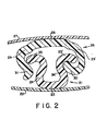
- Fig. 2 is a cross-sectional view of another embodiment of the closure fastening device in accordance with this invention, in an occluded position.
- the first flexible closure element 21 has a general omega shape, and that it may be connected to a flange portion 22 for connection to a thermoplastic film.
- Closure element 21 has an apex portion 23 which is slightly arcuate or generally flat. and extending from apex portion 23 is a profile portion which comprises two inwardly curved arm portions 24 and 24' which terminate in two outwardly curving hook portions 25 and 25'. respectively.
- a second flexible closure element 2b is shown connected to a flange portion 27. and it comprises an apex portion 28 which has a flat or slightly arcuate configuration.
- a profile portion comprising two outwardly curving arm portions 29 and 29'.
- Arm portion 29' terminates in an inwardly curved hook portion 30.
- arm portion 29 curves inwardly prior to terminating in a slightly outwardly curved hook portion 31.
- arm portion 29' terminating in inwardly curved hook portion 30 is adapted to engage in a hinging contact with arm portion 24' terminating in outwardly curving hook portion 25'.
- arm portion 24 terminating in outwardly curving hook portion 25 is adapted to engage in a clamping contact with arm portion 29 terminating in outwardly curved hook portion 31.
- closure element 21 and closure element 26 form an overlapping type of occlusion wherein hook portion 30 of closure element 26 overlaps hook portion 25' of closure element 21. and arm portion 29 and hook portion 31 of closure element 26 overlap hook portion 25 of closure element 21.
- Fig. 3 is a free body diagram showing a cross-sectional view of the closure fastening device shown in Fig. 2.
- the first flexible closure element 21 shown therein is the same as that shown in Fig. 2.
- the second flexible closure element 26 has been modified, whereby hook portion 31 may be positioned progressively laterally inward, as depicted by alternate hook portion 31 ' and alternate hook portion 31" shown in free body, toward arm portion 24 of closure element 21 until hook portion 31 makes contact with said arm portion 24 or is even deflected outwardly by arm portion 24.
- hook portion 25' and hook portion 30 act as a clamp in maintaining occlusion of the closure device.
- hook portion 25' and hook portion 30 provide a hinge action during deocclusion of closure element 26 and closure element 21 whereby hook portion 25' rotates with respect to hook portion 30 as shown in Fig. 4.
- Fig. 3-A is a cross-sectional view of the closure fastening device shown in Fig. 3 wherein the second flexible closure element is modified pursuant to alternate hook portion 31".
- the typical physical dimensions of a closure fastening device in accordance with Fig. 3 -A are as follows:
- A represents the height dimension of the closure fastening device in an occluded position as measured from the apex portion of the first closure element to the apex portion of the second closure element.
- B represents the height dimension of the second closure element as measured from the apex portion of the second closure element to the tip of the second arm portion of the second closure element.
- C represents the height dimension of the first closure element as measured from the apex portion of the first closure element to the highest part of the profile portion of the first closure element.
- R represents the width dimension of the second closure element as measured from the widest part of the first arm portion of the second closure element to the widest part of the second arm portion of the second closure element.
- S represents the width dimension of the first closure element as measured between the tips of the outwardly facing hook portions of the first closure element.
- Fig. 4 is a cross-sectional view of the closure fastening device shown in Fig. 2 in an occluded position, in a partially deoccluded position, and in a deoccluded position. It has been found that during occlusion and deocclusion of the closure fastening device of this invention, one or both of the closure elements of the fastening device experience a gradual twisting or torquing operation spread over a significant length of the closure on either side of the point of initial force application. The spreading action of this torque reduces stress levels, thereby reducing force. During deocclusion of the fastening device, this twisting or torquing operation continues until the hook portions of the closure elements have disengaged from each other.
- Fig. 4 shows in detail some of the operational steps during deocclusion of a closure fastening device as described with respect to Fig. 3 wherein the second closure element is modified pursuant to alternate hook portion 31'. More specifically, when said closure fastening device is in the occluded position, hook portion 31' of closure element 26 is in contact with arm portion 24 of closure element 21. or hook portion 25 of closure element 21 is in contact with arm portion 29 of closure element 26. Typically, for deocclusion of the closure fastening device, an external release force is exerted on hook portion 31' and arm portion 29 of closure element 26, and on hook portion 25 and arm portion 24 of closure element 21, to cause release of hook portion 31' and arm portion 29 of closure element 26, from hook portion 25 and arm portion 24 of closure element 21.
- the afore-mentioned parts of the fastening device are rotated over an arc of about 35° to a position generally designated as A, as shown by the arrows in Fig. 4.
- rotation of the closure elements is continued over an arc of between about 100° and 120° to a position generally designated as B, as shown by the arrows in Fig. 4.
- arm portion 24' and hook portion 25' of closure element 21. disengage from hook portion 3 0 of closure element 2 6 . while rotating around hook portion 30 of closure element 26 until the parts are separated from each other.
- closure element 21 and closure element 26 may be modified as described with respect to Fig. 5.
- Fig. 5 is shown the closure elements described with respect to Fig. 4 with the following modifications having been made thereto. More particularly, the inside radius of curvature of hook portion 30 is decreased.
- deocclusion of the closure fastening device after hook portion 31 ' and arm portion 29 of closure element 26 are released from hook portion 25 and arm portion 24 of closure element 21, continued rotation of the closure elements results in hook portion 30 of closure element 26 having a camming or leverage effect upon arm portion 24' and hook portion 15' of closure element 21 to provide release of these parts at an arc of about 75°.
- the contact point between hook portion 30 of closure element 26 and arm portion 24' of closure element 21 is generally designated in Fig. 5 as point L. and the contact point between hook portion 30 of closure element 26 and hook portion 25' of closure element 21 is generally shown therein as point M. It has been found that the aforedescribed closure elements provide deocclusion of the occluded fastening device more quickly by requiring a lesser amount of rotation of the closure elements without affecting good occlusion.
- Fig. 6 is a cross-sectional view of another embodiment of the closure fastening device in accordance with this invention in a deoccluded position.
- the closure fastening device includes a first flexible closure element 40 having a general omega shape, and comprises a generally flat or slightly arcuate apex portion 41 and a profile portion extending from the apex portion.
- the profile portion comprises two inwardly curved arm portions 42 and 42', respectively, with arm portions 43 and 43' outwardly extending from said inwardly curved arm portions, respectively, and with said outwardly extending arm portions terminating in outwardly curving hook portions 44 and 44'. respectively.
- the closure fastening device includes a second flexible closure element 45 having a generally flat or slightly arcuate apex portion 46 and a profile portion extending from said apex portion.
- the profile portion of said second closure element comprises one inwardly curved arm portion 47 terminating in an inwardly curved hook portion 48. and one generally straight arm portion 49 extending in a generally perpendicular direction from said apex portion.
- Fig. 7 is a cross-sectional view of the closure fastening device described with respect to Fig. 6. but shown herein in an occluded position. It can be seen from Fig. 7 that when the instant closure fastening device is in an occluded position. arm portion 49 of closure element 45 is located between and in contact with outwardly extending arm portions 43 and 43' of closure element 40, and hook portion 44 of closure element 40 is interlocked with hook portion 48 of closure element 45. It can also be seen from Fig. 7 that arm portion 43 terminating in outwardly curving hook portion 44 is adapted to engage in a hinging contact with arm portion 47 terminating in inwardly curved hook portion 48.
- the closure fastening device of this invention provides a fastening device which is relatively easy to deocclude or open from the outside of the container, but which is relatively difficult to deocclude or open from the inside of the container. Accordingly, when thus employed on a container, the closure fastening device provides improved security to contents stored in said container.
- Fig. 8 is a cross-sectional view of the closure fastening device shown in Fig. 7 in a partially deoccluded position such as during deocclusion of the fastening device. It may be seen from Fig. 8 that during deocclusion of closure element 45 and closure element 40, arm portions 43 and 43' of closure element 40 first separate from arm portion 49 of closure element 45. As closure element 40 and closure element 45 are further rotated with respect to each other for separation. hook portion 44 of closure element 40 will rotate around and then slip away from hook portion 48 of closure element 45, thereby resulting in their separation and in the complete deocclusion of the closure fastening device.
- closure fastening devices of this invention were evaluated for opening loads for comparison with several commercial plastic container products having a closure fastening device.
- each occluded 15,24 cm closure fastening device was cut into a(six inch) long sample.
- the closure fastening device samples 2,54 cm were tested by attaching a piece of (one inch) wide scotch tape doubled over to grip the inside and/or outside flange portions of the fastening device. Each sample was tested independently as described herein.
- the male portion of the closure fastening device was mounted in the upper jaw, and the female portion of the closure fastening device was mounted in the lower jaw. of an Instron® tensile tester.
- the force required to deocclude the closure fastening device was recorded on a strip chart recorder as the maximum force registered. The average value was listed as the average of five test specimens and it was recorded as release force. The 50,8 cm jaw separation (deocclusion) rate was (20 inches) per 9,07 kg minute and the full scale load was (20 pounds). Each of 5 identical samples was reoccluded and retested for a total of 5 tests. The value reported was thus the average of 25 tests for each sample.
- the Instron instrument was a tensile tester Model No. 1130, using a "B" load cell with a zero to 9,07 kg (20 pound)range.
- the Instron tester is initially calibrated in the following manner.
- the pen and chart recorder are turned on.
- the zero button is pressed and held. and the zero adjust knob is positioned for a 0.00 reading on the recorder.
- the zero button is then released.
- the range switch is then turned to the setting of 1 on its 1. 2. 5. 10. 20 scale.
- the coarse balance control is turned so that if the pen is all the way over to the left. it starts coming towards zero on the right.
- the coarse balance control is left at this position.
- the fine balance control iis turned so that the p en is at a setting of 0.00.
- A(20 pound)weight is placed in the upper jaw of the Instron instrument and the calibration control is adjusted for a full-scale recorder reading. After removing the weight, the recorder should again read 0.00. The zero button is pressed and held, and the recorder should again read 0.00.
- the closure fastening devices of sample 4 and sample 5 were made with a thermoplastic resin composition comprising about 84 percent by weight of polypropylene homopolymer. about 15 percent by weight of an ethylene-propylene-diene monomer elastomer, and about 1 percent by weight of a slip agent, all weight percentages being based on the weight of the fastening device.
- external release forces is meant the forces required to deocclude the closure fastening device from the outside portion of a container.
- internal release forces is meant the forces required to deocclude the closure fastening device from the inside portion of a container.
- closure fastening devices of this invention provide internal release resistance forces which are between two and three times as high as those of some commercial closure fastening devices, while manipulative external deocclusion forces may be held to a minimum, thereby providing easy and gentle deocclusion of the closure fastening devices of this invention.
- the closure fastening device can be used to electrically insulate wire leads or bind together a group of wires.
- the closure device can also be used as a flexible straw because a good seal at the engaged surface is possible and the compartment defined by the elements provides a passageway which does not collapse when the closure fastening device is bent.
- the closure device of the invention can be manufactured in a variety of forms to suit the intended use.
- the elements can be positioned on opposite sides of a film. Such an embodiment would be suited for enwrapping an object or a collection of objects such as wires.
- the elements on a film should be parallel to each other but this would depend on the intended use.
Landscapes
- Mechanical Engineering (AREA)
- Engineering & Computer Science (AREA)
- Closures For Containers (AREA)
- Mutual Connection Of Rods And Tubes (AREA)
- Ladders (AREA)
- Specific Sealing Or Ventilating Devices For Doors And Windows (AREA)
- Absorbent Articles And Supports Therefor (AREA)
- Led Devices (AREA)
- Devices For Indicating Variable Information By Combining Individual Elements (AREA)
- Luminescent Compositions (AREA)
- Clamps And Clips (AREA)
- Investigating Or Analysing Biological Materials (AREA)
- Prostheses (AREA)
- Collating Specific Patterns (AREA)
- Bag Frames (AREA)
Priority Applications (1)
| Application Number | Priority Date | Filing Date | Title |
|---|---|---|---|
| AT84116495T ATE37839T1 (de) | 1983-12-30 | 1984-12-29 | Ineinandergreifende verschlusselemente mit einer einzigen scharnierachse. |
Applications Claiming Priority (2)
| Application Number | Priority Date | Filing Date | Title |
|---|---|---|---|
| US56724083A | 1983-12-30 | 1983-12-30 | |
| US567240 | 1983-12-30 |
Publications (3)
| Publication Number | Publication Date |
|---|---|
| EP0150510A2 true EP0150510A2 (fr) | 1985-08-07 |
| EP0150510A3 EP0150510A3 (en) | 1985-08-28 |
| EP0150510B1 EP0150510B1 (fr) | 1988-10-12 |
Family
ID=24266325
Family Applications (1)
| Application Number | Title | Priority Date | Filing Date |
|---|---|---|---|
| EP84116495A Expired EP0150510B1 (fr) | 1983-12-30 | 1984-12-29 | Fermeture d'enclenchement avec axe pivotant unique |
Country Status (11)
| Country | Link |
|---|---|
| EP (1) | EP0150510B1 (fr) |
| JP (1) | JPS61500960A (fr) |
| AT (1) | ATE37839T1 (fr) |
| AU (1) | AU574753B2 (fr) |
| CA (1) | CA1277640C (fr) |
| DE (1) | DE3474538D1 (fr) |
| DK (1) | DK386885A (fr) |
| FI (1) | FI853306L (fr) |
| NO (1) | NO853398L (fr) |
| NZ (1) | NZ210769A (fr) |
| WO (1) | WO1985003055A1 (fr) |
Cited By (2)
| Publication number | Priority date | Publication date | Assignee | Title |
|---|---|---|---|---|
| EP0218565A1 (fr) * | 1985-09-11 | 1987-04-15 | Union Carbide Corporation | Fermeture du type à éléments profilés susceptibles d'être emboîtés et présentant la forme d'un trident |
| EP0217769A3 (en) * | 1985-09-11 | 1988-01-13 | Union Carbide Corporation | Single hinge interlocking closure profile configuration |
Family Cites Families (4)
| Publication number | Priority date | Publication date | Assignee | Title |
|---|---|---|---|---|
| US3416585A (en) * | 1965-10-24 | 1968-12-17 | Minigrip Inc | Flexible container having interlocking rib and groover closure elements |
| US4212337A (en) * | 1978-03-31 | 1980-07-15 | Union Carbide Corporation | Closure fastening device |
| US4516268A (en) * | 1978-12-22 | 1985-05-07 | Union Carbide Corporation | Pentabar closure device |
| DE2948914A1 (de) * | 1978-12-22 | 1980-06-26 | Union Carbide Corp | Behaelter |
-
1984
- 1984-12-28 FI FI853306A patent/FI853306L/fi not_active Application Discontinuation
- 1984-12-28 CA CA000471202A patent/CA1277640C/fr not_active Expired - Lifetime
- 1984-12-28 AU AU37437/85A patent/AU574753B2/en not_active Expired
- 1984-12-28 JP JP60500125A patent/JPS61500960A/ja active Pending
- 1984-12-28 WO PCT/US1984/002113 patent/WO1985003055A1/fr not_active Ceased
- 1984-12-29 DE DE8484116495T patent/DE3474538D1/de not_active Expired
- 1984-12-29 AT AT84116495T patent/ATE37839T1/de not_active IP Right Cessation
- 1984-12-29 EP EP84116495A patent/EP0150510B1/fr not_active Expired
-
1985
- 1985-01-04 NZ NZ210769A patent/NZ210769A/en unknown
- 1985-08-26 DK DK386885A patent/DK386885A/da not_active Application Discontinuation
- 1985-08-29 NO NO853398A patent/NO853398L/no unknown
Cited By (2)
| Publication number | Priority date | Publication date | Assignee | Title |
|---|---|---|---|---|
| EP0218565A1 (fr) * | 1985-09-11 | 1987-04-15 | Union Carbide Corporation | Fermeture du type à éléments profilés susceptibles d'être emboîtés et présentant la forme d'un trident |
| EP0217769A3 (en) * | 1985-09-11 | 1988-01-13 | Union Carbide Corporation | Single hinge interlocking closure profile configuration |
Also Published As
| Publication number | Publication date |
|---|---|
| JPS61500960A (ja) | 1986-05-15 |
| AU574753B2 (en) | 1988-07-14 |
| WO1985003055A1 (fr) | 1985-07-18 |
| FI853306A7 (fi) | 1985-08-29 |
| NO853398L (no) | 1985-08-29 |
| FI853306A0 (fi) | 1985-08-29 |
| DE3474538D1 (en) | 1988-11-17 |
| EP0150510A3 (en) | 1985-08-28 |
| AU3743785A (en) | 1985-07-30 |
| CA1277640C (fr) | 1990-12-11 |
| DK386885D0 (da) | 1985-08-26 |
| NZ210769A (en) | 1988-03-30 |
| ATE37839T1 (de) | 1988-10-15 |
| FI853306L (fi) | 1985-08-29 |
| DK386885A (da) | 1985-08-26 |
| EP0150510B1 (fr) | 1988-10-12 |
Similar Documents
| Publication | Publication Date | Title |
|---|---|---|
| US4561108A (en) | Interlocking closure bag for use in high temperature environment | |
| EP0218565B1 (fr) | Fermeture du type à éléments profilés susceptibles d'être emboîtés et présentant la forme d'un trident | |
| US4778282A (en) | Trident interlocking closure profile configuration | |
| US4747702A (en) | Interlocking closure device having controlled separation and improved ease of occlusion | |
| US4917506A (en) | Interlocking closure device having controlled separation and improved ease of occlusion | |
| US4212337A (en) | Closure fastening device | |
| US4767220A (en) | Interlocking closure bar for use in high temperature environment | |
| EP0130600B1 (fr) | Caractéristiques d'ouverture contrôlée pour un élément de fermeture par encliquetage | |
| EP0217769B1 (fr) | Fermeture du type à éléments profilés susceptibles d'être emboîtés et pourvus d'un axe de pivotement unique | |
| EP0150510B1 (fr) | Fermeture d'enclenchement avec axe pivotant unique | |
| US4149299A (en) | Clamp for closing bag | |
| US4362198A (en) | Closure device | |
| AU578901B2 (en) | Interlocking closure device having controlled separation and improved ease of occlusion | |
| FI79998B (fi) | Tillslutningsanordning med i varandra foerreglande tillslutningsdon, som har kontrollerade loesgoeringsegenskaper. | |
| NZ219723A (en) | Container including an interlocking closure fastening device; female closure profile of stiffer resin material than male closure profile | |
| NZ216767A (en) | Interlocking closure fastener; male profile of stiffer resin material than female profile or vice versa |
Legal Events
| Date | Code | Title | Description |
|---|---|---|---|
| PUAI | Public reference made under article 153(3) epc to a published international application that has entered the european phase |
Free format text: ORIGINAL CODE: 0009012 |
|
| PUAL | Search report despatched |
Free format text: ORIGINAL CODE: 0009013 |
|
| AK | Designated contracting states |
Designated state(s): AT BE CH DE FR GB IT LI NL SE |
|
| AK | Designated contracting states |
Designated state(s): AT BE CH DE FR GB IT LI NL SE |
|
| 17P | Request for examination filed |
Effective date: 19850924 |
|
| 17Q | First examination report despatched |
Effective date: 19860611 |
|
| R17C | First examination report despatched (corrected) |
Effective date: 19870130 |
|
| GRAA | (expected) grant |
Free format text: ORIGINAL CODE: 0009210 |
|
| ITF | It: translation for a ep patent filed | ||
| AK | Designated contracting states |
Kind code of ref document: B1 Designated state(s): AT BE CH DE FR GB IT LI NL SE |
|
| REF | Corresponds to: |
Ref document number: 37839 Country of ref document: AT Date of ref document: 19881015 Kind code of ref document: T |
|
| REF | Corresponds to: |
Ref document number: 3474538 Country of ref document: DE Date of ref document: 19881117 |
|
| ET | Fr: translation filed | ||
| PG25 | Lapsed in a contracting state [announced via postgrant information from national office to epo] |
Ref country code: GB Effective date: 19881229 |
|
| PG25 | Lapsed in a contracting state [announced via postgrant information from national office to epo] |
Ref country code: BE Effective date: 19881231 |
|
| BERE | Be: lapsed |
Owner name: UNION CARBIDE CORP. Effective date: 19881231 |
|
| PG25 | Lapsed in a contracting state [announced via postgrant information from national office to epo] |
Ref country code: NL Effective date: 19890701 |
|
| PLBE | No opposition filed within time limit |
Free format text: ORIGINAL CODE: 0009261 |
|
| STAA | Information on the status of an ep patent application or granted ep patent |
Free format text: STATUS: NO OPPOSITION FILED WITHIN TIME LIMIT |
|
| NLV4 | Nl: lapsed or anulled due to non-payment of the annual fee | ||
| GBPC | Gb: european patent ceased through non-payment of renewal fee | ||
| 26N | No opposition filed | ||
| PGFP | Annual fee paid to national office [announced via postgrant information from national office to epo] |
Ref country code: AT Payment date: 19900402 Year of fee payment: 6 |
|
| PG25 | Lapsed in a contracting state [announced via postgrant information from national office to epo] |
Ref country code: AT Effective date: 19901229 |
|
| ITTA | It: last paid annual fee | ||
| EAL | Se: european patent in force in sweden |
Ref document number: 84116495.7 |
|
| PGFP | Annual fee paid to national office [announced via postgrant information from national office to epo] |
Ref country code: FR Payment date: 20031218 Year of fee payment: 20 |
|
| PGFP | Annual fee paid to national office [announced via postgrant information from national office to epo] |
Ref country code: SE Payment date: 20031219 Year of fee payment: 20 |
|
| PGFP | Annual fee paid to national office [announced via postgrant information from national office to epo] |
Ref country code: CH Payment date: 20031223 Year of fee payment: 20 |
|
| PGFP | Annual fee paid to national office [announced via postgrant information from national office to epo] |
Ref country code: DE Payment date: 20040202 Year of fee payment: 20 |
|
| PG25 | Lapsed in a contracting state [announced via postgrant information from national office to epo] |
Ref country code: LI Free format text: LAPSE BECAUSE OF EXPIRATION OF PROTECTION Effective date: 20041228 Ref country code: CH Free format text: LAPSE BECAUSE OF EXPIRATION OF PROTECTION Effective date: 20041228 |
|
| REG | Reference to a national code |
Ref country code: CH Ref legal event code: PL |
|
| EUG | Se: european patent has lapsed | ||
| EUG | Se: european patent has lapsed |